EP3775767B1 - Procédé et système de mesure d'un objet par stéréoscopie - Google Patents
Procédé et système de mesure d'un objet par stéréoscopie Download PDFInfo
- Publication number
- EP3775767B1 EP3775767B1 EP19719201.6A EP19719201A EP3775767B1 EP 3775767 B1 EP3775767 B1 EP 3775767B1 EP 19719201 A EP19719201 A EP 19719201A EP 3775767 B1 EP3775767 B1 EP 3775767B1
- Authority
- EP
- European Patent Office
- Prior art keywords
- cameras
- pattern
- scene
- dimensional
- correspondences
- Prior art date
- Legal status (The legal status is an assumption and is not a legal conclusion. Google has not performed a legal analysis and makes no representation as to the accuracy of the status listed.)
- Active
Links
Images
Classifications
-
- G—PHYSICS
- G06—COMPUTING OR CALCULATING; COUNTING
- G06T—IMAGE DATA PROCESSING OR GENERATION, IN GENERAL
- G06T7/00—Image analysis
- G06T7/50—Depth or shape recovery
- G06T7/55—Depth or shape recovery from multiple images
- G06T7/593—Depth or shape recovery from multiple images from stereo images
- G06T7/596—Depth or shape recovery from multiple images from stereo images from three or more stereo images
-
- G—PHYSICS
- G01—MEASURING; TESTING
- G01B—MEASURING LENGTH, THICKNESS OR SIMILAR LINEAR DIMENSIONS; MEASURING ANGLES; MEASURING AREAS; MEASURING IRREGULARITIES OF SURFACES OR CONTOURS
- G01B11/00—Measuring arrangements characterised by the use of optical techniques
- G01B11/24—Measuring arrangements characterised by the use of optical techniques for measuring contours or curvatures
- G01B11/25—Measuring arrangements characterised by the use of optical techniques for measuring contours or curvatures by projecting a pattern, e.g. one or more lines, moiré fringes on the object
- G01B11/2545—Measuring arrangements characterised by the use of optical techniques for measuring contours or curvatures by projecting a pattern, e.g. one or more lines, moiré fringes on the object with one projection direction and several detection directions, e.g. stereo
-
- G—PHYSICS
- G06—COMPUTING OR CALCULATING; COUNTING
- G06T—IMAGE DATA PROCESSING OR GENERATION, IN GENERAL
- G06T7/00—Image analysis
- G06T7/10—Segmentation; Edge detection
- G06T7/13—Edge detection
-
- G—PHYSICS
- G06—COMPUTING OR CALCULATING; COUNTING
- G06T—IMAGE DATA PROCESSING OR GENERATION, IN GENERAL
- G06T7/00—Image analysis
- G06T7/50—Depth or shape recovery
- G06T7/521—Depth or shape recovery from laser ranging, e.g. using interferometry; from the projection of structured light
-
- G—PHYSICS
- G06—COMPUTING OR CALCULATING; COUNTING
- G06T—IMAGE DATA PROCESSING OR GENERATION, IN GENERAL
- G06T7/00—Image analysis
- G06T7/80—Analysis of captured images to determine intrinsic or extrinsic camera parameters, i.e. camera calibration
- G06T7/85—Stereo camera calibration
-
- G—PHYSICS
- G01—MEASURING; TESTING
- G01B—MEASURING LENGTH, THICKNESS OR SIMILAR LINEAR DIMENSIONS; MEASURING ANGLES; MEASURING AREAS; MEASURING IRREGULARITIES OF SURFACES OR CONTOURS
- G01B21/00—Measuring arrangements or details thereof, where the measuring technique is not covered by the other groups of this subclass, unspecified or not relevant
- G01B21/02—Measuring arrangements or details thereof, where the measuring technique is not covered by the other groups of this subclass, unspecified or not relevant for measuring length, width, or thickness
- G01B21/04—Measuring arrangements or details thereof, where the measuring technique is not covered by the other groups of this subclass, unspecified or not relevant for measuring length, width, or thickness by measuring coordinates of points
- G01B21/042—Calibration or calibration artifacts
-
- G—PHYSICS
- G06—COMPUTING OR CALCULATING; COUNTING
- G06T—IMAGE DATA PROCESSING OR GENERATION, IN GENERAL
- G06T2207/00—Indexing scheme for image analysis or image enhancement
- G06T2207/10—Image acquisition modality
- G06T2207/10004—Still image; Photographic image
- G06T2207/10012—Stereo images
-
- G—PHYSICS
- G06—COMPUTING OR CALCULATING; COUNTING
- G06T—IMAGE DATA PROCESSING OR GENERATION, IN GENERAL
- G06T2207/00—Indexing scheme for image analysis or image enhancement
- G06T2207/10—Image acquisition modality
- G06T2207/10016—Video; Image sequence
- G06T2207/10021—Stereoscopic video; Stereoscopic image sequence
Definitions
- the invention relates to a method and a system for measuring, in particular, three-dimensional objects by means of stereoscopy with a method according to the preamble of claim 1 and a device according to the preamble of claim 12, in which a pattern is projected onto the object surface by means of a projector and which is Scene called pattern projected onto the object surface is recorded with at least three cameras.
- Correspondences of the scene are found by means of image processing in the images recorded by the cameras by means of a computing unit and a measurement of the object is carried out by means of the correspondences found. This is done in particular by determining the coordinates of the correspondences found. In other words, the object surface illuminated with the projected pattern is measured.
- So-called stereoscopy is a well-known method for the three-dimensional optical measurement of objects. Two cameras are used for this, which are mounted at a certain distance from each other and look into the scene to be measured. There are passive methods that try to get by with natural lighting or at least unstructured lighting, and active methods that use structured lighting.
- the structured illumination is used so that the most difficult problem in the stereo method, namely the robust finding of correspondences in the images from the different cameras, can be solved more reliably.
- several methods are known, all of which ultimately evaluate pixels in each camera.
- An example of such a method is from DE 10 2016 002 398 A1 known, in which several (narrow, uncoded) lines of light are projected onto the object to be measured and the projected lines are recorded with a camera. Because the lines are uncoded, it is difficult to index the lines as the number of lines increases with a large angle of view between the camera and the projection angle of the lines. However, a large viewing angle (triangulation angle) allows the depth of the object at the measuring point to be determined precisely, with the line index having to be known in order to measure the object. A precise measurement of the depth of the object with a simultaneously high resolution, ie a high density of the projected lines, is systematically not possible.
- a back-projection of the individual data from the triangulation sensors is proposed, in which a first model of the object is reconstructed from the data from the camera with a small triangulation sensor permitted.
- the 3D points of the first model are now back-projected numerically with the indexing obtained from the triangulation measurement of the first camera into the camera image of the second camera with a large triangulation sensor.
- the points obtained in this way have a lot of noise, but correct indexing.
- an exact assignment of the indices of the lines to the more accurate depth measurement be possible with the triangulation measurement of the second camera.
- the back projection is complex and susceptible to interference, since the accuracy in the assignment of the indices to the measurement points in the back projection is not necessarily unambiguous, depending on the specific shape of the object to be measured.
- a method for measuring depth-limited objects in which a time-varying pattern is projected onto an object and recorded with two calibrated cameras of a stereo system, with homologous points being assigned to one another using the time correlation method. This is done by means of a pixel-by-pixel similarity analysis of the temporal gray value curves of the individual pixels.
- the 3D measurement is restricted to depth-limited objects, ie objects whose shape deviation from a reference object is limited and for which the search for the correspondence assignment takes place in an adapted search field. This limitation is necessary in order to reliably correlate the gray value curves over time even for fewer image sequences.
- ISSN 0003-6935 is a method according to claim 1 and from the US 9,521,399 B1 a method according to the preamble of claim 1 and a system according to the preamble of claim 12 are known.
- the object of the invention is to further develop such a method and system such that the measurement of the objects is more robust and less susceptible to interference.
- the methods and systems proposed according to the invention are intended in particular for use in industrial environments, in particular in the manufacture or assembly of three-dimensional objects.
- correspondences between adjacent pixels in the images recorded by the various cameras are found for the scene.
- Correspondences are also found in the same pixels of the images recorded by the various cameras during the time coding for the plurality of scenes.
- Correspondences found in the areal coding and in the temporal coding are correlated for each pixel, and these correlations are used when measuring the object. The use can consist, for example, in averaging different coordinate point calculations, checking for deviations and evaluating using permissible tolerances, discarding individual pixels or the like.
- a completely area-coded pattern is understood to mean that the pattern is coded at least in the entire projection area of interest, which is the section of the pattern represented by the projection on the object (or more precisely the surface of the object).
- a pattern is projected that implements a two-dimensional coding, ie a pattern point is clearly identifiable in the context of the overall pattern or at least a certain pattern environment around this pattern point.
- Two-dimensional pseudo-random patterns have proven to be particularly advantageous here, the resolution of which is selected such that the cameras can still reliably resolve the individual pattern points, ie the resolution of the camera pixels is higher than the individual pattern points.
- the pixels of the camera on which the pattern is imaged are smaller than the pattern points of the pattern imaged in the pixels of the camera.
- a pattern point is thus preferably through several pixels of the camera and the camera image that are next to each other in two dimensions are described. How high the resolution of the sample points must be so that the image processing can reliably find (i.e. resolve) the individual sample points depends on the respective optical conditions and may be determined by the specialist when setting up the system through theoretical considerations and/or tests and adjusted accordingly. In principle, depending on the application, it is possible for a sample point to be imaged in just one camera pixel. However, it will often make sense if a sample point comprises a planar arrangement of several camera pixels.
- temporal coding multiple patterns are projected and recorded in quick succession. These patterns are slightly different from each other.
- the coding lies in the chronological sequence of brightness values, for example gray values, which follow one another in each sample point (or camera pixel or the camera pixels imaging the sample point).
- This method has the advantage that no neighborhood information is required for the individual sample points. As a result, the detection is more robust and the lateral resolution of the camera can be fully used.
- the disadvantage of the method is that multiple images are needed to obtain sufficient encoding for each sample point.
- a particularly reliable and robust coding and measurement is achieved through a combination of two-dimensional and temporal coding, which also supplies information about the object to be measured three-dimensionally when one of the two codings cannot supply any information or no precise information.
- the reasons for this can be varied, such as random reflections or underlying object structures that cover pattern structures in the two-dimensional or temporal coding.
- the measurement becomes significantly more reliable, because in many cases interference can be corrected by the respective other coding.
- the temporally coded pattern can be generated by at least one spatial shift or a plurality of (possibly also different) spatial shifts of the same (completely) areally coded pattern.
- the result of this is that different pattern information is displayed in a pattern point or camera pixel with a time offset. In this way, time coding can be achieved in a simple manner by a specific sequence of the time information.
- the amount of spatial shift is small compared to the overall size of the projected pattern.
- the displacement is of the order of a sample point, where order of magnitude can mean about a range of 0.25 times to 10 times the size of a sample point.
- the image resolution of the cameras is greater (higher) than a sample point, preferably at least 5 or 10 times as large.
- the size of a pattern point when the pattern point is imaged in the camera can also correspond to the size of a pixel of the camera.
- a sensible relationship between the resolution of the cameras and the size of the projected sample point also depends on the size and type of the object and can be set by the person skilled in the art as required.
- a pixel basically means a sample point, which is defined in more detail below. Since the pixel resolution of the cameras according to the invention is in many cases greater than the rastering of the pattern with individual pattern points, several camera pixels (in the sense of the technically smallest possible pixels) are usually combined according to the invention for the evaluation in order to describe pattern points as pixels, which are then evaluated by means of image processing to find flat correspondences. In principle, however, individual camera pixels can also be considered as image points according to the invention.
- this i.e. the evaluation of individual camera pixels as image points
- the temporal coding in which it is technically easier to examine each pixel of a camera image for the temporal sequence of the content values, so to record the temporal coding and correspondences in the to find images from the other cameras.
- the evaluated pixels in the areal and temporal coding can thus be defined differently.
- the correlation of the correspondences of the areal coding and the temporal coding proposed according to the invention is preferably carried out according to the invention in this case on the basis of the smaller image points, ie specifically the camera pixels.
- the definition of different pixels for the different codings is optional because the method can also be carried out in principle if the pixels are defined in the same way (in one way or the other) when the two codings are evaluated.
- the spatial displacement of the pattern and the recording of the scene by the simultaneously triggered cameras are not coordinated with one another. This means that these are not related to each other in a predetermined way, but are randomly related to one another in terms of time. This avoids the occurrence of systematic errors.
- the size of the spatial shift between the scenes recorded one after the other to generate a temporal coding can be different. This also serves to avoid systematic errors due to random coincidences in the magnitude of the displacement of the pattern and possible structures recognizable on the object.
- the size of at least one of the spatial displacements is smaller than a sample point of the planar pattern, for example approximately half a sample point.
- the pattern point is understood to mean - corresponding to a pixel in the image recording - the smallest pattern area represented in the pattern, from which, by flatly joining together, various smallest pattern areas (with different and/or the same content in the representation, with a pattern area each having a content value such as color or brightness assigned is) the overall pattern can be displayed.
- a pattern point is formed by a grid point that is created when the entire pattern is screened by neighboring (adjoining) grid points, with a grid point (or pattern point) being assigned the same content (content value such as color or brightness) over an area.
- This feature prevents systematic structures on the object and/or the object surface, the size of which corresponds to the pattern points or the systematic grid structure of the pattern on the object specified by the pattern points, from leading to systematic errors in the evaluation of the correlations.
- phase-shifted projection of a brightness distribution.
- a (temporally) phase-shifted projection can be implemented as the sole implementation of a temporally coded pattern or in combination with the spatial displacement of a planar pattern described above in one or more of the configurations described above.
- the phase-shifted projection of a brightness distribution can take place, for example, by projecting a planar pattern with different projection brightnesses.
- Any two-dimensional pattern can be used as a pattern.
- This has the advantage that a simple slide projector can be used for the pattern projection, which projects a (physically) existing pattern onto a transparent carrier (slide), whereby different brightnesses can be achieved by appropriate control of the projection lamps and/or by filters of different densities, e.g. Gray filters are generated, which are superimposed on the transparent carrier of the pattern (pattern carrier) in the projection.
- Such a slide projector can also be used for the above-described spatial displacement of a planar pattern.
- it is sufficient to spatially (minimally) shift and/or tilt hereinafter also generally referred to as “move”) the slide carrier provided with the slide carrying the pattern of the otherwise stationary slide projector (including its spatially fixed projection optics).
- the movement is then displayed on the surface of the object according to the projection optics.
- the displacement of the slide is displayed on the object in accordance with the projection magnification.
- minimum shift and/or tilt A movement of the slide in front of the projection optics reduced by the factor of the projection magnification is therefore sufficient to achieve the desired spatial displacement of the pattern on the object.
- slide projectors which can be used according to the invention for carrying out the method described here, is that they are inexpensive, robust and technically easy to handle. They are therefore particularly suitable for industrial environments.
- digital projectors that can project any pattern that can be displayed on a display.
- these can, for example, also project a brightness distribution, which is structureless per se, onto the object, the spatial position of which changes in a phase-shifted manner over time.
- a typical example is a temporally phase-shifted sine brightness profile that is particularly easy to generate and manage.
- sinusoidal gray value profiles are projected with a phase shift.
- three phase-shifted patterns can be used for such a sine curve, but in practice at least four phase-shifted patterns are almost always used.
- the invention is not fundamentally limited to the sinusoidal gray value curves (or more general brightness curves) described here by way of example.
- this variant of the method can also be freely combined with all the variants described above.
- a correlation of information from all cameras is carried out for a pixel of the pattern, also referred to as a pattern point in the sense described above.
- a pixel is not measurable until all sources of information fail.
- a pixel can already be evaluated if it is captured with one of the several encodings used and in two cameras.
- the preferably multiple codings and the preferably more than two cameras therefore result in the method for measuring objects—especially in industrial environments that are technically difficult from an image-optical point of view—becoming more robust.
- the maximum possible information is processed for each pixel.
- This redundant information can be checked against each other. According to suitable criteria that can be determined by the person skilled in the individual case, the redundant information that is available overall can then be combined to form reliable pixel information, for example by algorithmic connection and/or discarding certain information (classified as incorrect). Processes and methods of artificial intelligence, fuzzy logic and/or similar tools can be used here.
- another embodiment proposes evaluating the images from individual cameras, i.e. one or more cameras, using two-dimensional image analysis, in particular for edge detection, and converting an edge detected in an image into a three-dimensional one project point cloud.
- the three-dimensional point cloud represents in particular the result of the three-dimensional measurement of the object, as described above.
- the sensor system described with the stereoscopic measurement of three-dimensional objects is also referred to as point cloud sensors, because the result the survey forms a point cloud of three-dimensional coordinate points (obtained through the survey) that describe the surface of the object to be surveyed.
- Such measurements can measure flat objects, ie objects with a continuously formed surface (ie flat features), very well.
- problems often occur at discontinuous transitions, such as eg edges, cut edges, holes, step-like elevations or the like.
- optical effects such as overexposure or darkening often occur at such edges, which disrupt the measurement. This is because the discontinuities (referred to collectively as "edges" in this text) are never ideal in reality. If, for example, cut material has a certain thickness (such as sheet metal), small indentations or bulges form at the edges, which act like optical micro-lenses or micro-collecting mirrors.
- a camera pixel cannot be infinitely small.
- the camera pixel always ultimately depicts an area (albeit a small one) of the object's surface.
- different surfaces imaged on the camera pixel
- edge Since the shape of the edge is usually not known a priori, this effect cannot be compensated for or corrected with great accuracy.
- the effects that occur at such edges can even mean that individual camera pixels can no longer be evaluated at all. The coding of the camera pixels can then no longer be interpreted.
- the edge is the rear edge of a surface, it is no longer possible to determine exactly where the surface ends in the point cloud. It cannot be reliably recognized whether there are no longer any points in the area because the area has ended or because such a disturbance is present. This is a special problem of the three-dimensional evaluation by stereometry.
- a higher level of accuracy in the case of discontinuities (or edges) of the surface can be achieved according to the invention by not only using the camera images for the algorithm for calculating the 3D point cloud, but also evaluating them two-dimensionally, i.e. the image of each camera or multiple cameras, one at a time independent image evaluation is supplied.
- edges in the sense of discontinuities
- edges in the images can be determined, in particular on the basis of gradients in brightness and/or color occurring in each image.
- the edges determined in this way are then projected into the point cloud using the camera's known calibration parameters. This makes it possible to achieve increased accuracy at the edges because the two-dimensionally detected edges are not disturbed by the effects described above in the three-dimensional reconstruction.
- a projection of the edge into the point cloud can be determined for each image, and the coordinates of the edge data in the point cloud, which originate from different images, can be correlated.
- the correlation for example, can take place through your averaging, a weighted averaging and/or a smoothing of averaged coordinate data.
- the additional images can be recorded with an additional (unstructured) illumination.
- a pattern can disrupt the two-dimensional evaluation because the structure of the pattern as an artefact can disrupt the two-dimensional image evaluation. But even if no additional images are recorded, the accuracy can be increased by the two-dimensional evaluation of the data recorded with structured illumination.
- a particularly advantageous embodiment with recording of the scene by four cameras enables an extrinsic and/or intrinsic recalibration of the system during operation. If a pixel is visible in the images of all four cameras, there is a highly redundant system, because it is then very likely that the information from two cameras required for the stereoscopic measurement of the object is available twice for each pixel.
- two subsystems are formed from two different cameras each, with the measured values of the other subsystems always being used to calibrate one subsystem. In principle, this can be done with only three cameras by forming three subsystems each with two cameras, with subsystems comprising two cameras each having exactly one identical camera. With more than four cameras, the system can be scaled as required.
- the problem that exists in practice with stereoscopic measurement that the system reacts very sensitively to errors in the calibration, can be solved.
- the cameras involved In order to be able to carry out a stereoscopic measurement, the cameras involved must be calibrated both intrinsically and extrinsically (as precisely as possible).
- Intrinsic calibration includes the determination of all parameters that describe the camera itself, regardless of its position, e.g. focal length, optical distortions, main point shift, etc.
- Many different methods are known in the literature for how to carry out such a calibration. Almost all of these methods use a pattern of control points whose relative positions are known. These control points can, for example, be points on a plate or points that are spatially distributed. An image of these points is recorded with the camera.
- the intrinsic parameters can be determined from the point positions recognized in the image and the known relative positions of these points to one another in space. Depending on the number and arrangement of the points and the camera model used, the camera can be modeled more or less precisely.
- the position of the camera is determined in relation to an externally specified reference coordinate system.
- an externally specified reference coordinate system there are several methods described in the literature, which mostly also use control points. If the camera is already intrinsically calibrated, far fewer points (at least three) are sufficient here, although their position in the reference coordinate system must be known.
- recalibration proposed according to the invention as part of the method carried out is therefore a particularly advantageous variant which can also be used independently of the joint use of area and time coding.
- the invention also proposes a system according to claim 12 (in the sense of a device) for measuring objects, in particular three-dimensional ones, by means of stereoscopy with a projector for projecting a planar and/or temporally coded pattern onto the object surface and with cameras for recording what is referred to as the scene and on the object surface projected pattern as well as with a computing unit, which is set up by an image processing program to find correspondences of the scene in the images recorded by the cameras and to carry out a measurement of the object using the correspondences found. This can be done by determining the points of the found correspondences, ie in other words a measurement of the object surface which is illuminated with the projected pattern is carried out.
- the cameras are intrinsically and extrinsically calibrated, with at least three cameras being provided and arranged in such a way that the scene is recorded from at least three different viewing angles.
- the at least three cameras solve the additional problem in stereoscopy under industrial conditions that information from two images is always required for each measuring point, but this often cannot be obtained with the two cameras provided. If you want to capture 3D point clouds of very shiny parts, which are very common in industry, you almost always have areas in the image captured by a camera where highlights form. Since these form in different places in each camera (the cameras have different viewing angles), all areas in which at least one of the two cameras is disturbed cannot be measured. A similar problem occurs with shading. In conventional systems, all areas in which one of the two camera images is disturbed always fail. These failures are significantly reduced in the system proposed according to the invention with at least three cameras.
- At least four cameras are provided and arranged in such a way that the scene is recorded from at least four different perspectives, where - as already described and both for the proposed system and for the proposed method - all cameras are extrinsic and are intrinsically calibrated.
- the processing unit is also set up to form subsystems from two cameras from the multiple cameras and to carry out a recalibration of cameras from the system by always using the measured values of the other subsystems to calibrate a subsystem.
- this method for recalibration according to the invention have already been described.
- the computing unit and/or the projector is set up to generate a pattern projection with a two-dimensional and a time coding.
- the present invention also relates to a system for measuring objects by means of stereoscopy, with a projector for projecting a planar and temporally coded pattern onto the object surface and with cameras for recording the pattern projected onto the object surface, referred to as a scene, and with a computing unit, which is set up by an image processing program to find correspondences of the scene in the images recorded by the cameras and to carry out a measurement of the object using the correspondences found, the cameras being intrinsically and extrinsically calibrated, at least three cameras being provided and arranged in such a way, that the scene is recorded from at least two different perspectives and the computing unit and/or the projector is set up to generate a pattern projection with a two-dimensional and a temporal coding.
- a particularly preferred embodiment of the proposed system provides that the computing unit is set up to carry out the method described above or parts thereof.
- the computing unit is set up to carry out the method described above or parts thereof.
- the device features described will be common or equivalent to those skilled in the art as needed take over parts of the described function as far as necessary in the system proposed according to the invention.
- FIG. 1 shows a system 1 for measuring a three-dimensional object 2 by means of stereoscopy by way of example in a schematically illustrated embodiment.
- the three-dimensional object is shown as a flat surface for the sake of clarity; however, the invention expressly relates to any three-dimensional objects 2, which also include planar surfaces.
- the system 1 has a projector 9 for projecting a (area and/or temporal) coded pattern 3 onto the surface of the object 2 .
- a projector 9 for projecting a (area and/or temporal) coded pattern 3 onto the surface of the object 2 .
- four cameras 4.1, 4.2, 4.3 and 4.4 are provided for recording the pattern 3 (referred to as a scene) projected onto the object surface.
- the projector 9 can be a conventional slide projector or a digital projector in which the pattern 3 to be projected can be generated on a transparent display according to a digital template.
- a processor 5 connected to the projector 9 and the cameras 4.1, 4.2, 4.3 and 4.4 is provided, which is set up by an image processing program to show correspondences of the Find the scene and carry out a measurement of the object 2 by means of the found correspondences, by determining the points (coordinates) of the found correspondences.
- the object 2 is measured using the correspondences of image points of the projected pattern 3 on the surface of the object 2 .
- the coordinates of the pixels of the projected pattern on the surface are determined for which correspondences were found in the images from the various cameras 4.1, 4.2, 4.3, 4.4.
- the cameras are intrinsically and extrinsically calibrated.
- the scene i.e. the pattern 3 projected onto the surface of the object 2 is recorded from different angles 6.1, 6.2, 6.3, 6.4 by the cameras 4.1, 4.2, 4.3, 4.4, which are 1 for each camera 4.1, 4.2, 4.3, 4.4 are symbolized by sight rays emanating from the cameras 4.1, 4.2, 4.3, 4.4 towards the corners of the captured area of the object's surface (corresponding to the captured images).
- the cameras 4.1, 4.2, 4.3, 4.4 are preferably digital cameras whose images can be processed directly by the computing unit.
- the projection 7 is indicated by corresponding visual rays emanating from the projector 9 .
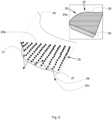
- a completely coded two-dimensional pattern 3 is used by the projector 9, which generates a two-dimensional coding and is thus suitable for the recognition of correspondences in a single image.
- the pattern 3 to be projected or projected onto a flat plane is provided with individual pattern points 8 in 2 shown in more detail using an example.
- a randomly coded pattern 3 (pseudo-random pattern) has proven to be particularly advantageous because it can be used to generate large-area patterns which are still clearly coded in small areas with a few pattern points, and because they are easy to evaluate.
- This pattern 3 is also slightly shifted several times in a row, so that in addition to the two-dimensional coding there is also a temporal coding in which individual pixels of the projected pattern 3 in the image of the cameras 4.1, 4.2, 4.3, 4.4 show different information over time .
- a temporal coding is achieved by the temporally different information.
- the preferred proposed provision of a two-dimensional and a time-based coding combines the advantages of the two-dimensional and the time-based coding without taking over the disadvantages, since it is sufficient for each point or the measurement of each point (pixel) that one of the codes is successfully evaluated can.
- the method is very robust due to the redundancies, and very good accuracy is achieved.
- a random small displacement of the same pattern has proven to be advantageous. This is advantageous because it is very easy and inexpensive to implement.
- a complex projector 9 capable of projecting different images is not required. Instead, a simple projector will suffice 9, in which a single slide is moved at random. "Random” refers to the fact that the movement is not related to the point in time when the picture was taken. One could also use a regular movement that is not synchronized to the image acquisition.
- the displacements also include those that are smaller than a pattern point 8 of the two-dimensional pattern 3, because this allows the accuracy to be further increased.
- the method works even if this condition is not met.
- different patterns 3 could also be projected one after the other.
- four cameras 4.1, 4.2, 4.3, 4.4 are preferably used from different perspectives 6.1, 6.2, 6.3, 6.4, which all look into the same measurement volume, i.e. see and record the same pattern 3 projected by the projector 9 .
- a two-dimensionally coded pattern 3 is projected onto the object surface by means of the projector 9 and the pattern 3 referred to as a scene and projected onto the object surface is recorded with the four cameras 4.1 , 4.2, 4.3, 4.4, which are preferably triggered at the same time, recorded. This creates the two-dimensional coding.
- a time-coded pattern with area-wide different coding is projected multiple times in succession and multiple scenes are recorded in succession with the cameras 4.1, 4.2, 4.3, 4.4, each triggered at the same time.
- the time-coded pattern is generated by multiple spatial displacements of the same area-coded pattern 3 .
- step 53 correspondences in the images recorded by the various cameras 4.1, 4.2, 4.3, 4.4 are found for a pixel in the areal coding in the scene by comparison with neighboring pixels. As a result, the same pixels in the individual images are identified and, if necessary, measured.
- step 54 correspondences are found in the temporal coding for the plurality of scenes in the same image points of the images recorded by the various cameras. As a result, the same pixels are identified in individual images and, if necessary, measured.
- a subsequent method step 55 the found correspondences of the areal coding and the temporal coding are correlated for each pixel and these correlations are used when measuring the object.
- FIG. 4 shows schematically the result of the measurement of a three-dimensional object 20, which is shown schematically in the contour in this figure.
- the object has an upper surface 21 (in the sense of a higher surface) and a lower surface 22 (in the sense of a lower surface) in relation to the object height.
- the upper surface 21 has an edge 23 at its edge where it merges into the lower surface 22.
- a grid 24 is also shown, with which the surface of the object 20 is to be de facto scanned by the measurement.
- a raster element 24a is assigned to the upper surface 21 and a raster element 24b to the lower surface 22 .
- the grid 24 is generated during the survey according to the method of the invention, each of the Grid elements 24a, 24b is described by a three-dimensional coordinate point 25, which was determined by stereoscopy.
- the grid element size may or may not match the pixel of the camera.
- a raster element is usually formed by a number of combined camera pixels. All of the coordinate points 25 are also referred to as a point cloud, which describes the surface of the object 20 as the result of the measurement.
- coordinate points 25a are assigned to the upper surface and coordinate points 8b to the lower surface 25b.
- Coordinate points 25c describe grid elements that lie in the area of edge 23. These are usually afflicted with an error 26, which is based on the fact that the evaluation of the camera pixels in the area of the edge is difficult and the coordinates of the raster elements of the raster 24 can often only be determined with larger errors by means of stereoscopy. There are also raster elements 24c for which no coordinate point was calculated at all, for example because the stereoscopic evaluation of the camera images was incorrect. Such grid elements 24c without a coordinate point are also often found in the area of the edge 23.
- figure 5 theoretically illustrates the systematic procedure when measuring the object 20, shows 4 the cloud of points as a whole of the coordinate points 25, as determined by the method proposed according to the invention.
- the surface of the object 20 can be recognized very well overall by the coordinate points 25a, 25b.
- the reconstructed edge 27, which would be extracted from such a cloud of points 25 is erroneous because the erroneous coordinate points 25c and the resulting from the Grid elements 24c resulting gaps go into the reconstructed edge 25, which is therefore blurred and frayed.
- the invention proposes in the area of edges 23 (to be understood generally as a discontinuous surface area of the object 20), a camera image 28 of at least one of the cameras 4.1, 4.2, 4.3, 4.4, with which the scene is recorded, in addition to the measurement of the Evaluate the object using stereoscopy using two-dimensional image analysis for edge detection. this is in 6 shown schematically.
- FIG. 6 shows the upper part of the point cloud with the upper surface 24a of the object 20 representing coordinate points 25a.
- the reconstructed edge 27 and the associated coordinate points 25a, 25c of the upper surface 25a and on the edge 23 are drawn in.
- the edge 23 of the object 20 was additionally evaluated by means of two-dimensional image analysis, in which edge detection was also carried out according to the invention. This can be done using conventional methods for two-dimensional image analysis, for example using contour recognition. These processes are known in principle to those skilled in the art and do not need to be described further.
- the edge 23 can be extracted with sub-pixel accuracy in the camera image 28 and correspondingly parameterized in the two-dimensional image coordinates.
- the parameterized edge 29 can, as in 6 shown as a line. It covers the course of the edge 23 in the recorded image 28.
- This edge 29, which is parameterized in the two-dimensional image, is transformed into the real coordinates of the scene with the aid of the known camera calibration.
- the two-dimensionally parameterized edge 29 is transformed into the three-dimensional scene.
- the parameterized edge 29 can thus be represented as a three-dimensional edge 30 in the coordinates of the scene.
- the three-dimensional edge 30 can be projected into the point cloud of coordinate points that describes the surface of the measured object 20 .
- This projection can be three-dimensional edge 30 in the point cloud of the coordinate points is in 6 represented by the dashed lines.
- This projection is not a transformation; the three-dimensional coordinates of the three-dimensional edge 30 and the projected edge 31 are the same.
- the projection is only about a joint representation of the coordinate points 25 and the three-dimensional edge 30. This relates to a graphic projection, such as that shown in FIG 6 is shown.
- a projection in the sense of this text is also to be understood as a numerical projection, which is used, for example, for a numerical reconstruction of the surface of the object 20 and in which the three-dimensional edge 30 and the coordinate points 25c on the edge can be taken into account in order to achieve a realistic edge profile overall in the measurement of the surface, e.g. by averaging the coordinates describing the course of the edge, by suppressing identified error coordinates or the like.
- the edge 23 of the object 20 can thus be measured (determined) much more precisely than just from the point cloud of the coordinate points 25 reconstructed by stereometry. It is of particular advantage here that the sub-pixel-precise reconstruction of the course of the edge leads to a more precise and smoother reconstruction than western ones a purely stereometric measurement.
- the measurement of three-dimensional objects 2 is particularly robust as a result of the combination of area and time coding proposed according to the invention and the use of at least three cameras 4.1, 4.2, 4.3, 4.4.
Landscapes
- Engineering & Computer Science (AREA)
- Physics & Mathematics (AREA)
- Computer Vision & Pattern Recognition (AREA)
- General Physics & Mathematics (AREA)
- Theoretical Computer Science (AREA)
- Optics & Photonics (AREA)
- Length Measuring Devices By Optical Means (AREA)
Claims (13)
- Procédé de mesure d'un objet (2) au moyen de la stéréoscopie, dans lequel un motif (3) est projeté sur la surface de l'objet au moyen d'un projecteur (9) et le motif (3) projeté sur la surface de l'objet, appelée scène, est enregistré avec au moins trois caméras calibrées intrinsèquement et extrinsèquement(4.1, 4.2, 4.3, 4.4), dans lequel des correspondances de la scène sont trouvées au moyen d'une unité de calculateur (5) par traitement d'image dans les images enregistrées par les caméras (4.1, 4.2, 4.3, 4.4) et une mesure de l'objet (2) est effectuée au moyen des correspondances trouvées, dans lequel un codage bidimensionnel et temporel est généré lors de la projection du motif par codage spatial et temporel, en ce que• un motif entièrement codé spatialement (3) est projeté et la scène est enregistrée avec les caméras (4.1, 4.2, 4.3, 4.4), et• un motif codé temporellement avec un codage différent à l'échelle de la zone est projeté plusieurs fois de suite et plusieurs scènes sont enregistrées les unes après les autres avec les caméras (4.1, 4.2, 4.3, 4.4) enregistrées simultanément déclenchées,dans lequel• des correspondances de pixels voisins dans les images enregistrées par les différentes caméras (4.1, 4.2, 4.3, 4.4) sont trouvées dans le cadre du codage spatial de la scène,• des correspondances sont trouvées dans le cadre du codage temporel pour les plusieurs scènes dans les mêmes pixels des images enregistrées par les différentes caméras (4.1, 4.2, 4.3, 4.4), et• des correspondances du codage spatial et du codage temporel trouvées pour chacune pixel sont corrélés et ces corrélations sont utilisés lors de la mesure de l'objet (2),caractérisé en ce que la scène est enregistrée avec les au moins trois caméras (4.1, 4.2, 4.3, 4.4) à partir de différentes perspectives (6.1, 6.2, 6.3, 6.4) et chaque sous-système de deux caméras (4.1, 4.2, 4.3, 4.4) est formé à partir des multiples caméras (4.1, 4.2, 4.3, 4.4) et des caméras (4.1 , 4.2, 4.3, 4.4) sont recalibrées en utilisant toujours les valeurs mesurées des autres sous-systèmes pour calibrer un sous-système.
- Procédé selon la revendication 1, caractérisé en ce que le motif codé temporellement est généré par déplacement spatial du même motif codé spatialement (3) .
- Procédé selon la revendication 2, caractérisé en ce que le déplacement spatial du motif (3) et l'enregistrement de la scène par les caméras (4.1, 4.2, 4.3, 4.4) qui se déclenchent simultanément ne sont pas coordonnés l'un avec l'autre.
- Procédé selon la revendication 2 ou 3, caractérisé en ce que la taille du déplacement spatial du motif (3) diffère entre les scènes enregistrées les unes après les autres.
- Procédé selon une quelconque des revendications 2 à 4, caractérisé en ce que la taille d'au moins un des déplacements spatiaux est inférieure à un point du motif (8) du motif plan (3).
- Procédé selon une quelconque des revendications précédentes, caractérisé en ce que le motif codé temporellement est généré par projection déphasée d'une distribution de luminosité.
- Procédé selon une des revendications précédentes, caractérisé en ce que le motif codé temporellement est généré en projetant différents motifs (3) décalés dans le temps.
- Procédé selon une quelconque des revendications précédentes, caractérisé en ce que pour un pixel (8) une corrélation des informations de toutes les caméras (4.1, 4.2, 4.3, 4.4) est effectuée.
- Procédé selon une quelconque des revendications précédentes, caractérisé en ce que la scène est enregistrée avec quatre caméras (4.1, 4.2, 4.3, 4.4) sous des angles différents (6.1, 6.2, 6.3, 6.4).
- Procédé selon une quelconque des revendications précédentes, caractérisé en ce que les images des caméras individuelles (4.1, 4.2, 4.3, 4.4) sont évaluées au moyen d'une analyse d'image bidimensionnelle pour la détection de bord et qu'un bord détecté dans une image est projeté dans un nuage de points tridimensionnel, qui représente un résultat de la mesure tridimensionnelle de l'objet (2).
- Procédé selon la revendication 10, caractérisé en ce que pour l'analyse d'image bidimensionnelle, la scène est en outre enregistrée avec les caméras (4.1, 4.2, 4.3, 4.4) sans projeter de motif.
- Système de mesure d'un objet (2) par stéréoscopie avec un projecteur (9) pour projeter (7) un motif codé (3) sur la surface de l'objet avec des caméras (4.1, 4.2, 4.3, 4.4) pour enregistrer le motif (3) projeté sur la surface de l'objet en tant que scène et avec une unité de calculateur (5), qui est configurée par un programme de traitement d'images pour trouver des correspondances de la scène dans les images enregistrées par les caméras (4.1, 4.2, 4.3, 4.4) et pour effectuer une mesure de l'objet (2)au moyen des correspondances trouvées, dans lequel les caméras (4.1, 4.2, 4.3, 4.4) sont calibrées intrinsèquement et extrinsèquement, caractérisé en ce qu'il est prévu au moins trois caméras (4.1, 42, 4.3, 4.4) , qui sont disposées de telle sorte que la scène soit enregistrée sous au moins trois angles différents (6.1, 6.2, 6.3, 6.4) et que le système soit agencé pour mettre en œuvre le procédé selon une quelconque des revendications 1 à 11.
- Système selon la revendication 12, caractérisé en ce qu'au moins quatre caméras (4.1, 4.2, 4.3, 4.4) sont prévues et agencées de manière à ce que la scène soit enregistrée à partir d'au moins quatre perspectives différentes (6.1, 6.2, 6.3, 6.4).
Applications Claiming Priority (2)
| Application Number | Priority Date | Filing Date | Title |
|---|---|---|---|
| DE102018108874.4A DE102018108874A1 (de) | 2018-04-13 | 2018-04-13 | Verfahren und System zur Vermessung eines Objekts mittels Stereoskopie |
| PCT/EP2019/059521 WO2019197656A1 (fr) | 2018-04-13 | 2019-04-12 | Procédé et système de mesure d'un objet par stéréoscopie |
Publications (2)
| Publication Number | Publication Date |
|---|---|
| EP3775767A1 EP3775767A1 (fr) | 2021-02-17 |
| EP3775767B1 true EP3775767B1 (fr) | 2023-07-05 |
Family
ID=66251750
Family Applications (1)
| Application Number | Title | Priority Date | Filing Date |
|---|---|---|---|
| EP19719201.6A Active EP3775767B1 (fr) | 2018-04-13 | 2019-04-12 | Procédé et système de mesure d'un objet par stéréoscopie |
Country Status (5)
| Country | Link |
|---|---|
| US (1) | US11640673B2 (fr) |
| EP (1) | EP3775767B1 (fr) |
| CN (1) | CN111971525B (fr) |
| DE (1) | DE102018108874A1 (fr) |
| WO (1) | WO2019197656A1 (fr) |
Families Citing this family (8)
| Publication number | Priority date | Publication date | Assignee | Title |
|---|---|---|---|---|
| IL280324B2 (en) | 2018-07-24 | 2025-07-01 | Glasstech Inc | System and method for measuring surface area in glass sheets with contours |
| FR3098929B1 (fr) * | 2019-07-16 | 2021-06-18 | Yellowscan | Procédé de détermination de paramètres d'étalonnage extrinseques d'un système de mesure |
| WO2021051126A1 (fr) * | 2019-09-11 | 2021-03-18 | The Johns Hopkins University | Dispositif portable de mappage de projection et système de projection |
| EP3822578B1 (fr) * | 2019-11-15 | 2024-07-24 | Hexagon Technology Center GmbH | Scanner 3d adaptatif à plage de mesure variable |
| DE102022112625A1 (de) | 2022-05-19 | 2023-11-23 | Isra Vision Gmbh | Verfahren und Vorrichtung zur Ausrichtung von Kameras |
| US11867630B1 (en) | 2022-08-09 | 2024-01-09 | Glasstech, Inc. | Fixture and method for optical alignment in a system for measuring a surface in contoured glass sheets |
| DE102023113821A1 (de) * | 2023-05-25 | 2024-11-28 | ibea Ingenieurbüro für Elektronik und Automatisation GmbH | Inspektionsvorrichtung für Baustoffe und Verfahren zur Inspektion von Baustoffen |
| EP4731961A1 (fr) * | 2023-06-21 | 2026-04-29 | Creaform Inc. | Procédé d'étalonnage d'au moins une caméra d'un scanner 3d et système de numérisation 3d mettant en oeuvre ledit procédé |
Citations (1)
| Publication number | Priority date | Publication date | Assignee | Title |
|---|---|---|---|---|
| US20170034499A1 (en) * | 2014-04-03 | 2017-02-02 | Heptagon Micro Optics Pte. Ltd. | Structured-stereo imaging assembly including separate imagers for different wavelengths |
Family Cites Families (19)
| Publication number | Priority date | Publication date | Assignee | Title |
|---|---|---|---|---|
| DE19502459A1 (de) * | 1995-01-28 | 1996-08-01 | Wolf Henning | Verfahren zur dreidimensionalen optischen Vermessung der Oberfläche von Objekten |
| US7103212B2 (en) * | 2002-11-22 | 2006-09-05 | Strider Labs, Inc. | Acquisition of three-dimensional images by an active stereo technique using locally unique patterns |
| CN100449258C (zh) * | 2006-04-27 | 2009-01-07 | 浙江工业大学 | 基于二维彩色光编码的实时三维视觉系统 |
| CN101667303B (zh) * | 2009-09-29 | 2013-01-16 | 浙江工业大学 | 一种基于编码结构光的三维重建方法 |
| DE102011008655A1 (de) * | 2011-01-14 | 2012-07-19 | Inb Vision Ag | Vorrichtung und Verfahren zur dreidimensionalen optischen Vermessung von Oberflächen |
| US8723789B1 (en) * | 2011-02-11 | 2014-05-13 | Imimtek, Inc. | Two-dimensional method and system enabling three-dimensional user interaction with a device |
| EP2527784A1 (fr) * | 2011-05-19 | 2012-11-28 | Hexagon Technology Center GmbH | Procédé de mesure optique et système de mesure destiné à la détermination de coordonnées 3D sur la surface d'un objet à mesurer |
| DE102011121696A1 (de) * | 2011-12-16 | 2013-06-20 | Friedrich-Schiller-Universität Jena | Verfahren zur 3D-Messung von tiefenlimitierten Objekten |
| DE102011121969A1 (de) | 2011-12-21 | 2013-06-27 | Deutsche Telekom Ag | Verfahren zum Betreiben eines elektronischen Endgeräts |
| US9185392B2 (en) * | 2012-11-12 | 2015-11-10 | Spatial Integrated Systems, Inc. | System and method for 3-D object rendering of a moving object using structured light patterns and moving window imagery |
| US20140198185A1 (en) * | 2013-01-17 | 2014-07-17 | Cyberoptics Corporation | Multi-camera sensor for three-dimensional imaging of a circuit board |
| US9256944B2 (en) * | 2014-05-19 | 2016-02-09 | Rockwell Automation Technologies, Inc. | Integration of optical area monitoring with industrial machine control |
| US10582186B1 (en) * | 2014-06-11 | 2020-03-03 | Amazon Technologies, Inc. | Approaches for identifying misaligned cameras |
| US9325973B1 (en) | 2014-07-08 | 2016-04-26 | Aquifi, Inc. | Dynamically reconfigurable optical pattern generator module useable with a system to rapidly reconstruct three-dimensional data |
| WO2016106196A1 (fr) * | 2014-12-22 | 2016-06-30 | Cyberoptics Corporation | Actualisation de l'étalonnage d'un système de mesure tridimensionnelle |
| US20170094251A1 (en) * | 2015-09-30 | 2017-03-30 | Faro Technologies, Inc. | Three-dimensional imager that includes a dichroic camera |
| DE102016002398B4 (de) | 2016-02-26 | 2019-04-25 | Gerd Häusler | Optischer 3D-Sensor zur schnellen und dichten Formerfassung |
| US10602126B2 (en) * | 2016-06-10 | 2020-03-24 | Lucid VR, Inc. | Digital camera device for 3D imaging |
| US20170374331A1 (en) * | 2016-06-27 | 2017-12-28 | Intel Corporation | Auto keystone correction and auto focus adjustment |
-
2018
- 2018-04-13 DE DE102018108874.4A patent/DE102018108874A1/de not_active Ceased
-
2019
- 2019-04-12 WO PCT/EP2019/059521 patent/WO2019197656A1/fr not_active Ceased
- 2019-04-12 CN CN201980025388.1A patent/CN111971525B/zh active Active
- 2019-04-12 EP EP19719201.6A patent/EP3775767B1/fr active Active
- 2019-04-12 US US17/045,702 patent/US11640673B2/en active Active
Patent Citations (1)
| Publication number | Priority date | Publication date | Assignee | Title |
|---|---|---|---|---|
| US20170034499A1 (en) * | 2014-04-03 | 2017-02-02 | Heptagon Micro Optics Pte. Ltd. | Structured-stereo imaging assembly including separate imagers for different wavelengths |
Also Published As
| Publication number | Publication date |
|---|---|
| CN111971525B (zh) | 2023-02-28 |
| WO2019197656A1 (fr) | 2019-10-17 |
| DE102018108874A1 (de) | 2019-10-17 |
| CN111971525A (zh) | 2020-11-20 |
| US11640673B2 (en) | 2023-05-02 |
| EP3775767A1 (fr) | 2021-02-17 |
| US20210166412A1 (en) | 2021-06-03 |
Similar Documents
| Publication | Publication Date | Title |
|---|---|---|
| EP3775767B1 (fr) | Procédé et système de mesure d'un objet par stéréoscopie | |
| DE102012108567B4 (de) | Verfahren zum Erlangen von Tiefeninformationen unter Verwendung eines Lichtmusters | |
| DE102007054906B4 (de) | Verfahren zur optischen Vermessung der dreidimensionalen Geometrie von Objekten | |
| DE10020893B4 (de) | Verfahren zur optischen Formerfassung von Gegenständen | |
| EP1971820B1 (fr) | Etablissement d'une image de distance | |
| EP0897524B1 (fr) | Dispositif pour mesurer sans contact une surface d'objet en trois dimensions | |
| DE102017010683B4 (de) | Verfahren zur automatischen Wiederherstellung eines eingemessenen Zustands eines Projektionssystems | |
| DE19623172C1 (de) | Verfahren zur dreidimensionalen optischen Vermessung von Objektoberflächen | |
| EP2002203A2 (fr) | Procede et systeme de mesure de la forme d`une surface reflechissante | |
| WO2017220598A1 (fr) | Procédé de mesure tridimensionnelle d'objets mobiles suivant un déplacement connu | |
| EP2400261A1 (fr) | Procédé de mesure optique et système de mesure destiné à la détermination de coordonnées 3D sur la surface d'un objet de mesure | |
| DE102018004592A1 (de) | Messapparat für dreidimensionale Geometrie und Messverfahren für dreidimensionale Geometrie | |
| DE102006055758B4 (de) | Verfahren zur Kalibrierung von Kameras und Projektoren | |
| DE10149750A1 (de) | Handgeführter 3D-Scanner | |
| DE602004011093T2 (de) | Einrichtung zum scannen dreidimensionaler objekte | |
| EP2275989A1 (fr) | Caméra 3D stéréoscopique | |
| EP1485670A2 (fr) | Procede et dispositif pour determiner les coordonnees absolues d'un objet | |
| EP3907466A1 (fr) | Capteur 3d et méthode d'acquisition de données d'image tridimensionnelles d'un objet | |
| WO2016146105A1 (fr) | Procédé et dispositif d'étalonnage d'une caméra | |
| DE102019208474A1 (de) | Verfahren und System zum optischen Vermessen eines Objekts mit spiegelnder und/oder teilspiegelnder Oberfläche sowie entsprechende Messanordnung | |
| EP3274652A1 (fr) | Procédé de projection en photogrammes, dispositif de projection en photogrammes et produit-programme informatique | |
| DE102006059416B4 (de) | Vorrichtung und Verfahren zur Steigerung der Messgenauigkeit digitaler 3D-Geometriemesssysteme | |
| EP2887010B1 (fr) | Procédé et dispositif de mesure optique en trois dimensions d'objets avec un procédé de mesure topométrique ainsi que programme informatique correspondant | |
| DE102019006314A1 (de) | Dreidimensionale-Geometrie-Messvorrichtung und Dreidimensionale-Geometrie-Messverfahren | |
| DE102018115673A1 (de) | Verfahren und Vorrichtungen zur Musterprojektion |
Legal Events
| Date | Code | Title | Description |
|---|---|---|---|
| STAA | Information on the status of an ep patent application or granted ep patent |
Free format text: STATUS: UNKNOWN |
|
| STAA | Information on the status of an ep patent application or granted ep patent |
Free format text: STATUS: THE INTERNATIONAL PUBLICATION HAS BEEN MADE |
|
| PUAI | Public reference made under article 153(3) epc to a published international application that has entered the european phase |
Free format text: ORIGINAL CODE: 0009012 |
|
| STAA | Information on the status of an ep patent application or granted ep patent |
Free format text: STATUS: REQUEST FOR EXAMINATION WAS MADE |
|
| 17P | Request for examination filed |
Effective date: 20201005 |
|
| AK | Designated contracting states |
Kind code of ref document: A1 Designated state(s): AL AT BE BG CH CY CZ DE DK EE ES FI FR GB GR HR HU IE IS IT LI LT LU LV MC MK MT NL NO PL PT RO RS SE SI SK SM TR |
|
| AX | Request for extension of the european patent |
Extension state: BA ME |
|
| DAV | Request for validation of the european patent (deleted) | ||
| DAX | Request for extension of the european patent (deleted) | ||
| GRAP | Despatch of communication of intention to grant a patent |
Free format text: ORIGINAL CODE: EPIDOSNIGR1 |
|
| STAA | Information on the status of an ep patent application or granted ep patent |
Free format text: STATUS: GRANT OF PATENT IS INTENDED |
|
| INTG | Intention to grant announced |
Effective date: 20230222 |
|
| GRAS | Grant fee paid |
Free format text: ORIGINAL CODE: EPIDOSNIGR3 |
|
| GRAA | (expected) grant |
Free format text: ORIGINAL CODE: 0009210 |
|
| STAA | Information on the status of an ep patent application or granted ep patent |
Free format text: STATUS: THE PATENT HAS BEEN GRANTED |
|
| AK | Designated contracting states |
Kind code of ref document: B1 Designated state(s): AL AT BE BG CH CY CZ DE DK EE ES FI FR GB GR HR HU IE IS IT LI LT LU LV MC MK MT NL NO PL PT RO RS SE SI SK SM TR |
|
| REG | Reference to a national code |
Ref country code: CH Ref legal event code: EP |
|
| REG | Reference to a national code |
Ref country code: AT Ref legal event code: REF Ref document number: 1585205 Country of ref document: AT Kind code of ref document: T Effective date: 20230715 |
|
| REG | Reference to a national code |
Ref country code: DE Ref legal event code: R096 Ref document number: 502019008402 Country of ref document: DE |
|
| REG | Reference to a national code |
Ref country code: IE Ref legal event code: FG4D Free format text: LANGUAGE OF EP DOCUMENT: GERMAN |
|
| REG | Reference to a national code |
Ref country code: DE Ref legal event code: R081 Ref document number: 502019008402 Country of ref document: DE Owner name: ISRA VISION GMBH, DE Free format text: FORMER OWNER: ISRA VISION AG, 64297 DARMSTADT, DE Ref country code: DE Ref legal event code: R081 Ref document number: 502019008402 Country of ref document: DE Owner name: ISRA VISION GMBH, DE Free format text: FORMER OWNER: UNGUELTIGER ANMELDER, 80331 MUENCHEN, DE |
|
| REG | Reference to a national code |
Ref country code: LT Ref legal event code: MG9D |
|
| REG | Reference to a national code |
Ref country code: NL Ref legal event code: MP Effective date: 20230705 |
|
| PG25 | Lapsed in a contracting state [announced via postgrant information from national office to epo] |
Ref country code: NL Free format text: LAPSE BECAUSE OF FAILURE TO SUBMIT A TRANSLATION OF THE DESCRIPTION OR TO PAY THE FEE WITHIN THE PRESCRIBED TIME-LIMIT Effective date: 20230705 |
|
| PG25 | Lapsed in a contracting state [announced via postgrant information from national office to epo] |
Ref country code: GR Free format text: LAPSE BECAUSE OF FAILURE TO SUBMIT A TRANSLATION OF THE DESCRIPTION OR TO PAY THE FEE WITHIN THE PRESCRIBED TIME-LIMIT Effective date: 20231006 |
|
| PG25 | Lapsed in a contracting state [announced via postgrant information from national office to epo] |
Ref country code: ES Free format text: LAPSE BECAUSE OF FAILURE TO SUBMIT A TRANSLATION OF THE DESCRIPTION OR TO PAY THE FEE WITHIN THE PRESCRIBED TIME-LIMIT Effective date: 20230705 |
|
| PG25 | Lapsed in a contracting state [announced via postgrant information from national office to epo] |
Ref country code: IS Free format text: LAPSE BECAUSE OF FAILURE TO SUBMIT A TRANSLATION OF THE DESCRIPTION OR TO PAY THE FEE WITHIN THE PRESCRIBED TIME-LIMIT Effective date: 20231105 |
|
| PG25 | Lapsed in a contracting state [announced via postgrant information from national office to epo] |
Ref country code: SE Free format text: LAPSE BECAUSE OF FAILURE TO SUBMIT A TRANSLATION OF THE DESCRIPTION OR TO PAY THE FEE WITHIN THE PRESCRIBED TIME-LIMIT Effective date: 20230705 Ref country code: RS Free format text: LAPSE BECAUSE OF FAILURE TO SUBMIT A TRANSLATION OF THE DESCRIPTION OR TO PAY THE FEE WITHIN THE PRESCRIBED TIME-LIMIT Effective date: 20230705 Ref country code: PT Free format text: LAPSE BECAUSE OF FAILURE TO SUBMIT A TRANSLATION OF THE DESCRIPTION OR TO PAY THE FEE WITHIN THE PRESCRIBED TIME-LIMIT Effective date: 20231106 Ref country code: NO Free format text: LAPSE BECAUSE OF FAILURE TO SUBMIT A TRANSLATION OF THE DESCRIPTION OR TO PAY THE FEE WITHIN THE PRESCRIBED TIME-LIMIT Effective date: 20231005 Ref country code: LV Free format text: LAPSE BECAUSE OF FAILURE TO SUBMIT A TRANSLATION OF THE DESCRIPTION OR TO PAY THE FEE WITHIN THE PRESCRIBED TIME-LIMIT Effective date: 20230705 Ref country code: LT Free format text: LAPSE BECAUSE OF FAILURE TO SUBMIT A TRANSLATION OF THE DESCRIPTION OR TO PAY THE FEE WITHIN THE PRESCRIBED TIME-LIMIT Effective date: 20230705 Ref country code: IS Free format text: LAPSE BECAUSE OF FAILURE TO SUBMIT A TRANSLATION OF THE DESCRIPTION OR TO PAY THE FEE WITHIN THE PRESCRIBED TIME-LIMIT Effective date: 20231105 Ref country code: HR Free format text: LAPSE BECAUSE OF FAILURE TO SUBMIT A TRANSLATION OF THE DESCRIPTION OR TO PAY THE FEE WITHIN THE PRESCRIBED TIME-LIMIT Effective date: 20230705 Ref country code: GR Free format text: LAPSE BECAUSE OF FAILURE TO SUBMIT A TRANSLATION OF THE DESCRIPTION OR TO PAY THE FEE WITHIN THE PRESCRIBED TIME-LIMIT Effective date: 20231006 Ref country code: FI Free format text: LAPSE BECAUSE OF FAILURE TO SUBMIT A TRANSLATION OF THE DESCRIPTION OR TO PAY THE FEE WITHIN THE PRESCRIBED TIME-LIMIT Effective date: 20230705 Ref country code: ES Free format text: LAPSE BECAUSE OF FAILURE TO SUBMIT A TRANSLATION OF THE DESCRIPTION OR TO PAY THE FEE WITHIN THE PRESCRIBED TIME-LIMIT Effective date: 20230705 |
|
| PG25 | Lapsed in a contracting state [announced via postgrant information from national office to epo] |
Ref country code: PL Free format text: LAPSE BECAUSE OF FAILURE TO SUBMIT A TRANSLATION OF THE DESCRIPTION OR TO PAY THE FEE WITHIN THE PRESCRIBED TIME-LIMIT Effective date: 20230705 |
|
| REG | Reference to a national code |
Ref country code: DE Ref legal event code: R097 Ref document number: 502019008402 Country of ref document: DE |
|
| PG25 | Lapsed in a contracting state [announced via postgrant information from national office to epo] |
Ref country code: SM Free format text: LAPSE BECAUSE OF FAILURE TO SUBMIT A TRANSLATION OF THE DESCRIPTION OR TO PAY THE FEE WITHIN THE PRESCRIBED TIME-LIMIT Effective date: 20230705 Ref country code: RO Free format text: LAPSE BECAUSE OF FAILURE TO SUBMIT A TRANSLATION OF THE DESCRIPTION OR TO PAY THE FEE WITHIN THE PRESCRIBED TIME-LIMIT Effective date: 20230705 Ref country code: EE Free format text: LAPSE BECAUSE OF FAILURE TO SUBMIT A TRANSLATION OF THE DESCRIPTION OR TO PAY THE FEE WITHIN THE PRESCRIBED TIME-LIMIT Effective date: 20230705 Ref country code: DK Free format text: LAPSE BECAUSE OF FAILURE TO SUBMIT A TRANSLATION OF THE DESCRIPTION OR TO PAY THE FEE WITHIN THE PRESCRIBED TIME-LIMIT Effective date: 20230705 Ref country code: CZ Free format text: LAPSE BECAUSE OF FAILURE TO SUBMIT A TRANSLATION OF THE DESCRIPTION OR TO PAY THE FEE WITHIN THE PRESCRIBED TIME-LIMIT Effective date: 20230705 Ref country code: SK Free format text: LAPSE BECAUSE OF FAILURE TO SUBMIT A TRANSLATION OF THE DESCRIPTION OR TO PAY THE FEE WITHIN THE PRESCRIBED TIME-LIMIT Effective date: 20230705 |
|
| PLBE | No opposition filed within time limit |
Free format text: ORIGINAL CODE: 0009261 |
|
| STAA | Information on the status of an ep patent application or granted ep patent |
Free format text: STATUS: NO OPPOSITION FILED WITHIN TIME LIMIT |
|
| PG25 | Lapsed in a contracting state [announced via postgrant information from national office to epo] |
Ref country code: IT Free format text: LAPSE BECAUSE OF FAILURE TO SUBMIT A TRANSLATION OF THE DESCRIPTION OR TO PAY THE FEE WITHIN THE PRESCRIBED TIME-LIMIT Effective date: 20230705 |
|
| 26N | No opposition filed |
Effective date: 20240408 |
|
| PG25 | Lapsed in a contracting state [announced via postgrant information from national office to epo] |
Ref country code: SI Free format text: LAPSE BECAUSE OF FAILURE TO SUBMIT A TRANSLATION OF THE DESCRIPTION OR TO PAY THE FEE WITHIN THE PRESCRIBED TIME-LIMIT Effective date: 20230705 |
|
| PG25 | Lapsed in a contracting state [announced via postgrant information from national office to epo] |
Ref country code: BG Free format text: LAPSE BECAUSE OF FAILURE TO SUBMIT A TRANSLATION OF THE DESCRIPTION OR TO PAY THE FEE WITHIN THE PRESCRIBED TIME-LIMIT Effective date: 20230705 |
|
| P01 | Opt-out of the competence of the unified patent court (upc) registered |
Free format text: CASE NUMBER: APP_56527/2024 Effective date: 20241016 |
|
| PG25 | Lapsed in a contracting state [announced via postgrant information from national office to epo] |
Ref country code: MC Free format text: LAPSE BECAUSE OF FAILURE TO SUBMIT A TRANSLATION OF THE DESCRIPTION OR TO PAY THE FEE WITHIN THE PRESCRIBED TIME-LIMIT Effective date: 20230705 |
|
| PG25 | Lapsed in a contracting state [announced via postgrant information from national office to epo] |
Ref country code: MC Free format text: LAPSE BECAUSE OF FAILURE TO SUBMIT A TRANSLATION OF THE DESCRIPTION OR TO PAY THE FEE WITHIN THE PRESCRIBED TIME-LIMIT Effective date: 20230705 Ref country code: BG Free format text: LAPSE BECAUSE OF FAILURE TO SUBMIT A TRANSLATION OF THE DESCRIPTION OR TO PAY THE FEE WITHIN THE PRESCRIBED TIME-LIMIT Effective date: 20230705 |
|
| REG | Reference to a national code |
Ref country code: CH Ref legal event code: PL |
|
| PG25 | Lapsed in a contracting state [announced via postgrant information from national office to epo] |
Ref country code: LU Free format text: LAPSE BECAUSE OF NON-PAYMENT OF DUE FEES Effective date: 20240412 |
|
| REG | Reference to a national code |
Ref country code: BE Ref legal event code: MM Effective date: 20240430 |
|
| PG25 | Lapsed in a contracting state [announced via postgrant information from national office to epo] |
Ref country code: LU Free format text: LAPSE BECAUSE OF NON-PAYMENT OF DUE FEES Effective date: 20240412 |
|
| PG25 | Lapsed in a contracting state [announced via postgrant information from national office to epo] |
Ref country code: BE Free format text: LAPSE BECAUSE OF NON-PAYMENT OF DUE FEES Effective date: 20240430 |
|
| PG25 | Lapsed in a contracting state [announced via postgrant information from national office to epo] |
Ref country code: BE Free format text: LAPSE BECAUSE OF NON-PAYMENT OF DUE FEES Effective date: 20240430 Ref country code: CH Free format text: LAPSE BECAUSE OF NON-PAYMENT OF DUE FEES Effective date: 20240430 |
|
| PG25 | Lapsed in a contracting state [announced via postgrant information from national office to epo] |
Ref country code: IE Free format text: LAPSE BECAUSE OF NON-PAYMENT OF DUE FEES Effective date: 20240412 |
|
| REG | Reference to a national code |
Ref country code: AT Ref legal event code: MM01 Ref document number: 1585205 Country of ref document: AT Kind code of ref document: T Effective date: 20240412 |
|
| PGFP | Annual fee paid to national office [announced via postgrant information from national office to epo] |
Ref country code: DE Payment date: 20250429 Year of fee payment: 7 |
|
| PGFP | Annual fee paid to national office [announced via postgrant information from national office to epo] |
Ref country code: GB Payment date: 20250428 Year of fee payment: 7 |
|
| PGFP | Annual fee paid to national office [announced via postgrant information from national office to epo] |
Ref country code: FR Payment date: 20250425 Year of fee payment: 7 |
|
| PG25 | Lapsed in a contracting state [announced via postgrant information from national office to epo] |
Ref country code: AT Free format text: LAPSE BECAUSE OF NON-PAYMENT OF DUE FEES Effective date: 20240412 |
|
| PG25 | Lapsed in a contracting state [announced via postgrant information from national office to epo] |
Ref country code: CY Free format text: LAPSE BECAUSE OF FAILURE TO SUBMIT A TRANSLATION OF THE DESCRIPTION OR TO PAY THE FEE WITHIN THE PRESCRIBED TIME-LIMIT; INVALID AB INITIO Effective date: 20190412 |
|
| PG25 | Lapsed in a contracting state [announced via postgrant information from national office to epo] |
Ref country code: HU Free format text: LAPSE BECAUSE OF FAILURE TO SUBMIT A TRANSLATION OF THE DESCRIPTION OR TO PAY THE FEE WITHIN THE PRESCRIBED TIME-LIMIT; INVALID AB INITIO Effective date: 20190412 |