EP3775942B1 - Module intermédiaire, module récepteur, système de surveillance et procédé de surveillance - Google Patents
Module intermédiaire, module récepteur, système de surveillance et procédé de surveillance Download PDFInfo
- Publication number
- EP3775942B1 EP3775942B1 EP19717818.9A EP19717818A EP3775942B1 EP 3775942 B1 EP3775942 B1 EP 3775942B1 EP 19717818 A EP19717818 A EP 19717818A EP 3775942 B1 EP3775942 B1 EP 3775942B1
- Authority
- EP
- European Patent Office
- Prior art keywords
- power grid
- intermediate module
- module
- receiver
- operating data
- Prior art date
- Legal status (The legal status is an assumption and is not a legal conclusion. Google has not performed a legal analysis and makes no representation as to the accuracy of the status listed.)
- Active
Links
Images


Classifications
-
- G—PHYSICS
- G01—MEASURING; TESTING
- G01R—MEASURING ELECTRIC VARIABLES; MEASURING MAGNETIC VARIABLES
- G01R21/00—Arrangements for measuring electric power or power factor
- G01R21/133—Arrangements for measuring electric power or power factor by using digital technique
-
- G—PHYSICS
- G01—MEASURING; TESTING
- G01R—MEASURING ELECTRIC VARIABLES; MEASURING MAGNETIC VARIABLES
- G01R22/00—Arrangements for measuring time integral of electric power or current, e.g. electricity meters
- G01R22/06—Arrangements for measuring time integral of electric power or current, e.g. electricity meters by electronic methods
- G01R22/061—Details of electronic electricity meters
- G01R22/063—Details of electronic electricity meters related to remote communication
-
- H—ELECTRICITY
- H02—GENERATION; CONVERSION OR DISTRIBUTION OF ELECTRIC POWER
- H02J—ELECTRIC POWER NETWORKS; CIRCUIT ARRANGEMENTS OR SYSTEMS FOR SUPPLYING OR DISTRIBUTING ELECTRIC POWER; SYSTEMS FOR STORING ELECTRIC ENERGY
- H02J13/00—Circuit arrangements for providing remote monitoring or remote control of equipment in a power distribution network
- H02J13/13—Circuit arrangements for providing remote monitoring or remote control of equipment in a power distribution network characterised by the transmission of data to equipment in the power network
- H02J13/1311—Circuit arrangements for providing remote monitoring or remote control of equipment in a power distribution network characterised by the transmission of data to equipment in the power network using the power network as support for the transmission
-
- G—PHYSICS
- G01—MEASURING; TESTING
- G01R—MEASURING ELECTRIC VARIABLES; MEASURING MAGNETIC VARIABLES
- G01R19/00—Arrangements for measuring currents or voltages or for indicating presence or sign thereof
- G01R19/25—Arrangements for measuring currents or voltages or for indicating presence or sign thereof using digital measurement techniques
- G01R19/2513—Arrangements for monitoring electric power systems, e.g. power lines or loads; Logging
-
- Y—GENERAL TAGGING OF NEW TECHNOLOGICAL DEVELOPMENTS; GENERAL TAGGING OF CROSS-SECTIONAL TECHNOLOGIES SPANNING OVER SEVERAL SECTIONS OF THE IPC; TECHNICAL SUBJECTS COVERED BY FORMER USPC CROSS-REFERENCE ART COLLECTIONS [XRACs] AND DIGESTS
- Y02—TECHNOLOGIES OR APPLICATIONS FOR MITIGATION OR ADAPTATION AGAINST CLIMATE CHANGE
- Y02E—REDUCTION OF GREENHOUSE GAS [GHG] EMISSIONS, RELATED TO ENERGY GENERATION, TRANSMISSION OR DISTRIBUTION
- Y02E60/00—Enabling technologies; Technologies with a potential or indirect contribution to GHG emissions mitigation
-
- Y—GENERAL TAGGING OF NEW TECHNOLOGICAL DEVELOPMENTS; GENERAL TAGGING OF CROSS-SECTIONAL TECHNOLOGIES SPANNING OVER SEVERAL SECTIONS OF THE IPC; TECHNICAL SUBJECTS COVERED BY FORMER USPC CROSS-REFERENCE ART COLLECTIONS [XRACs] AND DIGESTS
- Y04—INFORMATION OR COMMUNICATION TECHNOLOGIES HAVING AN IMPACT ON OTHER TECHNOLOGY AREAS
- Y04S—SYSTEMS INTEGRATING TECHNOLOGIES RELATED TO POWER NETWORK OPERATION, COMMUNICATION OR INFORMATION TECHNOLOGIES FOR IMPROVING THE ELECTRICAL POWER GENERATION, TRANSMISSION, DISTRIBUTION, MANAGEMENT OR USAGE, i.e. SMART GRIDS
- Y04S40/00—Systems for electrical power generation, transmission, distribution or end-user application management characterised by the use of communication or information technologies, or communication or information technology specific aspects supporting them
- Y04S40/12—Systems for electrical power generation, transmission, distribution or end-user application management characterised by the use of communication or information technologies, or communication or information technology specific aspects supporting them characterised by data transport means between the monitoring, controlling or managing units and monitored, controlled or operated electrical equipment
- Y04S40/121—Systems for electrical power generation, transmission, distribution or end-user application management characterised by the use of communication or information technologies, or communication or information technology specific aspects supporting them characterised by data transport means between the monitoring, controlling or managing units and monitored, controlled or operated electrical equipment using the power network as support for the transmission
Definitions
- the invention relates to an intermediate module for switching between a power grid and an electrical consumer in connection with a receiver module for receiving information about operating data of a consumer from a power grid.
- a monitoring system with an intermediate module and a receiver module falls within the scope of the invention.
- the invention relates to the use of a monitoring system for monitoring an electrical consumer and a method for monitoring a manufacturing machine in a manufacturing plant.
- a monitoring system according to claim 1 a use of a monitoring system according to claim 14 and a method for monitoring a manufacturing machine in a manufacturing plant according to claim 15.
- an intermediate module for interconnection between a power grid and an electrical consumer, with an input power connection for connecting the intermediate module to the power grid, and with an output power connection for connecting the consumer to the intermediate module.
- the intermediate module is set up to determine operating data of the consumer and to transmit information about the determined operating data to the power grid via the input power connection.
- the input power connection has three phase conductor input contacts for contacting one phase conductor of the power grid.
- the intermediate module is thus set up to connect a consumer to a three-phase power grid.
- the intermediate module according to the invention is therefore also suitable for use in production machines that are operated with high-voltage current.
- the intermediate module can thus be connected in a simple manner between an electrical load, in particular a production machine, and a three-phase power supply system, in particular a high-voltage power supply system.
- the intermediate module then enables the operating states of the consumer to be monitored by determining its operating data and transmitting information about this to the power grid.
- a line conductor (also known as "phase") is a conductor that is under voltage relative to a neutral conductor in normal service and may contribute to the transmission or distribution of electrical energy, but is not a neutral (middle) conductor. In the case of single-phase connections with a nominal voltage of 230 V, it occurs only once and often bears the designation "L".
- a three-phase power grid has three outer conductors, which are usually designated L1, L2 and L3. In the low-voltage network to which consumers are connected, the effective value of the voltage from external conductors is generally 230 V against the neutral conductor and any protective conductor that may be present and 400 V between each two external conductors with a phase difference of 120° between the AC voltages of the three external conductors.
- the power grid in particular the low-voltage grid, typically has a frequency between 50 Hz and 60 Hz.
- the neutral conductor usually has no voltage with respect to the protective conductor and earth, so that all phase conductors have a voltage of 230 V with respect to earth.
- this is referred to as a high-voltage connection.
- the intermediate module is set up to measure and/or calculate the operating data itself.
- the intermediate module is typically set up to determine the operating data by monitoring the line-to-line input contacts, in particular by measuring current strengths through the line-to-line input contacts and/or voltages between the line-to-line input contacts.
- the information about the operating data can be the numerical values of the operating data, i.e. the operating data itself, so to speak, and/or parameters derived from the operating data determined by the intermediate module.
- the consumer can be a manufacturing machine, in particular a manufacturing machine that is connected to a data infrastructure of a manufacturing company in a little or not at all digitized.
- the production machine can be used at a manual workstation and can be a welding device, for example.
- a manual workstation is a production or manufacturing facility with a low degree of automation and a high proportion of manual work.
- a manual workstation includes a workbench/work surface and usually several tools, which are often operated free-hand by an operator following instructions become.
- the low degree of automation can lead to disruptions and additional work in the process flow, since in addition to the actual production or processing of a workpiece, there are other secondary activities such as the manual creation of work instructions, the printing and appropriation of explanations, instructions and drawings.
- the intermediate module according to the invention can be retrofitted here in a simple manner and then supplies the desired data for production at the manual workstation.
- a manufacturing machine can be a sheet metal or metalworking machine.
- metal and/or sheet metal processing companies often have a medium degree of digitalization. This means that there are many highly digitally networked machines such as CNC metalworking machines, flatbed cutting, bending or punching machines of the newer generation, as well as little to no networked manufacturing machines (such as simple electric saws, drills, riveting tools, milling machines). .
- the older machines often have a very long service life and durability as well as reliability and are reluctant to be exchanged for a new fully automatic machine by plant managers.
- the intermediate module according to the invention enables the integration of the older, proven machines in a digital monitoring and control system of the production plant.
- intermediate modules according to the invention are used for the first time—in contrast to the conventional first use of digitalization solutions—there is no risk of the production machines stopping.
- the intermediate module is simply connected between the production machine and the power grid and conducts the power through. If the digital monitoring system does not work, this has no effect on the operational readiness of the production machine, as it can initially continue to be operated as before - i.e. non-digitalized.
- the input power connection also has a neutral conductor input contact for contacting a neutral conductor of the power grid and/or a protective conductor input contact for contacting a protective conductor of the power grid.
- a neutral conductor input contact for contacting a neutral conductor of the power grid
- a protective conductor input contact for contacting a protective conductor of the power grid.
- the intermediate module is set up to transmit the information about the operating data via exactly one of the outer conductor input contacts. This simplifies the structure of the intermediate module.
- An alternative, advantageous embodiment provides that the intermediate module is set up to transmit the information about the operating data via at least two, preferably via all, external conductor input contacts.
- This alternative offers redundancy and increases the robustness of the information transmission.
- a receiving station can receive the operational data information on any one of the multiple line conductors of the power grid. In the case of transmission via all phase conductor input contacts, the receiving station can in particular also be connected to a single-phase socket of the same power supply, regardless of which of the three phase conductors ends in this socket.
- the input power connection is designed as an intermodule plug for plugging into a socket, in particular the input contacts of the input power connection are each designed as a plug pin.
- the intermediate module can be easily replaced or used on another consumer. This embodiment is particularly suitable for mobile production machines that are to be connected to the power grid at different locations. Protection against interference (damping reactors, ferrites, overvoltage limiters, etc.) can also be integrated into the intermediate module.
- the input power connection can be individually wired to the conductors of the power supply system, for example if the intermediate module is to be mounted in a control cabinet or a media column, for example by means of top-hat rail mounting.
- the output power connection particularly preferably has an assigned output contact for each of the input contacts of the input power connection. This simplifies the connection of the consumer to the intermediate module.
- each of the output contacts is electrically conductively connected to the associated input contact.
- the output power connector includes three line-to-line output contacts. If the input power connection has a neutral conductor input contact or a protective conductor input contact, the output power connection also has a neutral conductor output contact and/or a protective conductor output contact.
- the output power connection is particularly preferably designed as an intermediate module socket for plugging in a plug, in particular the output contacts of the output power connection are each designed as a plug-in socket. The consumer can then be connected particularly easily.
- the intermediate module is set up to measure at least one parameter of an electrical current that flows during operation from the power grid through the intermediate module to the consumer.
- Parameters to be measured can be in particular: current, voltage, phase shift, load peaks, harmonics.
- the measurement can be carried out separately for each pair of phase conductor input contact and associated phase conductor output contact or for all pairs of phase conductor input contact and associated phase conductor output contact together.
- the information about the operational data is provided with time stamps by the intermediate module. This opens up additional possibilities for analysis and control.
- the intermediate module can be set up to receive commands from the mains via the input power connection.
- the commands can specify, for example, how the information about the operating data is to be determined by the intermediate module and/or what information is to be transmitted from the intermediate module to the power grid.
- the commands can also be used to control the consumer, for example to switch off or to switch to a different operating mode.
- the intermediate module can have a LAN and/or WLAN interface. Such an interface is particularly useful for configuring the intermediate module or for connecting additional devices, e.g. a camera or a light barrier.
- the intermediate module has a connection, preferably a USB interface, for a camera and is set up to transmit an image received from the camera into the mains power supply.
- the consumer connected to the intermediate module can use the image recorded by the camera be identified.
- the transmission of the image can enable optical remote monitoring of an area surrounding the intermediate module.
- the intermediate module is then basically set up to transmit data received via the input or inputs or the interface(s) or data measured by the sensor or sensors via the input power connection to the power grid.
- the temperature sensor and/or the humidity sensor can provide information for a device for air conditioning the consumer's environment, so that it can be readjusted if necessary.
- the scope of the invention also includes a receiver module for receiving information about the operating data of a consumer from a power grid, with a receiver power connection for connecting the receiver module to the power grid, and with a processing device that is in direct electrical contact with the receiver power connection , and which is set up to receive the information about the operating data from the power grid via the receiver power connection and to store and/or evaluate the information about the operating data.
- the receiver module can be connected to a power supply via the receiver power connection, in particular to a power supply to which one or more intermediate modules according to the invention are also connected.
- the receiver power connection can be designed for a single-phase or multi-phase, in particular three-phase, connection to one or more, in particular all, outer conductors of the power grid.
- the processing device is set up to evaluate the information, it is preferably also set up to store the result of the evaluation. Saving in the intermediate module allows a time-delayed or collective transmission to an external location or an occasional readout using a reading device.
- the processing device can also be set up to forward the information about the operating data, for example by means of LAN, WLAN and/or mobile radio, e.g. GSM network. If the information is only stored in the recipient module and is not transmitted to the outside, unauthorized access to this information can be effectively prevented.
- the recipient module is preferably set up to send messages relating to the information about the operating data to a user's mobile device. This makes it easier for a user to monitor the consumer.
- the recipient module can have a communication device, for example a chatbot.
- the receiver module is particularly preferably set up to receive commands, in particular from a user's mobile device, and to transmit these commands to the power grid via the receiver power connection.
- This enables a user to control a mains-connected intermediate module or a load connected via the intermediate module.
- the recipient module can have a communication device, for example a chatbot.
- the power grid also includes a neutral conductor, that the receiver power connection of the receiver module has one, in particular exactly one, receiver outer conductor contact for connecting the receiver module to one of the outer conductors of the power grid and a receiver neutral conductor contact for connecting the receiver module with the neutral conductor of the mains. This simplifies the connection of the receiver module to the mains.
- the monitoring system can also include a phase coupler that is set up to forward information that is transmitted in one of the phase conductors of the power grid to all other phase conductors of the power grid. This is particularly useful when the intermediate module is set up to transmit the operational data information via only one of the line-to-line input contacts.
- Step b) does not have to be carried out immediately after step a).
- Steps c) and d) can also be carried out in reverse order.
- a database can be provided for steps f) and g), for example in a receiver module that is connected to the power grid, or in a server or a cloud application.
- an intermediate module according to the invention for monitoring an electrical consumer, the consumer being connected via the intermediate module to a power supply system with three outer conductors, in particular the consumer being a production machine.
- This use of the intermediate module according to the invention makes it possible in a simple manner to monitor a consumer on a three-phase power grid, ie a consumer with a high-voltage connection.
- the power grid is typically a power grid of a manufacturing company to which several manufacturing machines are connected are connected, preferably each of the manufacturing machines is connected to the mains via an intermediate module according to the invention.
- the consumer typically has a maximum electrical power consumption of at least 3 kW, preferably at least 5 kW.
- the production machine can in particular be a machine tool, an electric hand tool, an injection molding machine, a sheet metal working machine, a welding system or a painting system.
- a receiver module is preferably also connected to the mains with a receiver power connection of the receiver module.
- the receiver module preferably has a processing device which is set up to receive the information about the operating data from the power grid via the receiver power connection.
- the receiver module is particularly preferably a receiver module according to the invention.
- This method offers a simple and flexible way of monitoring the operation of a consumer that is connected to a three-phase power grid, without the need for monitoring devices that are permanently installed on the consumer and in the power grid.
- Process monitoring of production machines in not or only to a small degree digitized manufacturing plants are carried out.
- step a several loads can each be connected to the power grid via an intermediate module.
- an intermediate module typically, only one common receiver module is provided, which receives the respective information about the operational data from each intermediate module.
- Steps a) and b) can be carried out in the order given or in reverse order or also simultaneously.
- the receiver module preferably has a processing device which is set up to receive the information about the operating data from the power grid via the receiver power connection.
- the receiver module is particularly preferably a receiver module according to the invention.
- the operating data are typically determined continuously in step c).
- the information about the ascertained operating data can be transmitted to the power grid continuously or at certain time intervals, in particular collected over a period of time.
- a current, voltage, power and/or energy characteristic of the load can be linked to an operating state of the load.
- an operating state of the consumer is inferred from a measured current, voltage, power and/or energy consumption of the consumer using previously known patterns for this consumer or consumer type.
- the existence of a specific operating state is one of the operating data to be determined.
- Information about this operating status is then transmitted to the power grid.
- the operating states can preferably be monitored, recognized and/or recorded remotely.
- the receiver module and the intermediate module can be connected to the mains at a distance from one another.
- the determination of operating data in step c) includes in particular determining whether the consumer is active, i.e. working, or whether it is not active, i.e. not working. In the case of a production machine, this means that it is determined in particular whether the production machine is productive, i.e. produces or processes a component, or whether it is not productive, i.e. does not carry out any processing or production operations.
- These operating states can be differentiated in particular by their different, characteristic curves of the current or power consumption of the consumer.
- the information about the determined operating data can be limited to designating the identified operating state.
- the consumer is a manufacturing machine that can perform different manufacturing or machining operations
- a further fine distinction can be made as part of the "Process" operating state, to the effect that it is determined which of these operations is being performed and/or which parameters are present. For example, it is possible to determine whether a manufacturing operation is in an in-progress state or has reached its goal, with the machine continuing to run. For example, it can be determined whether a sawing machine is still in operation (e.g. high power consumption) or whether a component has been sawed through (drop in power consumption). Accordingly, it can be determined, for example, whether a component is machined from aluminum (e.g. lower power consumption) or from steel (higher power consumption).
- the intermediate module 10 has an input power connection 12 .
- the input power connection 12 is designed here as an inter-module plug 14 .
- the input power connector 12 includes three line-to-line input contacts 16a, 16b , 16c .
- the input power connector 12 further includes a neutral input contact 18 and a protective earth input contact 20 .
- the input contacts 16a-c, 18, 20 of the input power connection 12 are each designed as a plug pin 22a-e of the inter-module plug 14 here.
- the intermediate module plug 14 can be plugged into a mains socket of a power grid, so that the input contacts 16a-c, 18, 20 of the input power connection 12 are electrically connected to an external conductor or neutral conductor or protective conductor of the power grid.
- the inter-module plug can be used according to IEC 60309, in particular according to a modified in IEC 60309-2:1999 +A1:2005 +A2:2012; German version EN 60309-2:1999 + A1:2007 + A2:2012.
- the intermediate module 10 also has an output power connector 24 .
- the output power connection 24 comprises three phase conductor output contacts 26a , 26b, 26c as well as a neutral conductor output contact 28 and a protective conductor output contact 30.
- the output power connection 24 is designed here as an inter-module socket 32 , the output contacts 26a-c, 28, 30 are each designed as a plug-in socket 34a-e .
- the inter-module socket 32 can be designed as a CEE high-current socket. This round connector was originally designed by the CEE (Commission international de regulation en réelle de l'approvation de l' diligence combin). The standardization of industrial plug types was carried out in CEE 17 in the 1960s, which was adopted in the UK in 1968 as BS 4343 and later became IEC 60309.
- the outer conductor output contacts 26a-c are each electrically connected to an associated outer conductor input contact 16a-c.
- the neutral conductor output contact 28 is electrically connected to the neutral conductor input contact 18 and the protective conductor output contact 30 is electrically connected to the protective conductor input contact 20 .
- the intermediate module 10 is set up to determine operating data of a consumer that is connected to the intermediate module 10 and to transmit information about the determined operating data to the power grid to which the intermediate module 10 is connected.
- the intermediate module 10 includes a monitoring device 36 for this purpose.
- the monitoring device 36 can also be used to carry out further monitoring, monitoring and control tasks of the intermediate module 10 .
- the monitoring device 36 here comprises a microprocessor 37a , a memory unit 37b and an electronic clock 37c .
- An OFDM method is implemented in the monitoring device 36 for transmitting the information about the operating data into the power grid.
- the monitoring device 36 is in electrical contact with the input power connection 12 and the output power connection 24 of the intermediate module 10.
- the monitoring device 36 can in particular flow from one of the input contacts 16a-c, 18, 20 to the associated output contact 26a-c, 28, 30 Measure current and/or measure a voltage present between the input contacts 16a-c, 18, 20 or the output contacts 26a-c, 28, 30.
- the measurement is time-resolved.
- the information about the operating data to be transmitted to the power grid is provided with corresponding time information.
- the monitoring device 36 can be set up to transmit the information about the operating data to the power grid only via exactly one of the outer conductor input contacts 26a-c or via all three outer conductor input contacts 26a-c together.
- a corresponding setting can by a command transmitted to the intermediate module 10 via the mains.
- Additional commands can also be transmitted to the intermediate module 10 via the power grid, for example to interrupt or start the supply of electrical energy to the consumer.
- the monitoring device 36 can open or close an interruption switch (not shown in more detail) between the input contacts 16a-c, 18, 20 and the output contacts 26a-c, 28, 30.
- the intermediate module 10 also has a WLAN interface 38 , a LAN interface 40 , a USB interface 42 and a connection 44 for a camera.
- the connection 44 can be designed as a (further) USB interface.
- the WLAN interface 38 and the LAN interface 40 can be used in particular for maintenance and diagnostic purposes, such as updating firmware for the intermediate module 10.
- This can also be used to connect auxiliary electronic devices to the intermediate module 10 are used, such as by sensors for environmental conditions. Images recorded by the camera can be transmitted to the intermediate module 10 by means of the connection 44 for the camera.
- FIG. 2a 1 shows a first embodiment of a receiver module 50 according to the invention in a highly schematic manner.
- the receiver module 50 has a receiver power connection 52 with which the receiver module 50 can be connected to a power grid.
- the receiver power connector 52 includes three receiver line contacts 54a-c , a receiver neutral contact 56 and a receiver ground contact 58 .
- the receiver power connector 52 may also be configured as an IEC-60309 high current plug.
- the receiver module 50 has a processing device 60 .
- the processing device 60 is in direct electrical contact with the receiver power connector 52. In other words, the processing device 60 is direct electrically conductively connected to the receiver power connector 52 .
- the processing device 60 is used to receive information about the operating data of a consumer from the power grid to which the receiver module 50 is connected.
- the receiver module 50 can receive the load operating data information through all three receiver outer conductor contacts 54a-c.
- the processing device 60 stores this information.
- the processing device 60 can also evaluate the information and possibly store a result of the processing.
- the processing device 60 has a microprocessor 62 and a memory unit 64 .
- the processing device 60 can forward the received and stored information or evaluation results, for example to a server or a mobile phone or a laptop.
- the processing unit 60 has a mobile radio adapter 66 , a WLAN adapter 68, and a LAN adapter 70 (Ethernet interface).
- the recipient module 60 is further configured to send messages relating to the information about the operating data to a user's mobile device.
- the processing device 60 has a chatbot 72 which sends the messages via the mobile radio adapter 66 or the WLAN adapter 68 .
- the processing unit 60 is set up to receive commands and to transmit these via the receiver power connection 52 into the power grid.
- the chatbot 72 is also used to receive the commands, to which the commands can be sent via the mobile radio adapter 66 or the WLAN adapter 68 in the form of text messages.
- the commands are transmitted from the receiver module 50 via the receiver power connection 52 to the power grid, where they are received, for example, by an intermediate module according to the invention.
- the processing device 60 can prepare the commands for the intermediate module before transmission to the power grid.
- FIG. 2b shows a second embodiment of a receiver module 50 according to the invention in a highly schematic manner.
- the receiver module 50 has a Receiver power connector 52, with which the receiver module 50 can be connected to a power supply.
- the receiver power connection 52 here includes precisely one receiver outer conductor contact 54 and one receiver neutral conductor contact 56.
- the receiver module 50 in the second embodiment can thus be connected to a single-phase socket of the power grid.
- the receiver module 50 in the second embodiment otherwise corresponds to the first embodiment of the receiver module Figure 2a .
- the monitoring system 80 includes a power grid 82 with three phase conductors 84a, 84b, 84c, a neutral conductor 86 and a protective conductor 88 .
- the power grid 82 further includes a plurality of power outlets 90a , 90b , 90c that are electrically connected to all of the conductors 84a-c, 86, 88 of the power grid 82, respectively.
- the mains sockets 90a-c are each designed as CEE high-current sockets.
- the monitoring system 80 has two intermediate modules 10 according to the invention.
- Two electrical loads 92a , 92b are connected to the power grid 82 via the intermediate modules 10 .
- the consumer 92a is a milling machine here; the consumer 92b is a welding robot here.
- the intermediate modules 10 correspond to the intermediate module in structure and function 1 .
- Consumers 92a, 92b each have a consumer power connection 94 with three external conductor inputs 96a , 96b , 96c , a neutral conductor input 98 and a protective conductor input 100 . It goes without saying that in practice the load power connections 94 are not formed directly on a housing of the loads 92a, 92b, but are usually connected to the loads 92a, 92b via a cable.
- the monitoring system 80 also includes a receiver module 50 according to the invention, which is connected to the mains 82 via the mains socket 90c.
- the receiver module 50 here corresponds to the embodiment Figure 2a .
- the receiver module can be in accordance with the embodiment Figure 2b and be connected via a single-phase socket (Schuko socket) of the power supply to only one of the phase conductors of the power supply and the neutral conductor of the power supply.
- a single-phase socket Schollo socket
- the intermediate modules 10 determine the operating data of their consumers 92a, 92b and transmit information about this operating data via their respective input power connection 12 into the power grid 82. For the transmission, the intermediate modules 10 add individualization features to the information about the operating data added. As a result, the information about the operating data can later be assigned to one of the intermediate modules 10 and the consumers 92a, 92b connected to it.
- the receiver module 50 receives the information about the operating data and the customization features from the power grid 82 and stores them. If required, the receiver module 50 evaluates the information and can also store an evaluation result. For further analysis and archiving, the receiver module 50 sends the information about the operating data and, if applicable, the evaluation results to a superordinate entity 102 .
- the higher-level entity 102 here is a cloud memory with which the receiver module 50 communicates via its WLAN adapter 68 .
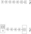
- FIG. 4 shows a flowchart of a method according to the invention for monitoring an electrical consumer in a power grid with three external conductors.
- the method can be used, for example, with the monitoring system 80 according to the invention 3 be performed.
- Step 200 the consumer is connected to the power grid via an intermediate module according to the invention.
- Step 200 includes connecting 200a the intermediate module to the power grid and connecting 200b the load to the intermediate module.
- a receiver module preferably according to the invention, connected to the mains.
- the consumer can then be operated on the power grid.
- operating data of the consumer are determined in the intermediate module and, in a step 206 , information about the determined operating data is transmitted to the power grid via the input power connection of the intermediate module. This information is received in a step 208 by the receiver module from the power grid.
- the information about the operating data can be stored in a step 210 in the receiver module and/or evaluated in a step 212 in the receiver module.
- figure 5 shows a flow chart of a method according to the invention for starting up an intermediate module according to the invention with a connection for a camera.
- the intermediate module is connected to a power supply system with three outer conductors.
- a consumer is connected to the intermediate module.
- a camera is connected to the intermediate module.
- an image of the consumer is captured with the camera.
- this image is then transmitted to the power grid by means of the intermediate module.
- the image is then compared with other images of known consumer types in order to identify the consumer.
- Step 310 can be carried out in a receiver module according to the invention or in a higher-level entity. In the latter case, the image can be transmitted to the superior entity by the receiver module.
- the assignment of the intermediate module and the recognized consumer type is saved. The storage can take place in the superordinate entity and/or a receiver module and/or the intermediate module.
Landscapes
- Engineering & Computer Science (AREA)
- Power Engineering (AREA)
- Physics & Mathematics (AREA)
- General Physics & Mathematics (AREA)
- Remote Monitoring And Control Of Power-Distribution Networks (AREA)
Claims (15)
- Système de surveillance (80) d'une installation de fabrication par usinage du métal et/ou de la tôle permettant de surveiller un consommateur électrique (92a, 92b), comprenant- le consommateur (92a, 92b) sous forme d'une machine de fabrication destinée à l'usinage de la tôle et/ou du métal,- un réseau électrique (82) avec trois conducteurs externes (84a-c),- un module intermédiaire (10) au moyen duquel le consommateur (92a, 92b) peut être connecté au réseau électrique (82), comportant une connexion électrique d'entrée (12) permettant de connecter le module intermédiaire (10) au réseau électrique (82), dans lequel la connexion électrique d'entrée (12) comporte trois contacts d'entrée (16a-c) des conducteurs externes permettant de contacter respectivement un conducteur externe (84a-c) au réseau électrique (82), et comportant une connexion électrique de sortie (24) permettant de connecter le consommateur (92a, 92b) au module intermédiaire (10), dans lequel le module intermédiaire (10) est conçu pour déterminer les données de service du consommateur (92a, 92b) et pour transmettre des informations sur les données de service déterminées au réseau électrique (82) par l'intermédiaire de la connexion électrique d'entrée (12), dans lequel le module intermédiaire (10) est conçu pour mesurer au moins un paramètre d'un courant électrique, lequel circule pendant le fonctionnement du réseau électrique (82) à travers le module intermédiaire (10) vers le consommateur (92a, 92b),- un module récepteur (50) permettant de recevoir du réseau électrique (82) des informations sur les données de service du consommateur (92a, 92b),dans lequel le module récepteur (50) comporte une connexion électrique (52) récepteur permettant de connecter le module récepteur (50) au réseau électrique (82), et un dispositif de traitement (60), lequel est conçu pour recevoir par l'intermédiaire de la connexion électrique (52) récepteur les informations sur les données de service provenant du réseau électrique (82),dans lequel le module intermédiaire (10) comporte une connexion (44) pour une caméra et est conçu pour transmettre au réseau électrique (82) une image reçue de la caméra.
- Système de surveillance (80) selon la revendication 1, caractérisé en ce que le module intermédiaire (10) est conçu pour transmettre les informations sur les données de service par l'intermédiaire d'exactement un des contacts d'entrée (16a-c) des conducteurs externes.
- Système de surveillance (80) selon la revendication 1 ou 2, caractérisé en ce que le module intermédiaire (10) est conçu pour transmettre les informations sur les données de service par l'intermédiaire d'au moins deux, de préférence par l'intermédiaire de tous les contacts d'entrée (16a-c) des conducteurs externes.
- Système de surveillance (80) selon l'une quelconque des revendications précédentes, caractérisé en ce que la connexion électrique d'entrée (12) est conçue sous forme d'une fiche (14) module intermédiaire destinée à être enfichée dans une prise électrique (92a, 92b), en particulier dans lequel les contacts d'entrée (16a-c, 18, 20) de la connexion électrique d'entrée (12) sont respectivement conçus sous la forme d'une fiche mâle (22a-e).
- Système de surveillance (80) selon l'une quelconque des revendications précédentes, caractérisé en ce que la connexion électrique de sortie (24) comporte un contact de sortie (26a-c, 28, 30) associé respectivement à chacun des contacts d'entrée (16a-c, 18, 20) de la connexion électrique d'entrée (12).
- Système de surveillance (80) selon l'une quelconque des revendications précédentes, caractérisé en ce que la connexion électrique de sortie (24) est conçue sous la forme d'une prise électrique (32) module intermédiaire permettant d'enficher une fiche, en particulier dans lequel les contacts de sortie (26a-c, 28, 30) de la connexion électrique de sortie (24) sont respectivement conçus sous la forme d'une douille enfichable (34a-e).
- Système de surveillance (80) selon l'une quelconque des revendications précédentes, caractérisé en ce que le module intermédiaire (10) est conçu pour déterminer les données de service de manière résolue dans le temps, et en ce que les informations sur les données de service déterminées comprennent des informations temporelles.
- Système de surveillance (80) selon l'une quelconque des revendications précédentes, caractérisé en ce que le module intermédiaire (10) est conçu pour recevoir, par l'intermédiaire de la connexion électrique d'entrée (12), des instructions provenant du réseau électrique (82).
- Système de surveillance (80) selon l'une quelconque des revendications précédentes, caractérisé en ce que le module intermédiaire (10) comporte une interface LAN (40) et/ou une interface WLAN (38).
- Système de surveillance (80) selon l'une quelconque des revendications précédentes, caractérisé en ce que le dispositif de traitement (60) est en contact électrique direct avec la connexion électrique (52) du récepteur et est conçu pour enregistrer et/ou évaluer les informations sur les données de service.
- Système de surveillance (80) selon l'une quelconque des revendications précédentes, caractérisé en ce que le module récepteur (50) est conçu pour envoyer des messages relatifs aux informations sur les données de service à un appareil mobile d'un utilisateur.
- Système de surveillance (80) selon l'une quelconque des revendications précédentes, caractérisé en ce que le module récepteur (50) est conçu pour recevoir des instructions, en particulier provenant d'un appareil mobile d'un utilisateur, et pour transmettre lesdites instructions au réseau électrique (82) par l'intermédiaire de la connexion électrique (52) du récepteur.
- Système de surveillance (80) selon l'une quelconque des revendications précédentes, caractérisé en ce
que le réseau électrique (82) comprend en outre un conducteur neutre (86), que la connexion électrique (52) du récepteur du module récepteur (50) comporte un contact de conducteur externe (54) du récepteur permettant de connecter le module récepteur (50) à l'un des conducteurs externes (84a-c) du réseau électrique (82) et un contact de conducteur neutre (56) du récepteur permettant de connecter le module récepteur (50) au conducteur neutre (86) du réseau électrique (82). - Utilisation d'un système de surveillance (80) selon l'une quelconque des revendications 1 à 13 permettant de surveiller le consommateur (92a, 92b) électrique sous la forme d'une machine de fabrication destinée au traitement de la tôle et/ou du métal, dans laquelle le consommateur (92a, 92b) est connecté par l'intermédiaire du module intermédiaire (10) au réseau électrique (82) à l'aide de trois conducteurs externes (84a-c).
- Procédé de surveillance d'une machine de fabrication dans une installation de fabrication comportant le système de surveillance selon l'une quelconque des revendications 1 à 13, dans lequel la machine de fabrication peut être connectée comme consommateur (92a, 92b) électrique à un réseau électrique (82) à l'aide de trois conducteurs externes (84a-c), comportant les étapes suivantesa) connexion (200) de la machine de fabrication, par l'intermédiaire du module intermédiaire (10), au réseau électrique (82), dans lequel le module intermédiaire (10) comporte la connexion électrique d'entrée (12) permettant de connecter le module intermédiaire (10) au réseau électrique (82) et la connexion électrique de sortie (24) permettant de connecter la machine à usiner au module intermédiaire (10), dans lequel le module intermédiaire (10) est conçu pour déterminer des données de service de la machine de fabrication et pour transmettre, par l'intermédiaire de la connexion électrique d'entrée (12), des informations au réseau électrique (82) sur les données de service déterminées, et dans lequel la connexion électrique d'entrée (12) comporte trois contacts d'entrée (16a-c) des conducteurs externes permettant de contacter respectivement un conducteur externe (84a-c) du réseau électrique (82),b) connexion (202) du module récepteur (50) au réseau électrique (82),c) détermination (204) des données de service du consommateur (92a, 92b) dans le module intermédiaire (10) et transmission (206) au réseau électrique (82) des informations sur les données de service déterminées par l'intermédiaire de la connexion électrique d'entrée (12) du module intermédiaire (10),d) réception (108) dans le module récepteur (50) des informations sur les données de service provenant du réseau électrique (82),e) enregistrement (210) et/ou évaluation (212) dans le module récepteur (50) des informations sur les données de service.
Applications Claiming Priority (2)
| Application Number | Priority Date | Filing Date | Title |
|---|---|---|---|
| DE102018205492.4A DE102018205492A1 (de) | 2018-04-11 | 2018-04-11 | Zwischenmodul, Empfängermodul, Überwachungssystem und Überwachungsverfahren |
| PCT/EP2019/059036 WO2019197443A1 (fr) | 2018-04-11 | 2019-04-10 | Module intermédiaire, module récepteur, système de surveillance et procédé de surveillance |
Publications (2)
| Publication Number | Publication Date |
|---|---|
| EP3775942A1 EP3775942A1 (fr) | 2021-02-17 |
| EP3775942B1 true EP3775942B1 (fr) | 2023-06-07 |
Family
ID=66182529
Family Applications (1)
| Application Number | Title | Priority Date | Filing Date |
|---|---|---|---|
| EP19717818.9A Active EP3775942B1 (fr) | 2018-04-11 | 2019-04-10 | Module intermédiaire, module récepteur, système de surveillance et procédé de surveillance |
Country Status (4)
| Country | Link |
|---|---|
| EP (1) | EP3775942B1 (fr) |
| CN (1) | CN111954822B (fr) |
| DE (1) | DE102018205492A1 (fr) |
| WO (1) | WO2019197443A1 (fr) |
Families Citing this family (2)
| Publication number | Priority date | Publication date | Assignee | Title |
|---|---|---|---|---|
| DE102020213966A1 (de) | 2020-11-06 | 2022-06-02 | Trumpf Werkzeugmaschinen Gmbh + Co. Kg | Mobile Kommunikationseinrichtung und mit der mobilen Kommunikationseinrichtung kontrollierbare Werkzeugmaschine |
| DE102022103875A1 (de) | 2022-02-18 | 2023-08-24 | TRUMPF Werkzeugmaschinen SE + Co. KG | Verfahren und System zur Bestimmung eines Betriebszustandes einer Maschine |
Family Cites Families (23)
| Publication number | Priority date | Publication date | Assignee | Title |
|---|---|---|---|---|
| DE4425876A1 (de) * | 1994-07-09 | 1996-01-11 | Wolfgang Dipl Jur Reimann | Intelligente Steckdose |
| JP2004362070A (ja) * | 2003-06-02 | 2004-12-24 | Idemitsu Kosan Co Ltd | コージェネレーショングリッド燃料自動発注・配送システム |
| AT504670B1 (de) * | 2006-11-28 | 2008-07-15 | Keba Ag | Verfahren zum betreiben einer drahtlosen kommunikationsverbindung zwischen einem mobilen handbediengerät und einer maschinensteuerung sowie entsprechende systemkomponenten |
| CN101321071A (zh) * | 2008-06-03 | 2008-12-10 | 胡钊洪 | Poe开关电源适配器 |
| CN201398080Y (zh) * | 2009-02-26 | 2010-02-03 | 上海久电科技开发有限公司 | 低压配电网络负荷测录及无功调节装置 |
| JP2013517756A (ja) * | 2010-01-15 | 2013-05-16 | ジー4 シナジェティクス, インコーポレイテッド | 充電の状態を測定する方法およびシステム |
| DE202010000364U1 (de) * | 2010-03-12 | 2010-05-27 | EnBW Energie Baden-Württemberg AG | Kontaktlose Strommessvorrichtung und Verbraucherenergiemesssystem |
| CN102201252B (zh) * | 2010-03-26 | 2014-04-30 | 鸿富锦精密工业(深圳)有限公司 | 存储装置连接结构 |
| PT105189B (pt) * | 2010-07-07 | 2014-12-12 | Afonso Domingos Brito Santos | Módulo autónomo de produção, regulação, armazenamento, ondulação e distribuição de energia eléctrica fotovoltaica e método de controlo e gestão das comunicações entre módulos quando inseridos numa rede |
| DE202010011570U1 (de) * | 2010-08-19 | 2010-11-18 | Thyssenkrupp Steel Europe Ag | Teilautomatisierte Drehfrequenzsteuerung |
| WO2012136843A1 (fr) * | 2011-04-08 | 2012-10-11 | Sma Solar Technology Ag | Gestion de charge optimisée |
| CN102590610B (zh) * | 2012-02-27 | 2014-11-19 | 华立仪表集团股份有限公司 | 智能一体式多功能电能表及其对负载的控制方法 |
| CN202679480U (zh) * | 2012-04-17 | 2013-01-16 | 深圳市度申科技有限公司 | 一种cfs工业相机 |
| GB2505929A (en) * | 2012-09-14 | 2014-03-19 | Pod Point Holiding Ltd | Method and system for predictive load shedding on a power grid |
| DE202012009494U1 (de) * | 2012-10-02 | 2012-10-10 | Abb Ag | Personen-Anwesenheitserkennungs-Netzwerk mit einer Vielzahl von Geräten der Hausinstallation / Gebäudesystemtechnik |
| DE102014221108A1 (de) * | 2013-10-17 | 2015-04-23 | Power Plus Communications Ag | Koppeleinrichtung zum Ankoppeln eines Powerline-Endgeräts und eines Messgeräts an ein Energieversorgungsnetzwerk sowie Messknoten |
| KR101424417B1 (ko) * | 2014-02-10 | 2014-07-28 | 이셀전자 주식회사 | 카메라가 구비된 헬멧 |
| CN205027924U (zh) * | 2015-10-19 | 2016-02-10 | 国家海洋局第一海洋研究所 | 一种轻便型、耐腐蚀式海岸带陆地自动气象站 |
| CN105845255A (zh) * | 2016-05-17 | 2016-08-10 | 宁波博禄德电子有限公司 | 一种组合型usb数据线 |
| DE102016113028A1 (de) * | 2016-07-14 | 2018-01-18 | Maxsyma GmbH & Co.KG | System zur überwachung des energieverbrauchs in industrieanlagen und energiemess – und übertragungsmodul hierfür |
| CN205911811U (zh) * | 2016-07-18 | 2017-01-25 | 天津斌德鑫力电子科技有限公司 | 一种动车组多通道智能维保辅助供电系统 |
| CN106130164B (zh) * | 2016-07-18 | 2018-12-04 | 天津斌德鑫力电子科技有限公司 | 一种动车组维保辅助供电系统 |
| CN206725732U (zh) * | 2017-05-24 | 2017-12-08 | 重庆大学 | 燃料电池远程监测与控制系统 |
-
2018
- 2018-04-11 DE DE102018205492.4A patent/DE102018205492A1/de not_active Withdrawn
-
2019
- 2019-04-10 EP EP19717818.9A patent/EP3775942B1/fr active Active
- 2019-04-10 CN CN201980024606.XA patent/CN111954822B/zh active Active
- 2019-04-10 WO PCT/EP2019/059036 patent/WO2019197443A1/fr not_active Ceased
Also Published As
| Publication number | Publication date |
|---|---|
| WO2019197443A1 (fr) | 2019-10-17 |
| DE102018205492A1 (de) | 2019-10-17 |
| CN111954822A (zh) | 2020-11-17 |
| CN111954822B (zh) | 2024-07-05 |
| EP3775942A1 (fr) | 2021-02-17 |
Similar Documents
| Publication | Publication Date | Title |
|---|---|---|
| EP2697888B1 (fr) | Méthode de détermination de la topologie d'un réseau de distribution basse tension | |
| DE10037968B4 (de) | Elektrischer Antrieb mit Motoridentifizierung und Verfahren zur Motoridentifizierung | |
| EP2992391A1 (fr) | Module d'interface électrique | |
| EP4345555B1 (fr) | Procédé de contrôle assisté par ordinateur et documentation d'une action d'installation d'un utilisateur pour installer des composants d'une machine agencés de manière spatiale | |
| DE102022123571B3 (de) | System zur betätigung eines stufenschalters | |
| EP3775942B1 (fr) | Module intermédiaire, module récepteur, système de surveillance et procédé de surveillance | |
| EP1611777B1 (fr) | Module basse tension | |
| WO2021160756A1 (fr) | Agencement d'évaluation de l'état et de la qualité de réseaux à basses tensions | |
| EP1999526A1 (fr) | Gestion d'un bus de terrain sans fil | |
| EP3772796B1 (fr) | Supports de barres omnibus et tableaux de répartition | |
| WO2014177482A1 (fr) | Module d'interface électrique | |
| EP2960664B1 (fr) | Système d'enregistrement de puissances et de quantités d'énergie dans des conducteurs | |
| EP2555003B1 (fr) | Transducteur de courant et sectionneur de charge étant équipé avec celui-ci | |
| WO2007022828A2 (fr) | Systeme modulaire a puissance necessaire controlee | |
| EP3126991A1 (fr) | Module d'interface électrique | |
| EP3759505B1 (fr) | Procédé d'évaluation de l'état et de la qualité de réseaux basse tension | |
| EP3805880A1 (fr) | Commande pour un outil et une machine-outil compatible à l'outil ainsi que procédé de fonctionnement d'une commande | |
| EP3741027B1 (fr) | Équipement à haute ou moyenne tension | |
| EP2073335A2 (fr) | Appareil d'installation électrique | |
| EP2781005A1 (fr) | Réseau de distribution d'énergie | |
| DE19703160B4 (de) | Einrichtung zum Verbinden und Betreiben von Protokolliereinrichtungen in einer EIB-Anlage | |
| EP4169052B1 (fr) | Base pour composant électrique/électronique | |
| EP2384422A2 (fr) | Module de compteur de courant multiphasé | |
| EP1196829A1 (fr) | Module de commande d'un mecanisme d'entrainement | |
| WO2024068899A1 (fr) | Procédé de fourniture assistée par ordinateur d'une spécification d'adaptation pour une technologie d'installation électrotechnique |
Legal Events
| Date | Code | Title | Description |
|---|---|---|---|
| STAA | Information on the status of an ep patent application or granted ep patent |
Free format text: STATUS: UNKNOWN |
|
| STAA | Information on the status of an ep patent application or granted ep patent |
Free format text: STATUS: THE INTERNATIONAL PUBLICATION HAS BEEN MADE |
|
| PUAI | Public reference made under article 153(3) epc to a published international application that has entered the european phase |
Free format text: ORIGINAL CODE: 0009012 |
|
| STAA | Information on the status of an ep patent application or granted ep patent |
Free format text: STATUS: REQUEST FOR EXAMINATION WAS MADE |
|
| 17P | Request for examination filed |
Effective date: 20200821 |
|
| AK | Designated contracting states |
Kind code of ref document: A1 Designated state(s): AL AT BE BG CH CY CZ DE DK EE ES FI FR GB GR HR HU IE IS IT LI LT LU LV MC MK MT NL NO PL PT RO RS SE SI SK SM TR |
|
| AX | Request for extension of the european patent |
Extension state: BA ME |
|
| DAV | Request for validation of the european patent (deleted) | ||
| DAX | Request for extension of the european patent (deleted) | ||
| GRAP | Despatch of communication of intention to grant a patent |
Free format text: ORIGINAL CODE: EPIDOSNIGR1 |
|
| STAA | Information on the status of an ep patent application or granted ep patent |
Free format text: STATUS: GRANT OF PATENT IS INTENDED |
|
| INTG | Intention to grant announced |
Effective date: 20230302 |
|
| RAP3 | Party data changed (applicant data changed or rights of an application transferred) |
Owner name: TRUMPF WERKZEUGMASCHINEN SE + CO. KG |
|
| GRAS | Grant fee paid |
Free format text: ORIGINAL CODE: EPIDOSNIGR3 |
|
| GRAA | (expected) grant |
Free format text: ORIGINAL CODE: 0009210 |
|
| STAA | Information on the status of an ep patent application or granted ep patent |
Free format text: STATUS: THE PATENT HAS BEEN GRANTED |
|
| AK | Designated contracting states |
Kind code of ref document: B1 Designated state(s): AL AT BE BG CH CY CZ DE DK EE ES FI FR GB GR HR HU IE IS IT LI LT LU LV MC MK MT NL NO PL PT RO RS SE SI SK SM TR |
|
| REG | Reference to a national code |
Ref country code: GB Ref legal event code: FG4D Free format text: NOT ENGLISH |
|
| REG | Reference to a national code |
Ref country code: CH Ref legal event code: EP Ref country code: AT Ref legal event code: REF Ref document number: 1576692 Country of ref document: AT Kind code of ref document: T Effective date: 20230615 Ref country code: DE Ref legal event code: R096 Ref document number: 502019008026 Country of ref document: DE |
|
| REG | Reference to a national code |
Ref country code: LT Ref legal event code: MG9D |
|
| REG | Reference to a national code |
Ref country code: NL Ref legal event code: MP Effective date: 20230607 |
|
| PG25 | Lapsed in a contracting state [announced via postgrant information from national office to epo] |
Ref country code: SE Free format text: LAPSE BECAUSE OF FAILURE TO SUBMIT A TRANSLATION OF THE DESCRIPTION OR TO PAY THE FEE WITHIN THE PRESCRIBED TIME-LIMIT Effective date: 20230607 Ref country code: NO Free format text: LAPSE BECAUSE OF FAILURE TO SUBMIT A TRANSLATION OF THE DESCRIPTION OR TO PAY THE FEE WITHIN THE PRESCRIBED TIME-LIMIT Effective date: 20230907 Ref country code: ES Free format text: LAPSE BECAUSE OF FAILURE TO SUBMIT A TRANSLATION OF THE DESCRIPTION OR TO PAY THE FEE WITHIN THE PRESCRIBED TIME-LIMIT Effective date: 20230607 |
|
| PG25 | Lapsed in a contracting state [announced via postgrant information from national office to epo] |
Ref country code: RS Free format text: LAPSE BECAUSE OF FAILURE TO SUBMIT A TRANSLATION OF THE DESCRIPTION OR TO PAY THE FEE WITHIN THE PRESCRIBED TIME-LIMIT Effective date: 20230607 Ref country code: NL Free format text: LAPSE BECAUSE OF FAILURE TO SUBMIT A TRANSLATION OF THE DESCRIPTION OR TO PAY THE FEE WITHIN THE PRESCRIBED TIME-LIMIT Effective date: 20230607 Ref country code: LV Free format text: LAPSE BECAUSE OF FAILURE TO SUBMIT A TRANSLATION OF THE DESCRIPTION OR TO PAY THE FEE WITHIN THE PRESCRIBED TIME-LIMIT Effective date: 20230607 Ref country code: LT Free format text: LAPSE BECAUSE OF FAILURE TO SUBMIT A TRANSLATION OF THE DESCRIPTION OR TO PAY THE FEE WITHIN THE PRESCRIBED TIME-LIMIT Effective date: 20230607 Ref country code: HR Free format text: LAPSE BECAUSE OF FAILURE TO SUBMIT A TRANSLATION OF THE DESCRIPTION OR TO PAY THE FEE WITHIN THE PRESCRIBED TIME-LIMIT Effective date: 20230607 Ref country code: GR Free format text: LAPSE BECAUSE OF FAILURE TO SUBMIT A TRANSLATION OF THE DESCRIPTION OR TO PAY THE FEE WITHIN THE PRESCRIBED TIME-LIMIT Effective date: 20230908 |
|
| PG25 | Lapsed in a contracting state [announced via postgrant information from national office to epo] |
Ref country code: FI Free format text: LAPSE BECAUSE OF FAILURE TO SUBMIT A TRANSLATION OF THE DESCRIPTION OR TO PAY THE FEE WITHIN THE PRESCRIBED TIME-LIMIT Effective date: 20230607 |
|
| PG25 | Lapsed in a contracting state [announced via postgrant information from national office to epo] |
Ref country code: SK Free format text: LAPSE BECAUSE OF FAILURE TO SUBMIT A TRANSLATION OF THE DESCRIPTION OR TO PAY THE FEE WITHIN THE PRESCRIBED TIME-LIMIT Effective date: 20230607 |
|
| PG25 | Lapsed in a contracting state [announced via postgrant information from national office to epo] |
Ref country code: IS Free format text: LAPSE BECAUSE OF FAILURE TO SUBMIT A TRANSLATION OF THE DESCRIPTION OR TO PAY THE FEE WITHIN THE PRESCRIBED TIME-LIMIT Effective date: 20231007 |
|
| PG25 | Lapsed in a contracting state [announced via postgrant information from national office to epo] |
Ref country code: SM Free format text: LAPSE BECAUSE OF FAILURE TO SUBMIT A TRANSLATION OF THE DESCRIPTION OR TO PAY THE FEE WITHIN THE PRESCRIBED TIME-LIMIT Effective date: 20230607 Ref country code: SK Free format text: LAPSE BECAUSE OF FAILURE TO SUBMIT A TRANSLATION OF THE DESCRIPTION OR TO PAY THE FEE WITHIN THE PRESCRIBED TIME-LIMIT Effective date: 20230607 Ref country code: RO Free format text: LAPSE BECAUSE OF FAILURE TO SUBMIT A TRANSLATION OF THE DESCRIPTION OR TO PAY THE FEE WITHIN THE PRESCRIBED TIME-LIMIT Effective date: 20230607 Ref country code: PT Free format text: LAPSE BECAUSE OF FAILURE TO SUBMIT A TRANSLATION OF THE DESCRIPTION OR TO PAY THE FEE WITHIN THE PRESCRIBED TIME-LIMIT Effective date: 20231009 Ref country code: IS Free format text: LAPSE BECAUSE OF FAILURE TO SUBMIT A TRANSLATION OF THE DESCRIPTION OR TO PAY THE FEE WITHIN THE PRESCRIBED TIME-LIMIT Effective date: 20231007 Ref country code: EE Free format text: LAPSE BECAUSE OF FAILURE TO SUBMIT A TRANSLATION OF THE DESCRIPTION OR TO PAY THE FEE WITHIN THE PRESCRIBED TIME-LIMIT Effective date: 20230607 Ref country code: CZ Free format text: LAPSE BECAUSE OF FAILURE TO SUBMIT A TRANSLATION OF THE DESCRIPTION OR TO PAY THE FEE WITHIN THE PRESCRIBED TIME-LIMIT Effective date: 20230607 |
|
| PG25 | Lapsed in a contracting state [announced via postgrant information from national office to epo] |
Ref country code: PL Free format text: LAPSE BECAUSE OF FAILURE TO SUBMIT A TRANSLATION OF THE DESCRIPTION OR TO PAY THE FEE WITHIN THE PRESCRIBED TIME-LIMIT Effective date: 20230607 |
|
| REG | Reference to a national code |
Ref country code: DE Ref legal event code: R097 Ref document number: 502019008026 Country of ref document: DE |
|
| PLBE | No opposition filed within time limit |
Free format text: ORIGINAL CODE: 0009261 |
|
| STAA | Information on the status of an ep patent application or granted ep patent |
Free format text: STATUS: NO OPPOSITION FILED WITHIN TIME LIMIT |
|
| PG25 | Lapsed in a contracting state [announced via postgrant information from national office to epo] |
Ref country code: DK Free format text: LAPSE BECAUSE OF FAILURE TO SUBMIT A TRANSLATION OF THE DESCRIPTION OR TO PAY THE FEE WITHIN THE PRESCRIBED TIME-LIMIT Effective date: 20230607 |
|
| PG25 | Lapsed in a contracting state [announced via postgrant information from national office to epo] |
Ref country code: SI Free format text: LAPSE BECAUSE OF FAILURE TO SUBMIT A TRANSLATION OF THE DESCRIPTION OR TO PAY THE FEE WITHIN THE PRESCRIBED TIME-LIMIT Effective date: 20230607 |
|
| 26N | No opposition filed |
Effective date: 20240308 |
|
| PG25 | Lapsed in a contracting state [announced via postgrant information from national office to epo] |
Ref country code: SI Free format text: LAPSE BECAUSE OF FAILURE TO SUBMIT A TRANSLATION OF THE DESCRIPTION OR TO PAY THE FEE WITHIN THE PRESCRIBED TIME-LIMIT Effective date: 20230607 Ref country code: IT Free format text: LAPSE BECAUSE OF FAILURE TO SUBMIT A TRANSLATION OF THE DESCRIPTION OR TO PAY THE FEE WITHIN THE PRESCRIBED TIME-LIMIT Effective date: 20230607 |
|
| PG25 | Lapsed in a contracting state [announced via postgrant information from national office to epo] |
Ref country code: BG Free format text: LAPSE BECAUSE OF FAILURE TO SUBMIT A TRANSLATION OF THE DESCRIPTION OR TO PAY THE FEE WITHIN THE PRESCRIBED TIME-LIMIT Effective date: 20230607 |
|
| PG25 | Lapsed in a contracting state [announced via postgrant information from national office to epo] |
Ref country code: MC Free format text: LAPSE BECAUSE OF FAILURE TO SUBMIT A TRANSLATION OF THE DESCRIPTION OR TO PAY THE FEE WITHIN THE PRESCRIBED TIME-LIMIT Effective date: 20230607 |
|
| PG25 | Lapsed in a contracting state [announced via postgrant information from national office to epo] |
Ref country code: MC Free format text: LAPSE BECAUSE OF FAILURE TO SUBMIT A TRANSLATION OF THE DESCRIPTION OR TO PAY THE FEE WITHIN THE PRESCRIBED TIME-LIMIT Effective date: 20230607 Ref country code: BG Free format text: LAPSE BECAUSE OF FAILURE TO SUBMIT A TRANSLATION OF THE DESCRIPTION OR TO PAY THE FEE WITHIN THE PRESCRIBED TIME-LIMIT Effective date: 20230607 |
|
| REG | Reference to a national code |
Ref country code: CH Ref legal event code: PL |
|
| PG25 | Lapsed in a contracting state [announced via postgrant information from national office to epo] |
Ref country code: LU Free format text: LAPSE BECAUSE OF NON-PAYMENT OF DUE FEES Effective date: 20240410 |
|
| GBPC | Gb: european patent ceased through non-payment of renewal fee |
Effective date: 20240410 |
|
| REG | Reference to a national code |
Ref country code: BE Ref legal event code: MM Effective date: 20240430 |
|
| PG25 | Lapsed in a contracting state [announced via postgrant information from national office to epo] |
Ref country code: LU Free format text: LAPSE BECAUSE OF NON-PAYMENT OF DUE FEES Effective date: 20240410 |
|
| PG25 | Lapsed in a contracting state [announced via postgrant information from national office to epo] |
Ref country code: BE Free format text: LAPSE BECAUSE OF NON-PAYMENT OF DUE FEES Effective date: 20240430 |
|
| PG25 | Lapsed in a contracting state [announced via postgrant information from national office to epo] |
Ref country code: GB Free format text: LAPSE BECAUSE OF NON-PAYMENT OF DUE FEES Effective date: 20240410 |
|
| PG25 | Lapsed in a contracting state [announced via postgrant information from national office to epo] |
Ref country code: FR Free format text: LAPSE BECAUSE OF NON-PAYMENT OF DUE FEES Effective date: 20240430 |
|
| PG25 | Lapsed in a contracting state [announced via postgrant information from national office to epo] |
Ref country code: GB Free format text: LAPSE BECAUSE OF NON-PAYMENT OF DUE FEES Effective date: 20240410 Ref country code: FR Free format text: LAPSE BECAUSE OF NON-PAYMENT OF DUE FEES Effective date: 20240430 Ref country code: BE Free format text: LAPSE BECAUSE OF NON-PAYMENT OF DUE FEES Effective date: 20240430 Ref country code: CH Free format text: LAPSE BECAUSE OF NON-PAYMENT OF DUE FEES Effective date: 20240430 |
|
| PG25 | Lapsed in a contracting state [announced via postgrant information from national office to epo] |
Ref country code: IE Free format text: LAPSE BECAUSE OF NON-PAYMENT OF DUE FEES Effective date: 20240410 |
|
| REG | Reference to a national code |
Ref country code: AT Ref legal event code: MM01 Ref document number: 1576692 Country of ref document: AT Kind code of ref document: T Effective date: 20240410 |
|
| PGFP | Annual fee paid to national office [announced via postgrant information from national office to epo] |
Ref country code: DE Payment date: 20250422 Year of fee payment: 7 |
|
| PG25 | Lapsed in a contracting state [announced via postgrant information from national office to epo] |
Ref country code: AT Free format text: LAPSE BECAUSE OF NON-PAYMENT OF DUE FEES Effective date: 20240410 |
|
| PG25 | Lapsed in a contracting state [announced via postgrant information from national office to epo] |
Ref country code: CY Free format text: LAPSE BECAUSE OF FAILURE TO SUBMIT A TRANSLATION OF THE DESCRIPTION OR TO PAY THE FEE WITHIN THE PRESCRIBED TIME-LIMIT; INVALID AB INITIO Effective date: 20190410 |
|
| PG25 | Lapsed in a contracting state [announced via postgrant information from national office to epo] |
Ref country code: HU Free format text: LAPSE BECAUSE OF FAILURE TO SUBMIT A TRANSLATION OF THE DESCRIPTION OR TO PAY THE FEE WITHIN THE PRESCRIBED TIME-LIMIT; INVALID AB INITIO Effective date: 20190410 |