EP3775955B1 - Fers à cale pour appareil à résonance magnétique - Google Patents
Fers à cale pour appareil à résonance magnétique Download PDFInfo
- Publication number
- EP3775955B1 EP3775955B1 EP19713520.5A EP19713520A EP3775955B1 EP 3775955 B1 EP3775955 B1 EP 3775955B1 EP 19713520 A EP19713520 A EP 19713520A EP 3775955 B1 EP3775955 B1 EP 3775955B1
- Authority
- EP
- European Patent Office
- Prior art keywords
- shim
- plates
- slits
- iron
- slit
- Prior art date
- Legal status (The legal status is an assumption and is not a legal conclusion. Google has not performed a legal analysis and makes no representation as to the accuracy of the status listed.)
- Active
Links
Images


Classifications
-
- G—PHYSICS
- G01—MEASURING; TESTING
- G01R—MEASURING ELECTRIC VARIABLES; MEASURING MAGNETIC VARIABLES
- G01R33/00—Arrangements or instruments for measuring magnetic variables
- G01R33/20—Arrangements or instruments for measuring magnetic variables involving magnetic resonance
- G01R33/28—Details of apparatus provided for in groups G01R33/44 - G01R33/64
- G01R33/38—Systems for generation, homogenisation or stabilisation of the main or gradient magnetic field
- G01R33/3802—Manufacture or installation of magnet assemblies; Additional hardware for transportation or installation of the magnet assembly or for providing mechanical support to components of the magnet assembly
-
- G—PHYSICS
- G01—MEASURING; TESTING
- G01R—MEASURING ELECTRIC VARIABLES; MEASURING MAGNETIC VARIABLES
- G01R33/00—Arrangements or instruments for measuring magnetic variables
- G01R33/20—Arrangements or instruments for measuring magnetic variables involving magnetic resonance
- G01R33/28—Details of apparatus provided for in groups G01R33/44 - G01R33/64
- G01R33/38—Systems for generation, homogenisation or stabilisation of the main or gradient magnetic field
- G01R33/387—Compensation of inhomogeneities
- G01R33/3873—Compensation of inhomogeneities using ferromagnetic bodies ; Passive shimming
Definitions
- the invention relates to the field of shim irons for use with a magnetic resonance (MR) apparatus, and in particular to shim irons which are comprised of a stack of shim plates which are slit in order to reduce heating of the shim irons due to eddy currents.
- MR magnetic resonance
- NMR nuclear magnetic resonance
- MRI magnetic resonance imaging
- shimming is used prior to the operation of the magnet to eliminate inhomogeneities in its static magnetic field.
- the magnetic field inside an NMR spectrometer or MRI scanner is far from homogeneous compared with an "ideal" field of the device. This is a result of production tolerances and of the environment of the scanner. Iron constructions in walls and floor of the examination room become magnetized and disturb the field of the scanner. The probe and the sample or the patient become slightly magnetized when brought into the strong magnetic field and create additional inhomogeneous fields.
- the process of correcting for these inhomogeneities is called shimming the magnet, shimming the probe or shimming the sample, depending on the assumed source of the remaining inhomogeneity.
- Field homogeneity of the order of 1 ppm over a volume of several liters is needed in an MRI scanner.
- High-resolution NMR spectroscopy demands field homogeneity better than 1 ppb within a volume of a few milliliters.
- active shimming uses coils with adjustable current.
- Passive shimming involves pieces of steel with suitable magnetic properties, also called shim irons. The shim irons are placed near the permanent or superconducting magnet. They become magnetized and produce their own magnetic field. In both cases, the additional magnetic fields from the coils or shim irons, respectively, add to the overall magnetic field of the superconducting magnet in such a way as to increase the homogeneity of the total field.
- a MRI scanner comprises a field-generating unit (both B0+gradients), which has openings along the longitudinal axis into which shim rails are inserted. These shim rails have various pockets into which shim irons are placed.
- shim irons are typically placed at locations where the gradient field is close to maximum. Further, in such a configuration, the shim irons are mechanically connected to the gradient-generating unit which is prone to vibration, rather than to the BO-generating unit (the inner hull of the cryostat), which is rather static. Therefore, the recent deployment of such MRI scanners leads to an aggravation of a problem long known, i.e. the heating of the shim irons and hence the thermal drift of the shimming.
- Shim plates provided with a cut (or slit) for suppression of eddy currents are known per se from the Japanese utility model JP-H09-238917 .
- a shim iron for use with a magnetic resonance (MR) apparatus wherein the shim iron is comprised of a stack of shim plates, wherein at least two of the shim plates comprise slits, the slits forming a respective slit pattern of the shim plates, and wherein of shim plates that are consecutive in the stack at least some of the slits are oriented differently, to avoid that they coincide.
- MR magnetic resonance
- the slits of the respective slit patterns of consecutive shim plates have different orientations in the plane of the shim plates, there are no slits of the respective shim plate that coincide, i.e. fall on top of each other, in the stack. This avoids that constructive superposition occurs of eddy currents in consecutive shim plates. Hence, heating due to eddy currents in the stack is counteracted, so that the shim iron is hardly sensitive to heating due to eddy currents in its plates.
- the different orientations of the slit patterns of consecutive shim plates may be achieved by providing different shim patterns of the respective shim plates that are not congruent for in-plane rotation over the plates' shape rotational symmetry angles.
- the slits of the respective pattern do not coincide, independently of the plates having orientations that differ by a rotational symmetry angle of the plates' shape.
- their slit pattern do not show coincident slits.
- An implementation that is particularly simple to manufacture is achieved by providing for respective shim plates a single slit pattern that has a rotational symmetry with respect to a rotational axis that is in-plane offset from the axis of rotation of the plate's shape rotational symmetry.
- the invention proposes to use shim plates with different types of slitting.
- the basic idea is to have different slitting patterns in every consecutive plate, so that by stacking the plates the slits do not coincide.
- the invention allows that only part of the shim plates of the shim iron comprise slits.
- all of the shim plates comprise slits.
- the shim plates could be of different shapes.
- the shim plates all have the same shape, which preferably is a rectangular shape. As set out further below, this allows for correct alignment of the slit patterns of the shim plates in an easy and reliable way when assembling a shim iron.
- rectangular shim plates could have the shape of squares, according to a preferred embodiment of the invention, the s rectangular him plates have sides with different lengths. This makes correct alignment of the shim plates even easier.
- the positive effect of the invention may be achieved with different shapes of the slits themselves.
- the slits all run straight.
- the shim plates could have different thicknesses, according to a preferred embodiment of the invention all shim plates have the same thickness.
- the shim plates could also be made from different magnetizable materials. However, it is preferred that the shim plates are all made from the same magnetizable material.
- consecutive shim plates are galvanically insulated from each other, preferably by insulation sheets having the same shape as the shim plates.
- all shim plates are slit in the same way, wherein the slit pattern, when viewed from one side of a respective shim plate, is different from the slit pattern when viewed from the other side of the shim plate.
- the slit pattern is preferably asymmetric.
- the slit patterns are comprised of at least two different slit patterns which may not be brought into congruent coverage with each other. This means that the slit patterns are always different, no matter to which side a shim plate is turned or from which side it is viewed. With at least two different slit pattern which are shaped in this way a stack of shim plates may be assembled for which the slit patterns of consecutive shim plates are not in congruent coverage with each other.
- all slit patterns comprise the same number of straight slits, the straight slits having the same relative angels to each other, wherein the orientation of the slits of the slit pattern of a second shim plate is given by an integer number of non-rational angle rotations, preferably Golden Angle rotations of each slit of the slit pattern of a first shim plate.
- the Golden Angle is the smaller of the two angles created by sectioning the circumference of a circle according to the golden ratio, i.e. into two arcs such that the ratio of the length of the larger arc to the length of the smaller arc is the same as the ratio of the full circumference to the length of the larger arc.
- the Golden Angel can be approximated in degrees as 137.508°. In this way, it may be achieved in an easy and reliable way that the slit patterns of all shim plates of a shim iron, when viewed from the same viewing direction, are all different from each other.
- the invention further relates to a shim rail with a plurality of pockets, wherein at least one pocket comprises a shim iron as described before.
- the invention also relates to a MRI apparatus with a bore for accommodating a subject to examined and a field-generating unit surrounding the bore, wherein the field-generating unit comprises a plurality of openings which run parallel to the longitudinal axis of the bore and wherein at least one of the plurality of bores comprises a shim rail as described before.
- the invention also relates to a method of shimming a MRI apparatus with at least one shim iron, comprising the following method steps:
- the method comprises the additional method step of:
- the invention also relates to a method of manufacturing a shim plate for a shim iron which is to be used in a MRI apparatus, comprising the following steps:
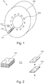
- Fig. 1 schematically shows a MRI scanner 10 according to a preferred embodiment of the invention. It comprises of a field-generating unit 100 (both B0+gradients), which has openings 110 along the longitudinal axis, into which shim rails 111 are inserted. These shim rails 111 have various pockets 120 into which shim irons 130 are placed.
- shim irons 130 in the form of blocks or stacks of slit shim plates 132, 133 as shown in Fig. 2 are placed.
- the amount of shim plates 132 per pocket 120 is determined in several iteration rounds to make the B0 field most homogeneous.
- a part of the so called shimming procedure is done on the customer site to compensate for ferromagnetic building parts and equipment in the vicinity of the MRI scanner 10.
- Fig. 3 shows an enlarged cross-sectional view of a part of the field-generating unit 100. It consists of an outer part of a BO-generating unit 111 (preferably a superconducting coil within a cryostat), into which a gradient-generating unit 113 is mounted.
- the gradient-generating unit 113 consists of a gradient coil 116 which is preferably actively shielded by a shielding coil 114, and a spacer 115 is located between them.
- Fig. 4 shows possible locations for a cylindrically shaped layer 117 into which the shim rails 111 with the shim irons 130 are mounted.
- option A is used in older scanners
- option C is preferably used for the present preferred embodiment of the invention.
- Option C is chosen for its better space usage, allowing larger free-bore diameters (e.g. 70cm) and hence accessibility also to obese patients. This space usage stems from the fact, that the spacer 115 is needed anyhow to separate coils 114 and 116, so this space can be used for the shim-iron layer 117, rather than wasted, as in all the other options.
- the shim irons 130 are placed at the location where the gradient field is maximum.
- the shim irons 130 are mechanically connected to the gradient-generating unit 113, which is prone to vibration, rather than to the BO-generating unit 111 (the inner hull of the cryostat), which is rather static. Therefore, option C in MRI scanners leads to an aggravation of a problem long known, i.e. the heating up of the shim irons and hence the thermal drift of the shimming.
- this problem is addressed by using slit shim plates 132, 133 wherein neighboring shim plates132, 133 comprise such slit patterns which are not congruent to each other.
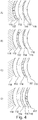
- An example of such slit patterns is shown in Fig. 5 .
- two types of slit patterns for the shim plates 132, 133 is provided.
- shim irons 130 may be stacked in which neighboring shim plates 132, 133 do not comprises congruent slit patterns. In this way, eddy currents in these shim irons 132, 133 are reduced and, hence, heating of the shim irons 130 is reduced.
- Shim irons 130 in which neighboring shim plates 132, 133 do not comprises congruent slit patterns may also be stacked with the help of shim plates 134 which all comprise the same asymmetric slit pattern as shown in Fig. 6 .
- shim plate 134 which provides - from the same viewing angle - four different non-congruent slit patterns by turning the shim plate 134 from its back side to its front side and by turning the shim plate 134 by 180° along its normal axis which is indicated by "front” and “back” as well as “1", "2", “3", and "4" on both sides of the shim plate 134.
- Only one type of slitted shim plate has to be manufactured. The desired difference in the shim plates is achieved by rotating the plate around its axis.
- numbering of the shim plates 134 as described before, or color coding of the shim plates 134 may be used so that workflow during shimming, i.e. stacking the shim plates 134 to generate a shim iron which fits the needs, is not affected to much.
- a MR service engineer has to stack the plates so that the numbers 1 ->2 - >3 ->4 ->1 are consecutively readable when stacking the plates.
- the asymmetric " +"- slit pattern used here has the further advantage that an identical slitting pattern repeats at the 5th shim plate 134 instead of the 3rd shim plate 132, 133 as in Fig. 5 further improving the slitting efficiency.
- Fig. 7 overcomes the problem of keeping the right order during stacking.
- the slits of the shim plates 135 are punched with a non repeating pattern.
- the slit pattern is rotated with respect to the shim plate by a certain non-rational angle, like the Golden Angle ratio.
- the Golden Angle is the smaller of the two angles created by sectioning the circumference of a circle according to the golden ratio, i.e. into two arcs such that the ratio of the length of the larger arc to the length of the smaller arc is the same as the ratio of the full circumference to the length of the larger arc.
- the Golden Angel can be approximated in degrees as 137.508°.
- each shim plate is unique, numbering or coding is not required anymore.
- the non-repeating slitting pattern will reduce the eddy-currents significantly.
- its centre can also be slightly moved in order to reduce the size of the finally unslitted region in the centre.
- a further advantage of the proposed non-repeating, simple slitting pattern is, that it can be produced easily.
- the slitting pattern for each plate is simple and the rotation can be performed without difficulty.
Landscapes
- Physics & Mathematics (AREA)
- Condensed Matter Physics & Semiconductors (AREA)
- General Physics & Mathematics (AREA)
- Magnetic Resonance Imaging Apparatus (AREA)
Claims (12)
- Fer de calage (130) destiné à être utilisé avec un appareil à résonance magnétique (MR) (10),
dans lequel ledit fer de calage (130) comprend un empilement de plaques de calage (131, 132, 133, 134, 135),
dans lequel au moins deux des plaques de calage (131, 132, 133, 134, 135) comprennent des fentes, les fentes formant un motif de fente respectif des plaques de calage (131, 132, 133, 134, 135), et
dans lequel au moins certaines des fentes des plaques de calage, lesquelles sont consécutives dans l'empilement, sont orientées différemment pour éviter qu'elles ne coïncident. - Fer de calage selon la revendication 1, dans lequel les au moins deux des plaques de calage comportent des motifs de fer de calage différents, lesquels ne sont pas congruents pour une rotation dans le plan sur des angles de symétrie de rotation des plaques.
- Fer de calage selon la revendication 1, dans lequel les plaques de calage comportent un motif de fente présentant une symétrie de rotation dans le plan par rapport à un axe de rotation du motif de fente décalé par rapport à l'axe de symétrie de rotation dans le plan de la forme des plaques.
- Fer de calage (130) selon la revendication 3, dans lequel le motif de fente est asymétrique par rapport à au moins un axe de symétrie de la forme des plaques de fer de calage.
- Fer de calage (130) selon les revendications 1 ou 2, dans lequel les motifs de fente, indépendamment de la direction d'observation, sont constitués d'au moins deux motifs de fente différents, lesquels peuvent ne pas être mis en couverture congruente l'un avec l'autre.
- Fer de calage (130) selon la revendication 5, dans lequel tous les motifs de fentes comprennent le même nombre de fentes droites, les fentes droites comportant les mêmes angles relatifs les unes par rapport aux autres, dans lequel l'orientation des fentes du motif de fente d'une seconde plaque dudit fer de calage (131, 132, 133, 134, 135) est donnée par un nombre entier de rotations non rationnelles de chaque fente du motif de fente d'une première plaque de calage (131, 132, 133, 134, 135).
- Fer de calage (130) selon la revendication 5 ou 6, dans lequel les motifs de fente, lorsqu'ils sont vus depuis la même direction d'observation, sont tous différents les uns des autres.
- Fer de calage (11) comportant une pluralité de poches (120), dans lequel l'au moins une poche (120) comprend un fer de calage (130) selon l'une quelconque des revendications précédentes.
- Appareil IRM (10) comportant un alésage destiné au logement d'un sujet à examiner et une unité génératrice de champ (100) entourant l'alésage, dans lequel l'unité de génération de champ (100) comprend une pluralité d'ouvertures (110), lesquelles s'étendent parallèlement à l'axe longitudinal de l'alésage, et dans lequel l'au moins une de la pluralité d'ouvertures (110)comprend un rail de calage (111) selon la revendication 8.
- Procédé de calage d'un appareil IRM (10) comportant au moins un fer de calage (130), comprenant les étapes suivantes :
la fourniture des au moins deux plaques de calage (131, 132, 133, 134, 135), lesquelles comprennent des fentes, les fentes formant un motif de fente respectif des plaques de calage (131, 132, 133, 134, 135),- l'assemblage de l'au moins un fer de calage (130) par empilement des au moins deux plaques de calage (131, 132, 133, 134, 135) de telle sorte que dans des plaques de calage consécutives dans l'empilement les au moins certaines des fentes sont orientés différemment pour éviter qu'ils ne coïncident, et- le montage de l'au moins un fer de calage (130) dans l'appareil IRM (10) pour caler l'appareil IRM (10) . - Procédé selon la revendication 10, comprenant l'étape supplémentaire suivante :- l'assemblage de l'au moins un fer de calage (130) par empilement de l'au moins une autre plaque de calage (131, 132, 133, 134, 135) sur les au moins deux plaques de calage (131, 132, 133, 134, 135) de telle sorte que les plaques de calage (131, 132, 133, 134, 135) consécutives ne se recouvrent pas de manière congruente.
- Procédé de fabrication d'une plaque de calage (131, 132, 133, 134, 135) pour un fer de calage (130), lequel est destiné à être utilisé dans un appareil IRM (10), comprenant les étapes suivantes :- la fourniture d'une première plaque de calage sans fente,- le fendage de la première plaque de calage sans fente avec un motif de fente, lequel comprend un nombre prédéterminé de fentes droites, les fentes droites comportant des angles relatifs prédéterminés les unes par rapport aux autres,- la fourniture d'une seconde plaque de calage sans fente,- le fendage de la seconde plaque de calage sans fente avec un motif de fente, lequel comprend le même nombre prédéterminé de fentes droites que la première plaque de calage (131, 132, 133, 134, 135), les fentes droites comportant les mêmes angles relatifs prédéterminés l'une par rapport à l'autre que la première plaque de calage (131, 132, 133, 134, 135), dans lequel l'orientation des fentes du motif de fente de la seconde plaque de calage (131, 132, 133, 134, 135) est donnée par un nombre entier de rotations non rationnelles de chaque fente du motif de fente de la première plaque de calage (131, 132, 133, 134, 135).
Applications Claiming Priority (2)
| Application Number | Priority Date | Filing Date | Title |
|---|---|---|---|
| EP18166915.1A EP3553547A1 (fr) | 2018-04-12 | 2018-04-12 | Fers à cale pour appareil à résonance magnétique |
| PCT/EP2019/058296 WO2019197221A1 (fr) | 2018-04-12 | 2019-04-02 | Fer de compensation pour appareil à résonance magnétique |
Publications (2)
| Publication Number | Publication Date |
|---|---|
| EP3775955A1 EP3775955A1 (fr) | 2021-02-17 |
| EP3775955B1 true EP3775955B1 (fr) | 2021-08-11 |
Family
ID=61971993
Family Applications (2)
| Application Number | Title | Priority Date | Filing Date |
|---|---|---|---|
| EP18166915.1A Withdrawn EP3553547A1 (fr) | 2018-04-12 | 2018-04-12 | Fers à cale pour appareil à résonance magnétique |
| EP19713520.5A Active EP3775955B1 (fr) | 2018-04-12 | 2019-04-02 | Fers à cale pour appareil à résonance magnétique |
Family Applications Before (1)
| Application Number | Title | Priority Date | Filing Date |
|---|---|---|---|
| EP18166915.1A Withdrawn EP3553547A1 (fr) | 2018-04-12 | 2018-04-12 | Fers à cale pour appareil à résonance magnétique |
Country Status (7)
| Country | Link |
|---|---|
| US (1) | US11269033B2 (fr) |
| EP (2) | EP3553547A1 (fr) |
| JP (2) | JP7104171B2 (fr) |
| CN (1) | CN112105941B (fr) |
| BR (1) | BR112020020789A2 (fr) |
| RU (1) | RU2759083C1 (fr) |
| WO (1) | WO2019197221A1 (fr) |
Families Citing this family (2)
| Publication number | Priority date | Publication date | Assignee | Title |
|---|---|---|---|---|
| EP3839542A1 (fr) * | 2019-12-16 | 2021-06-23 | Koninklijke Philips N.V. | Orientation optimisée d'éléments de cale dans un système d'irm |
| EP4394422A1 (fr) * | 2022-12-28 | 2024-07-03 | Siemens Healthineers AG | Boîtier de compensation pour une unité de bobine à gradient d'un système de résonance magnétique |
Family Cites Families (35)
| Publication number | Priority date | Publication date | Assignee | Title |
|---|---|---|---|---|
| JPH05329128A (ja) | 1992-05-29 | 1993-12-14 | Mitsubishi Electric Corp | 磁場補正装置 |
| FI105293B (fi) | 1993-06-08 | 2000-07-14 | Picker Nordstar Oy | Magneettikuvaukseen käytettävän magneetin napakenkä |
| US5635839A (en) * | 1994-11-04 | 1997-06-03 | Picker International, Inc. | High order passive shimming assembly for MRI magnets |
| JPH09238917A (ja) * | 1996-03-11 | 1997-09-16 | Toshiba Corp | 磁気共鳴診断用コイルアセンブリ |
| CN1248895A (zh) * | 1997-12-26 | 2000-03-29 | 住友特殊金属株式会社 | 磁共振成象磁场发生器 |
| US6150819A (en) | 1998-11-24 | 2000-11-21 | General Electric Company | Laminate tiles for an MRI system and method and apparatus for manufacturing the laminate tiles |
| EP1078274A1 (fr) | 1999-03-10 | 2001-02-28 | Koninklijke Philips Electronics N.V. | Procede et dispositif de compensation des variations du champ magnetique principal lors d'une imagerie par resonance magnetique |
| DE10114319C2 (de) * | 2001-03-23 | 2003-02-13 | Siemens Ag | Shimvorrichtung für ein Magnetresonanzgerät |
| JP3878434B2 (ja) * | 2001-05-10 | 2007-02-07 | ジーイー・メディカル・システムズ・グローバル・テクノロジー・カンパニー・エルエルシー | 磁気共鳴撮像用コイル構造体および磁気共鳴撮像装置 |
| DE10133655B4 (de) | 2001-07-11 | 2004-02-26 | Siemens Ag | Magnet-Resonanz-Tomographiegerät mit verbesserter örtlicher und zeitlicher Stabilisierung der Homogenität des magnetischen Grundfeldes |
| JP2003203813A (ja) | 2001-08-29 | 2003-07-18 | Matsushita Electric Ind Co Ltd | 磁性素子およびその製造方法、並びにそれを備えた電源モジュール |
| US6627003B2 (en) | 2001-10-24 | 2003-09-30 | Ge Medical Systems Global Technology Company, Llc | NMR shim forming method |
| DE10219769B3 (de) | 2002-05-02 | 2004-01-22 | Siemens Ag | Magnetresonanzgerät und mit Shimelementen bestückbare Trägervorrichtung |
| US6778054B1 (en) | 2003-10-03 | 2004-08-17 | General Electric Company | Methods and apparatus for passive shimming of magnets |
| US6906606B2 (en) | 2003-10-10 | 2005-06-14 | General Electric Company | Magnetic materials, passive shims and magnetic resonance imaging systems |
| DE102005020378B4 (de) | 2005-05-02 | 2010-01-07 | Siemens Ag | Magnetresonanzgerät mit Gradientenspule mit integrierten passiven Shimvorrichtungen |
| US7741847B2 (en) | 2006-10-13 | 2010-06-22 | Kabushiki Kaisha Toshiba | Magnetic resonance apparatus with temperature controlled magnet shim pieces |
| WO2008122899A1 (fr) * | 2007-04-04 | 2008-10-16 | Koninklijke Philips Electronics N.V. | Bobine de gradient à fentes et système hybride de tomographie par émission de positons/d'imagerie par résonance magnétique utilisant une telle bobine |
| JP2009200174A (ja) * | 2008-02-20 | 2009-09-03 | Panasonic Electric Works Co Ltd | 非接触電力伝送機器 |
| GB0803358D0 (en) | 2008-02-25 | 2008-04-02 | Siemens Magnet Technology Ltd | Method and apparatus for shimming a magnet |
| JP2010269136A (ja) | 2009-04-23 | 2010-12-02 | Toshiba Corp | 磁気共鳴イメージング装置 |
| JP5349177B2 (ja) * | 2009-07-09 | 2013-11-20 | 株式会社東芝 | 磁気共鳴イメージング装置 |
| IT1397713B1 (it) | 2010-01-22 | 2013-01-24 | Esaote Spa | Macchina per risonanza magnetica nucleare con mezzi per la correzione dell'omogeneità del campo magnetico. |
| US8604793B2 (en) * | 2010-10-21 | 2013-12-10 | General Electric Company | Superconducting magnet having cold iron shimming capability |
| RU2592039C2 (ru) * | 2010-12-02 | 2016-07-20 | Конинклейке Филипс Электроникс Н.В. | Формирование магнитно-резонансного изображения с использованием многоточечного способа диксона |
| CN102360691B (zh) * | 2011-06-24 | 2013-03-13 | 中国科学院电工研究所 | 一种带有铁环结构的开放式核磁共振磁体系统 |
| KR101424552B1 (ko) | 2012-09-05 | 2014-07-31 | 삼성전자 주식회사 | 자기공명영상장치 및 그 제조방법 |
| WO2015109254A2 (fr) * | 2014-01-17 | 2015-07-23 | Morpheus Medical, Inc. | Appareil, procédés et articles pour imagerie par résonance magnétique de flux en quatre dimensions (4d) |
| JP2015208427A (ja) | 2014-04-25 | 2015-11-24 | 株式会社日立メディコ | 磁気共鳴イメージング装置 |
| JP6400326B2 (ja) * | 2014-05-02 | 2018-10-03 | キヤノンメディカルシステムズ株式会社 | 磁気共鳴イメージング装置及び傾斜磁場コイル |
| US9817093B2 (en) * | 2014-09-05 | 2017-11-14 | Hyperfine Research, Inc. | Low field magnetic resonance imaging methods and apparatus |
| JP6462292B2 (ja) | 2014-09-26 | 2019-01-30 | キヤノンメディカルシステムズ株式会社 | 磁気共鳴イメージング装置 |
| JP6368625B2 (ja) * | 2014-11-18 | 2018-08-01 | 株式会社日立製作所 | 磁気共鳴イメージング装置 |
| JP2016116804A (ja) | 2014-12-24 | 2016-06-30 | 株式会社日立製作所 | 磁気共鳴イメージング装置 |
| US11422213B2 (en) * | 2019-12-10 | 2022-08-23 | Hyperfine Operations, Inc. | Ferromagnetic frame for magnetic resonance imaging |
-
2018
- 2018-04-12 EP EP18166915.1A patent/EP3553547A1/fr not_active Withdrawn
-
2019
- 2019-04-02 BR BR112020020789-6A patent/BR112020020789A2/pt not_active Application Discontinuation
- 2019-04-02 US US17/046,785 patent/US11269033B2/en active Active
- 2019-04-02 RU RU2020137021A patent/RU2759083C1/ru active
- 2019-04-02 EP EP19713520.5A patent/EP3775955B1/fr active Active
- 2019-04-02 JP JP2020555103A patent/JP7104171B2/ja active Active
- 2019-04-02 WO PCT/EP2019/058296 patent/WO2019197221A1/fr not_active Ceased
- 2019-04-02 CN CN201980031451.2A patent/CN112105941B/zh active Active
-
2022
- 2022-04-15 JP JP2022067352A patent/JP7407857B2/ja active Active
Also Published As
| Publication number | Publication date |
|---|---|
| JP7407857B2 (ja) | 2024-01-04 |
| JP2022109935A (ja) | 2022-07-28 |
| BR112020020789A2 (pt) | 2021-01-12 |
| WO2019197221A1 (fr) | 2019-10-17 |
| CN112105941B (zh) | 2025-01-14 |
| EP3775955A1 (fr) | 2021-02-17 |
| EP3553547A1 (fr) | 2019-10-16 |
| US11269033B2 (en) | 2022-03-08 |
| CN112105941A (zh) | 2020-12-18 |
| RU2759083C1 (ru) | 2021-11-09 |
| US20210181280A1 (en) | 2021-06-17 |
| JP7104171B2 (ja) | 2022-07-20 |
| JP2021520869A (ja) | 2021-08-26 |
Similar Documents
| Publication | Publication Date | Title |
|---|---|---|
| US12504487B2 (en) | B0 magnet methods and apparatus for a magnetic resonance imaging system | |
| US4829252A (en) | MRI system with open access to patient image volume | |
| JP5894601B2 (ja) | 傾斜磁場コイル装置及び磁気共鳴イメージング装置 | |
| US11971465B2 (en) | Ferromagnetic frame for magnetic resonance imaging | |
| EP3189341B1 (fr) | Augmentation ferromagnétique pour imagerie par résonance magnétique | |
| KR100362042B1 (ko) | Mri용 자계 발생 장치 | |
| JP7407857B2 (ja) | 磁気共鳴装置用のシム鉄 | |
| CN103675734A (zh) | 热膛筒组件 | |
| JP4423586B2 (ja) | 磁場中熱処理炉 | |
| CN109085519A (zh) | 超导磁体磁场匀场系统及方法 | |
| EP3839542A1 (fr) | Orientation optimisée d'éléments de cale dans un système d'irm | |
| US11255935B2 (en) | Gradient shield coil with meandering winding for a magnetic resonance imaging apparatus | |
| JP2008000324A (ja) | 核磁気共鳴イメージング装置の傾斜磁場コイル装置 |
Legal Events
| Date | Code | Title | Description |
|---|---|---|---|
| STAA | Information on the status of an ep patent application or granted ep patent |
Free format text: STATUS: UNKNOWN |
|
| STAA | Information on the status of an ep patent application or granted ep patent |
Free format text: STATUS: THE INTERNATIONAL PUBLICATION HAS BEEN MADE |
|
| PUAI | Public reference made under article 153(3) epc to a published international application that has entered the european phase |
Free format text: ORIGINAL CODE: 0009012 |
|
| STAA | Information on the status of an ep patent application or granted ep patent |
Free format text: STATUS: REQUEST FOR EXAMINATION WAS MADE |
|
| 17P | Request for examination filed |
Effective date: 20201112 |
|
| AK | Designated contracting states |
Kind code of ref document: A1 Designated state(s): AL AT BE BG CH CY CZ DE DK EE ES FI FR GB GR HR HU IE IS IT LI LT LU LV MC MK MT NL NO PL PT RO RS SE SI SK SM TR |
|
| AX | Request for extension of the european patent |
Extension state: BA ME |
|
| GRAP | Despatch of communication of intention to grant a patent |
Free format text: ORIGINAL CODE: EPIDOSNIGR1 |
|
| STAA | Information on the status of an ep patent application or granted ep patent |
Free format text: STATUS: GRANT OF PATENT IS INTENDED |
|
| INTG | Intention to grant announced |
Effective date: 20210311 |
|
| GRAS | Grant fee paid |
Free format text: ORIGINAL CODE: EPIDOSNIGR3 |
|
| GRAA | (expected) grant |
Free format text: ORIGINAL CODE: 0009210 |
|
| STAA | Information on the status of an ep patent application or granted ep patent |
Free format text: STATUS: THE PATENT HAS BEEN GRANTED |
|
| DAV | Request for validation of the european patent (deleted) | ||
| DAX | Request for extension of the european patent (deleted) | ||
| AK | Designated contracting states |
Kind code of ref document: B1 Designated state(s): AL AT BE BG CH CY CZ DE DK EE ES FI FR GB GR HR HU IE IS IT LI LT LU LV MC MK MT NL NO PL PT RO RS SE SI SK SM TR |
|
| REG | Reference to a national code |
Ref country code: CH Ref legal event code: EP |
|
| REG | Reference to a national code |
Ref country code: DE Ref legal event code: R096 Ref document number: 602019006834 Country of ref document: DE |
|
| REG | Reference to a national code |
Ref country code: IE Ref legal event code: FG4D Ref country code: AT Ref legal event code: REF Ref document number: 1419925 Country of ref document: AT Kind code of ref document: T Effective date: 20210915 |
|
| REG | Reference to a national code |
Ref country code: DE Ref legal event code: R084 Ref document number: 602019006834 Country of ref document: DE |
|
| REG | Reference to a national code |
Ref country code: GB Ref legal event code: 746 Effective date: 20211014 |
|
| REG | Reference to a national code |
Ref country code: LT Ref legal event code: MG9D |
|
| REG | Reference to a national code |
Ref country code: NL Ref legal event code: MP Effective date: 20210811 |
|
| REG | Reference to a national code |
Ref country code: AT Ref legal event code: MK05 Ref document number: 1419925 Country of ref document: AT Kind code of ref document: T Effective date: 20210811 |
|
| PG25 | Lapsed in a contracting state [announced via postgrant information from national office to epo] |
Ref country code: ES Free format text: LAPSE BECAUSE OF FAILURE TO SUBMIT A TRANSLATION OF THE DESCRIPTION OR TO PAY THE FEE WITHIN THE PRESCRIBED TIME-LIMIT Effective date: 20210811 Ref country code: RS Free format text: LAPSE BECAUSE OF FAILURE TO SUBMIT A TRANSLATION OF THE DESCRIPTION OR TO PAY THE FEE WITHIN THE PRESCRIBED TIME-LIMIT Effective date: 20210811 Ref country code: SE Free format text: LAPSE BECAUSE OF FAILURE TO SUBMIT A TRANSLATION OF THE DESCRIPTION OR TO PAY THE FEE WITHIN THE PRESCRIBED TIME-LIMIT Effective date: 20210811 Ref country code: FI Free format text: LAPSE BECAUSE OF FAILURE TO SUBMIT A TRANSLATION OF THE DESCRIPTION OR TO PAY THE FEE WITHIN THE PRESCRIBED TIME-LIMIT Effective date: 20210811 Ref country code: HR Free format text: LAPSE BECAUSE OF FAILURE TO SUBMIT A TRANSLATION OF THE DESCRIPTION OR TO PAY THE FEE WITHIN THE PRESCRIBED TIME-LIMIT Effective date: 20210811 Ref country code: PT Free format text: LAPSE BECAUSE OF FAILURE TO SUBMIT A TRANSLATION OF THE DESCRIPTION OR TO PAY THE FEE WITHIN THE PRESCRIBED TIME-LIMIT Effective date: 20211213 Ref country code: NO Free format text: LAPSE BECAUSE OF FAILURE TO SUBMIT A TRANSLATION OF THE DESCRIPTION OR TO PAY THE FEE WITHIN THE PRESCRIBED TIME-LIMIT Effective date: 20211111 Ref country code: LT Free format text: LAPSE BECAUSE OF FAILURE TO SUBMIT A TRANSLATION OF THE DESCRIPTION OR TO PAY THE FEE WITHIN THE PRESCRIBED TIME-LIMIT Effective date: 20210811 Ref country code: BG Free format text: LAPSE BECAUSE OF FAILURE TO SUBMIT A TRANSLATION OF THE DESCRIPTION OR TO PAY THE FEE WITHIN THE PRESCRIBED TIME-LIMIT Effective date: 20211111 Ref country code: AT Free format text: LAPSE BECAUSE OF FAILURE TO SUBMIT A TRANSLATION OF THE DESCRIPTION OR TO PAY THE FEE WITHIN THE PRESCRIBED TIME-LIMIT Effective date: 20210811 |
|
| PG25 | Lapsed in a contracting state [announced via postgrant information from national office to epo] |
Ref country code: PL Free format text: LAPSE BECAUSE OF FAILURE TO SUBMIT A TRANSLATION OF THE DESCRIPTION OR TO PAY THE FEE WITHIN THE PRESCRIBED TIME-LIMIT Effective date: 20210811 Ref country code: LV Free format text: LAPSE BECAUSE OF FAILURE TO SUBMIT A TRANSLATION OF THE DESCRIPTION OR TO PAY THE FEE WITHIN THE PRESCRIBED TIME-LIMIT Effective date: 20210811 Ref country code: GR Free format text: LAPSE BECAUSE OF FAILURE TO SUBMIT A TRANSLATION OF THE DESCRIPTION OR TO PAY THE FEE WITHIN THE PRESCRIBED TIME-LIMIT Effective date: 20211112 |
|
| PG25 | Lapsed in a contracting state [announced via postgrant information from national office to epo] |
Ref country code: NL Free format text: LAPSE BECAUSE OF FAILURE TO SUBMIT A TRANSLATION OF THE DESCRIPTION OR TO PAY THE FEE WITHIN THE PRESCRIBED TIME-LIMIT Effective date: 20210811 |
|
| PG25 | Lapsed in a contracting state [announced via postgrant information from national office to epo] |
Ref country code: DK Free format text: LAPSE BECAUSE OF FAILURE TO SUBMIT A TRANSLATION OF THE DESCRIPTION OR TO PAY THE FEE WITHIN THE PRESCRIBED TIME-LIMIT Effective date: 20210811 |
|
| REG | Reference to a national code |
Ref country code: DE Ref legal event code: R097 Ref document number: 602019006834 Country of ref document: DE |
|
| PG25 | Lapsed in a contracting state [announced via postgrant information from national office to epo] |
Ref country code: SM Free format text: LAPSE BECAUSE OF FAILURE TO SUBMIT A TRANSLATION OF THE DESCRIPTION OR TO PAY THE FEE WITHIN THE PRESCRIBED TIME-LIMIT Effective date: 20210811 Ref country code: SK Free format text: LAPSE BECAUSE OF FAILURE TO SUBMIT A TRANSLATION OF THE DESCRIPTION OR TO PAY THE FEE WITHIN THE PRESCRIBED TIME-LIMIT Effective date: 20210811 Ref country code: RO Free format text: LAPSE BECAUSE OF FAILURE TO SUBMIT A TRANSLATION OF THE DESCRIPTION OR TO PAY THE FEE WITHIN THE PRESCRIBED TIME-LIMIT Effective date: 20210811 Ref country code: EE Free format text: LAPSE BECAUSE OF FAILURE TO SUBMIT A TRANSLATION OF THE DESCRIPTION OR TO PAY THE FEE WITHIN THE PRESCRIBED TIME-LIMIT Effective date: 20210811 Ref country code: CZ Free format text: LAPSE BECAUSE OF FAILURE TO SUBMIT A TRANSLATION OF THE DESCRIPTION OR TO PAY THE FEE WITHIN THE PRESCRIBED TIME-LIMIT Effective date: 20210811 Ref country code: AL Free format text: LAPSE BECAUSE OF FAILURE TO SUBMIT A TRANSLATION OF THE DESCRIPTION OR TO PAY THE FEE WITHIN THE PRESCRIBED TIME-LIMIT Effective date: 20210811 |
|
| PLBE | No opposition filed within time limit |
Free format text: ORIGINAL CODE: 0009261 |
|
| STAA | Information on the status of an ep patent application or granted ep patent |
Free format text: STATUS: NO OPPOSITION FILED WITHIN TIME LIMIT |
|
| 26N | No opposition filed |
Effective date: 20220512 |
|
| PG25 | Lapsed in a contracting state [announced via postgrant information from national office to epo] |
Ref country code: IT Free format text: LAPSE BECAUSE OF FAILURE TO SUBMIT A TRANSLATION OF THE DESCRIPTION OR TO PAY THE FEE WITHIN THE PRESCRIBED TIME-LIMIT Effective date: 20210811 |
|
| PGFP | Annual fee paid to national office [announced via postgrant information from national office to epo] |
Ref country code: FR Payment date: 20220427 Year of fee payment: 4 |
|
| REG | Reference to a national code |
Ref country code: CH Ref legal event code: PL |
|
| REG | Reference to a national code |
Ref country code: BE Ref legal event code: MM Effective date: 20220430 |
|
| PG25 | Lapsed in a contracting state [announced via postgrant information from national office to epo] |
Ref country code: MC Free format text: LAPSE BECAUSE OF FAILURE TO SUBMIT A TRANSLATION OF THE DESCRIPTION OR TO PAY THE FEE WITHIN THE PRESCRIBED TIME-LIMIT Effective date: 20210811 Ref country code: LU Free format text: LAPSE BECAUSE OF NON-PAYMENT OF DUE FEES Effective date: 20220402 Ref country code: LI Free format text: LAPSE BECAUSE OF NON-PAYMENT OF DUE FEES Effective date: 20220430 Ref country code: CH Free format text: LAPSE BECAUSE OF NON-PAYMENT OF DUE FEES Effective date: 20220430 |
|
| PG25 | Lapsed in a contracting state [announced via postgrant information from national office to epo] |
Ref country code: BE Free format text: LAPSE BECAUSE OF NON-PAYMENT OF DUE FEES Effective date: 20220430 |
|
| PG25 | Lapsed in a contracting state [announced via postgrant information from national office to epo] |
Ref country code: IE Free format text: LAPSE BECAUSE OF NON-PAYMENT OF DUE FEES Effective date: 20220402 |
|
| PG25 | Lapsed in a contracting state [announced via postgrant information from national office to epo] |
Ref country code: FR Free format text: LAPSE BECAUSE OF NON-PAYMENT OF DUE FEES Effective date: 20230430 |
|
| PG25 | Lapsed in a contracting state [announced via postgrant information from national office to epo] |
Ref country code: MK Free format text: LAPSE BECAUSE OF FAILURE TO SUBMIT A TRANSLATION OF THE DESCRIPTION OR TO PAY THE FEE WITHIN THE PRESCRIBED TIME-LIMIT Effective date: 20210811 Ref country code: CY Free format text: LAPSE BECAUSE OF FAILURE TO SUBMIT A TRANSLATION OF THE DESCRIPTION OR TO PAY THE FEE WITHIN THE PRESCRIBED TIME-LIMIT Effective date: 20210811 |
|
| PG25 | Lapsed in a contracting state [announced via postgrant information from national office to epo] |
Ref country code: HU Free format text: LAPSE BECAUSE OF FAILURE TO SUBMIT A TRANSLATION OF THE DESCRIPTION OR TO PAY THE FEE WITHIN THE PRESCRIBED TIME-LIMIT; INVALID AB INITIO Effective date: 20190402 |
|
| PG25 | Lapsed in a contracting state [announced via postgrant information from national office to epo] |
Ref country code: MT Free format text: LAPSE BECAUSE OF FAILURE TO SUBMIT A TRANSLATION OF THE DESCRIPTION OR TO PAY THE FEE WITHIN THE PRESCRIBED TIME-LIMIT Effective date: 20210811 |
|
| PGFP | Annual fee paid to national office [announced via postgrant information from national office to epo] |
Ref country code: DE Payment date: 20250428 Year of fee payment: 7 |
|
| PG25 | Lapsed in a contracting state [announced via postgrant information from national office to epo] |
Ref country code: TR Free format text: LAPSE BECAUSE OF FAILURE TO SUBMIT A TRANSLATION OF THE DESCRIPTION OR TO PAY THE FEE WITHIN THE PRESCRIBED TIME-LIMIT Effective date: 20210811 |
|
| PG25 | Lapsed in a contracting state [announced via postgrant information from national office to epo] |
Ref country code: SI Free format text: LAPSE BECAUSE OF FAILURE TO SUBMIT A TRANSLATION OF THE DESCRIPTION OR TO PAY THE FEE WITHIN THE PRESCRIBED TIME-LIMIT Effective date: 20210811 |
|
| PGFP | Annual fee paid to national office [announced via postgrant information from national office to epo] |
Ref country code: GB Payment date: 20260309 Year of fee payment: 8 |