EP3776347B1 - Fahrzeuginsasseneinrastung mit dreidimensionalen blickvektoren - Google Patents
Fahrzeuginsasseneinrastung mit dreidimensionalen blickvektoren Download PDFInfo
- Publication number
- EP3776347B1 EP3776347B1 EP19836702.1A EP19836702A EP3776347B1 EP 3776347 B1 EP3776347 B1 EP 3776347B1 EP 19836702 A EP19836702 A EP 19836702A EP 3776347 B1 EP3776347 B1 EP 3776347B1
- Authority
- EP
- European Patent Office
- Prior art keywords
- vehicle
- eye gaze
- driver
- determining
- interest
- Prior art date
- Legal status (The legal status is an assumption and is not a legal conclusion. Google has not performed a legal analysis and makes no representation as to the accuracy of the status listed.)
- Active
Links
Images


Classifications
-
- G—PHYSICS
- G06—COMPUTING OR CALCULATING; COUNTING
- G06V—IMAGE OR VIDEO RECOGNITION OR UNDERSTANDING
- G06V40/00—Recognition of biometric, human-related or animal-related patterns in image or video data
- G06V40/10—Human or animal bodies, e.g. vehicle occupants or pedestrians; Body parts, e.g. hands
- G06V40/18—Eye characteristics, e.g. of the iris
- G06V40/19—Sensors therefor
-
- B—PERFORMING OPERATIONS; TRANSPORTING
- B60—VEHICLES IN GENERAL
- B60W—CONJOINT CONTROL OF VEHICLE SUB-UNITS OF DIFFERENT TYPE OR DIFFERENT FUNCTION; CONTROL SYSTEMS SPECIALLY ADAPTED FOR HYBRID VEHICLES; ROAD VEHICLE DRIVE CONTROL SYSTEMS FOR PURPOSES NOT RELATED TO THE CONTROL OF A PARTICULAR SUB-UNIT
- B60W50/00—Details of control systems for road vehicle drive control not related to the control of a particular sub-unit, e.g. process diagnostic or vehicle driver interfaces
- B60W50/08—Interaction between the driver and the control system
-
- B—PERFORMING OPERATIONS; TRANSPORTING
- B60—VEHICLES IN GENERAL
- B60W—CONJOINT CONTROL OF VEHICLE SUB-UNITS OF DIFFERENT TYPE OR DIFFERENT FUNCTION; CONTROL SYSTEMS SPECIALLY ADAPTED FOR HYBRID VEHICLES; ROAD VEHICLE DRIVE CONTROL SYSTEMS FOR PURPOSES NOT RELATED TO THE CONTROL OF A PARTICULAR SUB-UNIT
- B60W40/00—Estimation or calculation of non-directly measurable driving parameters for road vehicle drive control systems not related to the control of a particular sub unit, e.g. by using mathematical models
- B60W40/08—Estimation or calculation of non-directly measurable driving parameters for road vehicle drive control systems not related to the control of a particular sub unit, e.g. by using mathematical models related to drivers or passengers
-
- G—PHYSICS
- G06—COMPUTING OR CALCULATING; COUNTING
- G06N—COMPUTING ARRANGEMENTS BASED ON SPECIFIC COMPUTATIONAL MODELS
- G06N20/00—Machine learning
-
- G—PHYSICS
- G06—COMPUTING OR CALCULATING; COUNTING
- G06T—IMAGE DATA PROCESSING OR GENERATION, IN GENERAL
- G06T7/00—Image analysis
- G06T7/70—Determining position or orientation of objects or cameras
- G06T7/73—Determining position or orientation of objects or cameras using feature-based methods
- G06T7/74—Determining position or orientation of objects or cameras using feature-based methods involving reference images or patches
-
- G—PHYSICS
- G06—COMPUTING OR CALCULATING; COUNTING
- G06V—IMAGE OR VIDEO RECOGNITION OR UNDERSTANDING
- G06V10/00—Arrangements for image or video recognition or understanding
- G06V10/10—Image acquisition
- G06V10/12—Details of acquisition arrangements; Constructional details thereof
- G06V10/14—Optical characteristics of the device performing the acquisition or on the illumination arrangements
- G06V10/143—Sensing or illuminating at different wavelengths
-
- G—PHYSICS
- G06—COMPUTING OR CALCULATING; COUNTING
- G06V—IMAGE OR VIDEO RECOGNITION OR UNDERSTANDING
- G06V10/00—Arrangements for image or video recognition or understanding
- G06V10/20—Image preprocessing
- G06V10/25—Determination of region of interest [ROI] or a volume of interest [VOI]
-
- G—PHYSICS
- G06—COMPUTING OR CALCULATING; COUNTING
- G06V—IMAGE OR VIDEO RECOGNITION OR UNDERSTANDING
- G06V20/00—Scenes; Scene-specific elements
- G06V20/50—Context or environment of the image
- G06V20/59—Context or environment of the image inside of a vehicle, e.g. relating to seat occupancy, driver state or inner lighting conditions
- G06V20/597—Recognising the driver's state or behaviour, e.g. attention or drowsiness
-
- G—PHYSICS
- G06—COMPUTING OR CALCULATING; COUNTING
- G06V—IMAGE OR VIDEO RECOGNITION OR UNDERSTANDING
- G06V40/00—Recognition of biometric, human-related or animal-related patterns in image or video data
- G06V40/10—Human or animal bodies, e.g. vehicle occupants or pedestrians; Body parts, e.g. hands
- G06V40/16—Human faces, e.g. facial parts, sketches or expressions
- G06V40/168—Feature extraction; Face representation
- G06V40/171—Local features and components; Facial parts ; Occluding parts, e.g. glasses; Geometrical relationships
-
- H—ELECTRICITY
- H04—ELECTRIC COMMUNICATION TECHNIQUE
- H04N—PICTORIAL COMMUNICATION, e.g. TELEVISION
- H04N13/00—Stereoscopic video systems; Multi-view video systems; Details thereof
- H04N13/30—Image reproducers
- H04N13/366—Image reproducers using viewer tracking
- H04N13/383—Image reproducers using viewer tracking for tracking with gaze detection, i.e. detecting the lines of sight of the viewer's eyes
-
- B—PERFORMING OPERATIONS; TRANSPORTING
- B60—VEHICLES IN GENERAL
- B60W—CONJOINT CONTROL OF VEHICLE SUB-UNITS OF DIFFERENT TYPE OR DIFFERENT FUNCTION; CONTROL SYSTEMS SPECIALLY ADAPTED FOR HYBRID VEHICLES; ROAD VEHICLE DRIVE CONTROL SYSTEMS FOR PURPOSES NOT RELATED TO THE CONTROL OF A PARTICULAR SUB-UNIT
- B60W2420/00—Indexing codes relating to the type of sensors based on the principle of their operation
- B60W2420/40—Photo, light or radio wave sensitive means, e.g. infrared sensors
- B60W2420/403—Image sensing, e.g. optical camera
-
- B—PERFORMING OPERATIONS; TRANSPORTING
- B60—VEHICLES IN GENERAL
- B60W—CONJOINT CONTROL OF VEHICLE SUB-UNITS OF DIFFERENT TYPE OR DIFFERENT FUNCTION; CONTROL SYSTEMS SPECIALLY ADAPTED FOR HYBRID VEHICLES; ROAD VEHICLE DRIVE CONTROL SYSTEMS FOR PURPOSES NOT RELATED TO THE CONTROL OF A PARTICULAR SUB-UNIT
- B60W2540/00—Input parameters relating to occupants
- B60W2540/225—Direction of gaze
-
- G—PHYSICS
- G06—COMPUTING OR CALCULATING; COUNTING
- G06T—IMAGE DATA PROCESSING OR GENERATION, IN GENERAL
- G06T2207/00—Indexing scheme for image analysis or image enhancement
- G06T2207/10—Image acquisition modality
- G06T2207/10048—Infrared image
-
- G—PHYSICS
- G06—COMPUTING OR CALCULATING; COUNTING
- G06T—IMAGE DATA PROCESSING OR GENERATION, IN GENERAL
- G06T2207/00—Indexing scheme for image analysis or image enhancement
- G06T2207/20—Special algorithmic details
- G06T2207/20081—Training; Learning
-
- G—PHYSICS
- G06—COMPUTING OR CALCULATING; COUNTING
- G06T—IMAGE DATA PROCESSING OR GENERATION, IN GENERAL
- G06T2207/00—Indexing scheme for image analysis or image enhancement
- G06T2207/30—Subject of image; Context of image processing
- G06T2207/30196—Human being; Person
- G06T2207/30201—Face
-
- G—PHYSICS
- G06—COMPUTING OR CALCULATING; COUNTING
- G06T—IMAGE DATA PROCESSING OR GENERATION, IN GENERAL
- G06T2207/00—Indexing scheme for image analysis or image enhancement
- G06T2207/30—Subject of image; Context of image processing
- G06T2207/30248—Vehicle exterior or interior
- G06T2207/30268—Vehicle interior
Definitions
- Vehicles with semi-autonomous driving features are becoming more common.
- Vehicles may include features that help keep the vehicle within lane boundaries, guide the vehicle around corners, or automatically accelerate and brake based on the presence of other vehicles. While these driving assistance features are helpful when used appropriately, some drivers are relying upon these features to fully control the vehicle for various periods of time. The driver may be interacting with a head unit of the vehicle, looking at scenery out the window, looking at a mobile phone, eating, or performing other tasks rather than actively driving the vehicle. Unfortunately, as these driving assistance systems are designed to require user interactions, inattentive drivers may cause accidents.
- An example of a prior art document which teaches to monitor the gaze of a driver is VORA SOURABH et al.
- the computing system may more precisely determine a location within the three-dimensional cabin space at which the user is looking, such as a rearview mirror, a head unit of the vehicle, an instrument display of the vehicle, a front windshield of the vehicle, etc.
- the computing system may determine that the occupant is looking at something outside of the vehicle (e.g., because the location at which the occupant is looking is associated with a window). In such instances, the computing system may determine if the occupant is looking out a side window and, thus may not be paying sufficient attention to driving the vehicle.
- techniques of this disclosure may enable the computing system to more precisely determine where an occupant of a vehicle is looking so as to better ascertain the occupant's engagement level with the vehicle.
- the computing system may not only determine whether or not the occupant is paying attention to the road, but the computing system may also perform various other actions related to the object at which the occupant is looking.
- an eye gaze detection system as described herein may enable the computing system to provide additional functionality as compared to typical driver attention systems.
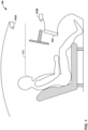
- FIG. 1 is a conceptual diagram illustrating an interior of a vehicle that includes an example vehicle computing system configured to determine driver engagement using three-dimensional (3D) eye gaze vectors, in accordance with one or more aspects of the present disclosure.
- FIG. 1 shows a cross-sectional view of an interior of vehicle 100 (also referred to herein as a "cabin" of vehicle 100) in addition to cameras 102A and 102B (collectively, “cameras 102"), and vehicle computing system 104.
- the vehicle illustrated in FIG. 1 may be an automobile, but aspects of the present disclosure may also be applicable to other types of vehicles, including trucks, motorcycles, aircraft, watercraft, trains, or other vehicles.
- a driver may normally occupy the seat and other passenger seats may be positioned behind or next to the seat.
- Cameras 102 may be one or more of any appropriate type of image acquisition device, such as a camera or charge-coupled device.
- cameras 102 may be one or more infrared cameras with a high field-of-view and shallow depth of focus, and may be a backlit infrared camera oriented to point generally towards one or more seats of vehicle 100.
- cameras 102 may be or may further include one or more other types of cameras or image sensors, which may include one or more other infrared cameras, thermographic cameras, thermal imaging cameras, light-sensitive cameras, range sensors, depth cameras, tomography devices, radar devices, or ultrasonic cameras.
- cameras 102 may be any image capture device appropriate for application of computer vision techniques.
- vehicle computing system 104 may operate to assist, inform, entertain, or perform other tasks that require user interactions with occupants of a vehicle.
- Vehicle computing system 104 may be referred to as a vehicle head unit, an infotainment system, or a subcomponent thereof.
- vehicle computing system 104 may execute various applications that perform functions or process information, on behalf of one or more occupants of the vehicle.
- vehicle computing system 104 may provide a navigation service that provides directions to destinations.
- Vehicle computing system 104 may also provide an information retrieval service that provides information in response to queries and/or as preemptive assistance or recommendations.
- Vehicle computing system 104 may also provide vehicle data about the vehicle, or multimedia such as audio or video.
- vehicle computing system 104 may provide many additional capabilities. In this and other ways, vehicle computing system 104 may improve the driving or riding experience for one or more occupants of the vehicle.
- the camera system and/or vehicle computing system 104 may determine a location of an occupant within the interior of vehicle 100 and may determine a 3D eye gaze vector of the occupant (e.g., 3D eye gaze vector 112).
- Cameras 102 may capture images of an occupant of vehicle 100 as the occupant is driving vehicle 100 (e.g., the driver of vehicle 100). In some instances, cameras 102 may include cameras that capture images of other occupants of vehicle 100.
- Cameras 102 may be part of a camera system that includes at least one or more processors and a memory. The images captured by cameras 102 may be analyzed by the camera system or vehicle computing system 104 or both. In various examples, techniques described herein relating to vehicle computing system 104 may also be performed by the computing system in whole or in part.
- vehicle computing system 104 determines a distance from one or more of cameras 102 to the occupant's eyes (or head) using the images captured by one or more of cameras 102.
- at least two of cameras 102 capture an image of the occupant.
- Vehicle computing system 104 may analyze the parallax angles between the images given that the location of each of the at least two cameras 102 is known. Using the parallax angles and the distance between the cameras, vehicle computing system 104 determines the distance between one or more of the at least two cameras 102 and the occupant's eyes.
- one of cameras 102 may be an infrared camera. Using a single one of cameras 102, vehicle computing system 104 may analyze the distortion of the image captured by the infrared camera to determine the distance between the infrared camera 102 and the occupant's eyes.
- vehicle computing system 104 may place the occupant's eyes in 3D space relative to cameras 102. That is, vehicle computing system 104 and/or the camera system may determine a location of the occupant's eyes within the interior of vehicle 100 relative to one or more of cameras 102. The location of the occupant's eyes is a location within a 3D space defined relative to one or more of cameras 102. For example, the 3D space may be spherical and have a centroid that corresponds to a location of one of cameras 102.
- the location of the occupant's eyes may be defined in terms of (x,y,z) coordinates where (0,0,0) is the location of the one of camera 102 that is being used as the centroid of the sphere.
- Such a coordinate may be referred to as being located within a "camera-based coordinate system.”
- Vehicle computing system 104 may also track the eye of the occupant of vehicle 100. For example, using cameras 102, vehicle computing system 104 tracks the eye position and movement of the occupant across multiple different images captured by cameras 102. Using the eye position and movement of a pupil or other features of the eye (i.e. eye tracking), vehicle computing system 104 determines a first initial 3D eye gaze vector. However, in various instances, the occupant's eyes may be occluded and, thus, the images captured by cameras 102 may not include a clear image of the occupant's eyes. Thus, rather than just relying upon tracking the position and movement of the occupant's eyes, vehicle computing system 104 further analyzes the captured images to determine a facial plane of the occupant.
- vehicle computing system 104 In calculating the facial plane of the occupant, vehicle computing system 104 identifies a plurality of facial landmarks in one or more images captured by one or more of cameras 102. Facial landmarks may include edges of a mouth, eyes, nose, ears, eyebrows, jaw, or other facial features. Using the identified facial landmarks, vehicle computing system 104 determines if the occupant's face included in image exhibits any pitch, roll, or yaw based on a geometric consistency between the various facial landmarks. For example, if the distances between the occupant's two eyes relative to the overall distance between the occupant's mouth and eyes is smaller than when the occupant is looking straight ahead, vehicle computing system 104 determines that the occupant is looking to the left or right.
- vehicle computing system 104 determines that the occupant is looking to the left.
- the pitch, roll, and yaw angles of the facial plane may be determined based on the relative change in distances between facial landmarks.
- vehicle computing system 104 uses the pitch, roll, and yaw angles of the determined facial plane, vehicle computing system 104 determines a second initial 3D eye gaze vector.
- pitch, roll, and yaw may refer a rotation of a user's head about a particular axis.
- roll may refer to a head that is rotated about its vertical axis, which is also referred to as rotating the head from side to side.
- vehicle computing system 104 may apply a trained machine learning model to the image to determine the facial plane.
- the machine learning model may be trained using images of other people having the facial landmarks already identified and the facial plane angle already determined.
- the machine learning model may continually learn based on user feedback and feedback provided by vehicle computing system 104. For example, vehicle computing system 104 may rank or adjust the parameters of the machine learning model based on the first initial 3D eye gaze vector determined using eye tracking as compared to the second 3D eye gaze vector determined using the facial plane. Additional details of how the machine learning system may operate is described below with respect to FIGS. 6A-6E .
- vehicle computing system 104 determines based on both the first and second initial 3D eye gaze vectors, 3D eye gaze vector 112 of the occupant. In various instances, vehicle computing system 104 may determine 3D eye gaze vector 112 using an average of the first and second initial 3D eye gaze vectors. Vehicle computing system 104 applies a weighting to one or more of the first and second 3D eye gaze vectors and use the weighted values to determine 3D eye gaze vector 112. Vehicle computing system 104 may determine weights to apply to the first and second initial 3D eye gaze vectors based on a confidence that the first or second initial 3D eye gaze vector was accurately determined.
- vehicle computing system 104 may apply a reduced weighting value to the second initial 3D eye gaze vector and an increased weighting value to the first initial 3D eye gaze vector determined using eye tracking.
- vehicle computing system 104 may also determine 3D eye gaze vector 112 using one of the first and second initial 3D eye gaze vectors. For example, if the occupant's eyes are closed in the image captured by cameras 102 or the occupant is wearing sunglasses, vehicle computing system 104 may use the second initial 3D eye gaze vector (i.e., the 3D eye gaze vector determined based on the pitch, roll, and yaw of the facial plane of the occupant) as 3D eye gaze vector 112.
- the second initial 3D eye gaze vector i.e., the 3D eye gaze vector determined based on the pitch, roll, and yaw of the facial plane of the occupant
- vehicle computing system 104 may use the first initial 3D eye gaze vector (i.e., the 3D eye gaze vector determined using eye tracking) as 3D eye gaze vector 112.
- the camera system may determine 3D eye gaze vector 112. That is, rather than vehicle computing system 104 receiving one or more images from cameras 102, the camera system may analyze the images (e.g., within each of cameras 102 or using a computing device distinct from vehicle computing system 104), determine 3D eye gaze vector 112 and provide the values of 3D eye gaze vector 112 to vehicle computing system 104. In some instances, the camera system determines the first and second initial 3D eye gaze vectors and provide those to vehicle computing system 104. Vehicle computing system 104 may then determine 3D eye gaze vector 112 using the first and second initial 3D eye gaze vectors received from the camera system.
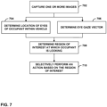
- Vehicle computing system 104 uses 3D eye gaze vector 112 and the location of the occupant's eyes relative to one or more of cameras 102, determines one or more regions of interest at which the occupant is looking. In order to make such a determination, vehicle computing system 104 determines where 3D eye gaze vector 112 intersects with one or more locations of the interior of vehicle 100. As one example, vehicle 100 may be different from a second example vehicle 100, vehicle computing system 104 is provided with a vehicle-specific data file.
- the vehicle data file includes a respective set of coordinates for each region of interest in the interior of vehicle 100, where each of the respective set of coordinates are defined relative to a centroid of the interior of the vehicle (i.e., using the vehicle-based coordinate system) and each of the respective coordinate sets define a two-dimensional plane for the region of interest. Further, by using vehicle data files that define interior features of various vehicles, techniques of this disclosure may be more easily applied across a wide variety of vehicles without requiring a programmer to customize the calculations for each different vehicle.
- vehicle computing system 104 may transform the initial location coordinates of the occupant's eyes to a set of coordinates defined relative to the centroid specified in the vehicle data file. That is, rather than using the coordinates for a sphere defined relative to one or more of cameras 102, vehicle computing system 104 adjusts the location of the occupant's eyes to define the location relative to a centroid of a sphere that encompasses the interior of vehicle 100.
- Coordinate locations within the sphere that encompasses the interior of vehicle 100 and has a centroid located somewhere other than a location of one of cameras 102 may be referred to herein as having coordinates within the "vehicle-based coordinate system.”
- the centroid of vehicle-based coordinate system may be located at a center point of the interior of vehicle 100. In other instances, the centroid may be located at a central point in space between the driver's seat and the dashboard or steering wheel of vehicle 100.
- the vehicle data file may define the location of one or more cameras 102 within vehicle 100 (e.g., in terms of (x,y,z) coordinates) using the vehicle-based coordinate system.
- Vehicle computing system 104 uses the coordinate location of the one or more cameras 102 and the coordinate location of the occupant's eyes defined using the camera-based coordinate system and generates a new coordinate location of the occupant's eyes in the vehicle-based coordinate system.
- vehicle computing system 104 uses the vehicle-based coordinate system location of the occupant's eyes to project 3D eye gaze vector 112 out from the occupant's eyes until it intersects with a plane associated with a region of interest. Vehicle computing system 104 determines that the plane that is intersected by 3D eye gaze vector 112 is the region of interest at which the occupant of vehicle 100 is looking. As shown in FIG. 1 , 3D eye gaze 112 is projected out towards the windshield of vehicle 100. Thus, vehicle computing system 104 may determine that the occupant is looking out the windshield of vehicle 100 and is engaged with driving vehicle 100.
- vehicle computing system 104 may periodically or continually determine at which region of interest the occupant of vehicle 100 is looking over time. By monitoring which regions of interest the occupant is looking at, vehicle computing system 104 may determine a level of engagement of the occupant and may determine how well the occupant is following the rules of the road and safe driving best practices. For example, if the occupant changes lanes without looking at a sideview mirror or reverses vehicle 100 without looking out the rear window, vehicle computing system 104 may determine that the occupant is not driving vehicle 100 in accordance with safety best practices. As another example, if the occupant is looking at a display of vehicle computing system 104 for a prolonged period of time while vehicle 100 is in motion, vehicle computing system 104 may lock out or other prohibit the occupant from interacting with vehicle computing system 104.
- techniques of this disclosure may enable a vehicle computing system to more accurately determine where an occupant of a vehicle is looking and, in instances where the occupant is the driver of the vehicle, more accurately determine driver engagement. Further, vehicle computing system 104 may use the more accurate determination of what the occupant is looking at to automatically take various safety-related actions or any number of other actions. Accordingly, techniques of this disclosure may enable improved vehicle safety systems.
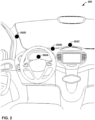
- FIG. 2 is a conceptual diagram illustrating an example vehicle having an interior camera system, in accordance with one or more aspects of the present disclosure.
- Vehicle interior 200 as shown in FIG. 2 , includes four cameras 202A-202D (collectively, "cameras 202") placed at various different locations of vehicle interior 200.
- Each of cameras 202 may be an example of cameras 102 shown and described with respect to FIG. 1 .
- camera 202D located within the A-pillar on the driver's side, may be an infrared camera that captures images used to determine a distance from camera 202D to the driver's eyes.
- vehicle computing system 104 may use images captured by both camera 202B and 202D to determine the parallax angle relative to the driver's eyes and, using the parallax angle, determine the distance from one or both of cameras 202B and 202D (or a central point between cameras 202B and 202D) to the driver's eyes.
- vehicle interior 200 is of a lefthand drive vehicle
- vehicle interior 200 or vehicle 100 of FIG. 1 may be a right-hand drive vehicle.
- placement of cameras 202 may be flipped (e.g., camera 202D may be on the right side A pillar).
- FIG. 3 is a conceptual diagram illustrating an example facial plane of a driver, in accordance with one or more aspects of the present disclosure.
- vehicle computing system 104 identified one or more facial landmarks 302 and facial plane 304, and determined 3D eye gaze vector 306.
- Facial landmark 302 include two corners of the driver's mouth, the base of the driver's nose, and the corner of each of the driver's eyes.
- Vehicle computing system 104 may define the facial plane using these facial landmarks 302. For example, vehicle computing system 104 may determine the distances between one or more facial landmarks 302. In some instances, vehicle computing system 104 may determine the distance between the two corners of the driver's mouth and/or between corners of different eyes. By comparing these distances to reference or learned distances for the driver, vehicle computing system 104 may determine coordinates that define facial plane 304.
- vehicle computing system 104 may use the region of interest at which the driver is looking to differentiate between actions being performed by the driver and actions being performed by a passenger. For example, if vehicle computing system 104 is receiving user input from a user interacting with the infotainment system (e.g., entering an address in a navigation application, selecting music, adjusting vehicle or passenger settings, etc.), vehicle computing system 104 determines whether the driver is looking at region of interest 400F. If vehicle computing system 104 determines that the driver is not looking at region of interest 400F, vehicle computing system 104 may determine that a passenger is providing the inputs and allow the passenger to continue to use the infotainment system without restriction.
- infotainment system e.g., entering an address in a navigation application, selecting music, adjusting vehicle or passenger settings, etc.
- presence-sensitive input component 504 may detect an object two inches or less from presence-sensitive input component 504 and other ranges are also possible. Presence-sensitive input component 504 may determine the location of presence-sensitive input component 504 selected by a user's finger using capacitive, inductive, and/or optical recognition techniques.
- presence-sensitive display 512 may also provide output to a user using tactile, audio, or video stimuli as described with respect to output component 546.
- presence-sensitive display 512 may include display component 502 that displays a graphical user interface.
- Display component 502 may be any type of output component that provides visual output, such as described with respect to output components 546.
- presence-sensitive display 512 may, in some examples, be an external component that shares a data or information path with other components of computing device 500 for transmitting and/or receiving input and output.
- presence-sensitive display 512 may be a built-in component of computing device 500 located within and physically connected to the external packaging of computing device 500 (e.g., an in-vehicle screen mounted in a dashboard of a vehicle).
- presence-sensitive display 512 may be an external component of computing device 500 located outside and physically separated from the packaging of computing device 500 (e.g., a monitor, a projector, etc. that shares a wired and/or wireless data path with a electronic control unit of the vehicle).
- presence-sensitive display 512 when located outside of and physically separated from the packaging of computing device 500, may be implemented by two separate components: a presence-sensitive input component 504 for receiving input and a display component 502 for providing output.
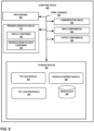
- One or more storage components 548 within computing device 500 may store information for processing during operation of computing device 500 (e.g., computing device 500 may store data accessed by modules 522, 524, and 526 during execution at computing device 500).
- storage component 548 is a temporary memory, meaning that a primary purpose of storage component 548 is not long-term storage.
- Storage components 548 on computing device 500 may be configured for short-term storage of information as volatile memory and therefore not retain stored contents if powered off. Examples of volatile memories include random access memories (RAM), dynamic random access memories (DRAM), static random access memories (SRAM), and other forms of volatile memories known in the art.
- processors 540 may implement functionality and/or execute instructions associated with computing device 500. Examples of processors 540 include application processors, display controllers, auxiliary processors, one or more sensor hubs, and any other hardware configure to function as a processor, a processing unit, or a processing device. Modules 522, 524, and 526 may be operable by processors 540 to perform various actions, operations, or functions of computing device 500. For example, processors 540 of computing device 500 may retrieve and execute instructions stored by storage components 548 that cause processors 540 to perform the operations described herein that are attributed to modules 522, 524, and 526. The instructions, when executed by processors 540, may cause computing device 500 to store information within storage components 548.
- Eye location module 524 may analyze parallax angles between images captured by two or more different cameras given that the location of each of the two or more cameras is known. Using the parallax angles and the distance between the cameras, eye location module 524 determines the distance between one or more of the two or more cameras and the occupant's eyes. As another example, eye location module 524 may analyze an image captured by a single infrared camera to determine the distortion of the image captured by the infrared camera to determine the distance between the infrared camera and the occupant's eyes.
- eye location module 524 may place the occupant's eyes in 3D space relative to the two or more cameras. That is, eye location module 524 may determine a location of the occupant's eyes within the interior of a vehicle relative to a location of at least one camera. The location of the occupant's eyes is a location within a 3D space defined relative to the at least one camera. For example, the 3D space may be spherical and have a centroid that corresponds to a location of a camera.
- Eye gaze module 522 may determine the 3D eye gaze vector of an occupant of a vehicle consistent with the techniques described with respect to FIGS. 1 and 3 . While shown as being a component of computing device 500, in various examples, the functionality of eye gaze module 522 may be performed by a camera system of the vehicle instead of or in additional to being performed by computing device 500. Further, the camera system and eye gaze module 522 may perform discrete portions of the 3D eye gaze vector determination process.
- eye gaze module 522 may perform eye tracking to determine a first initial 3D eye gaze vector and may determine a facial plane of the occupant to determine a second initial 3D eye gaze vector. Eye gaze module 522 may combine the first and second initial 3D eye gaze vectors to determine a final 3D eye gaze vector for the occupant. Using the eye position and movement of a pupil or other features of the eye (i.e. eye tracking), eye gaze module 522 may determine a first initial 3D eye gaze vector. However, in various instances, the occupant's eyes may be occluded and, thus, the images captured by the cameras may not include a clear image of the occupant's eyes. Thus, rather than just relying upon tracking the position and movement of the occupant's eyes, eye gaze module 522 may further analyze the captured images to determine a facial plane of the occupant.
- eye gaze module 522 may identify a plurality of facial landmarks in one or more images captured by one or more of cameras 102. Facial landmarks may include edges of a mouth, eyes, nose, ears, eyebrows, jaw, or other facial features. Using the identified facial landmarks, eye gaze module 522 may determine if the occupant's face included in image exhibits any pitch, roll, or yaw based on a geometric consistency between the various facial landmarks. For example, if the distances between the occupant's two eyes relative to the overall distance between the occupant's mouth and eyes is smaller than when the occupant is looking straight ahead, eye gaze module 522 determines that the occupant is looking to the left or right.
- eye gaze module 522 determines that the occupant is looking to the left.
- the pitch, roll, and yaw angles of the facial plane may be determined based on the relative change in distances between facial landmarks. Using the pitch, roll, and yaw angles of the determined facial plane, eye gaze module 522 may determine a second initial 3D eye gaze vector.
- eye gaze module 522 may apply a trained machine learning model to the image to determine the facial plane.
- the machine learning model may be trained using images of other people having the facial landmarks already identified and the facial plane angle already determined.
- the machine learning model may continually learn based on user feedback and feedback provided by eye gaze module 522. For example, eye gaze module 522 may rank or adjust the parameters of the machine learning model based on the first initial 3D eye gaze vector determined using eye tracking as compared to the second 3D eye gaze vector determined using the facial plane.
- eye gaze module 522 may determine, based on both the first and second initial 3D eye gaze vectors, a 3D eye gaze vector of the occupant. In various instances, eye gaze module 522 may determine the 3D eye gaze vector using an average of the first and second initial 3D eye gaze vectors. Eye gaze module 522 may, in other examples, apply a weighting to one or more of the first and second 3D eye gaze vectors and use the weighted values to the determine 3D eye gaze vector. Eye gaze module 522 may determine weights to apply to the first and second initial 3D eye gaze vectors based on a confidence that the first or second initial 3D eye gaze vector was accurately determined.
- eye gaze module 522 may apply a reduced weighting value to the second initial 3D eye gaze vector and an increased weighting value to the first initial 3D eye gaze vector determined using eye tracking.
- eye gaze module 522 may also determine a 3D eye gaze vector using one of the first and second initial 3D eye gaze vectors. For example, if the occupant's eyes are closed in the images captured by the two or more cameras or the occupant is wearing sunglasses, eye gaze module 522 may use the second initial 3D eye gaze vector (i.e., the 3D eye gaze vector determined based on the pitch, roll, and yaw of the facial plane of the occupant) as the determined 3D eye gaze vector.
- the second initial 3D eye gaze vector i.e., the 3D eye gaze vector determined based on the pitch, roll, and yaw of the facial plane of the occupant
- eye gaze module 522 may use the first initial 3D eye gaze vector (i.e., the 3D eye gaze vector determined using eye tracking) as the determined 3D eye gaze vector.
- Region of interest module 526 may determine which region of interest at which an occupant of the vehicle is looking, consistent with the techniques described with respect to FIGS. 1 and 4 .
- Region of interest module 526 may load vehicle specific data from vehicle data 528.
- Vehicle data 528 may be any type of data store, such as a file, a database, or other data structure suitable for storing textual or encoded information usable by region of interest module to determine at which region of interest the occupant is looking.
- Vehicle data includes coordinates that define two-dimensional planes associate with various regions of interest of the vehicle.
- each plane may be associated with a different physical element of the vehicle (e.g., a rearview mirror, a head unit display, an instrument panel, etc.) or different portions of the same physical element of the vehicle (e.g., different areas of the windshield).
- a different physical element of the vehicle e.g., a rearview mirror, a head unit display, an instrument panel, etc.
- different portions of the same physical element of the vehicle e.g., different areas of the windshield.
- Region of interest module may receive the 3D eye gaze vector information from eye gaze module 522 and may also receive occupant head and/or eye location information from eye location module 524.
- Region of interest module 526 may transform the head and/or eye location information from the camera-based coordinate system to the vehicle-based coordinate system. By transforming the coordinates to the vehicle-based coordinate system, region of interest module 526 may locate the head and/or eyes of the occupant relative to the coordinate locations of various physical objects of the vehicle as specified in the vehicle data.
- Region of interest module 526 may project the 3D eye gaze vector from the vehicle-based coordinate system location of the occupant's head and/or eyes and determine one or more planes intersected by the 3D eye gaze vector. Region of interest module 526 identifies the intersected planes as the regions of interest at which the occupant is looking.
- region of interest module 526 may periodically or continually determine at which region of interest the occupant of the vehicle is looking over time. By monitoring which regions of interest the occupant is looking at, region of interest module 526 may determine a level of engagement of the occupant and may determine how well the occupant is following the rules of the road and safe driving best practices. For example, if the occupant changes lanes without looking at a sideview mirror or reverses vehicle without looking out the rear window, computing device 500 may determine that the occupant is not driving the vehicle in accordance with safety best practices. As another example, if the occupant is looking at a display of computing device 500 for a prolonged period of time while the vehicle is in motion, computing device 500 may lock out or other prohibit the occupant from interacting with computing device 500.
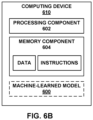
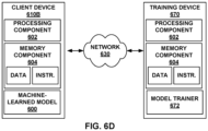
- computing device 500 may include one or more trained machine learning modules that are applied to the images captures by the cameras.
- machine-learned model 600 can perform various types of classification based on the input data.
- machine-learned model 600 can perform binary classification or multiclass classification.
- binary classification the output data can include a classification of the input data into one of two different classes.
- multiclass classification the output data can include a classification of the input data into one (or more) of more than two classes.
- the classifications can be single label or multi-label.
- Machine-learned model 600 may perform discrete categorical classification in which the input data is simply classified into one or more classes or categories.
- machine-learned model 600 can be a parametric model while, in other implementations, machine-learned model 600 can be a non-parametric model. In some implementations, machine-learned model 600 can be a linear model while, in other implementations, machine-learned model 600 can be a non-linear model.
- machine-learned model 600 can be or include one or more of various different types of machine-learned models. Examples of such different types of machine-learned models are provided below for illustration. One or more of the example models described below can be used (e.g., combined) to provide the output data in response to the input data. Additional models beyond the example models provided below can be used as well.
- machine-learned model 600 can be or include one or more classifier models such as, for example, linear classification models; quadratic classification models; etc.
- Machine-learned model 600 may be or include one or more regression models such as, for example, simple linear regression models; multiple linear regression models; logistic regression models; stepwise regression models; multivariate adaptive regression splines; locally estimated scatterplot smoothing models; etc.
- Machine-learned model 600 can be or include one or more Bayesian models such as, for example, naive Bayes models; Gaussian naive Bayes models; multinomial naive Bayes models; averaged one-dependence estimators; Bayesian networks; Bayesian belief networks; hidden Markov models; etc.
- Bayesian models such as, for example, naive Bayes models; Gaussian naive Bayes models; multinomial naive Bayes models; averaged one-dependence estimators; Bayesian networks; Bayesian belief networks; hidden Markov models; etc.
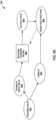
- machine-learned model 600 can be or include one or more artificial neural networks (also referred to simply as neural networks).
- a neural network can include a group of connected nodes, which also can be referred to as neurons or perceptrons.
- a neural network can be organized into one or more layers. Neural networks that include multiple layers can be referred to as "deep" networks.
- a deep network can include an input layer, an output layer, and one or more hidden layers positioned between the input layer and the output layer. The nodes of the neural network can be connected or non-fully connected.
- Example recurrent neural networks include long short-term (LSTM) recurrent neural networks; gated recurrent units; bi-direction recurrent neural networks; continuous time recurrent neural networks; neural history compressors; echo state networks; Elman networks; Jordan networks; recursive neural networks; Hopfield networks; fully recurrent networks; sequence-to- sequence configurations; etc.
- LSTM long short-term
- machine-learned model 600 can be or include one or more convolutional neural networks.
- a convolutional neural network can include one or more convolutional layers that perform convolutions over input data using learned filters.
- Filters can also be referred to as kernels.
- Convolutional neural networks can be especially useful for vision problems such as when the input data includes imagery such as still images or video. However, convolutional neural networks can also be applied for natural language processing.
- machine-learned model 600 can be or include one or more generative networks such as, for example, generative adversarial networks.
- Generative networks can be used to generate new data such as new images or other content.
- Machine-learned model 600 may be or include an autoencoder.
- the aim of an autoencoder is to learn a representation (e.g., a lower- dimensional encoding) for a set of data, typically for the purpose of dimensionality reduction.
- an autoencoder can seek to encode the input data and the provide output data that reconstructs the input data from the encoding.
- the autoencoder concept has become more widely used for learning generative models of data.
- the autoencoder can include additional losses beyond reconstructing the input data.
- Machine-learned model 600 may be or include one or more other forms of artificial neural networks such as, for example, deep Boltzmann machines; deep belief networks; stacked autoencoders; etc. Any of the neural networks described herein can be combined (e.g., stacked) to form more complex networks.
- One or more neural networks can be used to provide an embedding based on the input data.
- the embedding can be a representation of knowledge abstracted from the input data into one or more learned dimensions.
- embeddings can be a useful source for identifying related entities.
- embeddings can be extracted from the output of the network, while in other instances embeddings can be extracted from any hidden node or layer of the network (e.g., a close to final but not final layer of the network).
- Embeddings can be useful for performing auto suggest next video, product suggestion, entity or object recognition, etc.
- embeddings be useful inputs for downstream models. For example, embeddings can be useful to generalize input data (e.g., search queries) for a downstream model or processing system.
- Machine-learned model 600 may include one or more clustering models such as, for example, k-means clustering models; k-medians clustering models; expectation maximization models; hierarchical clustering models; etc.
- clustering models such as, for example, k-means clustering models; k-medians clustering models; expectation maximization models; hierarchical clustering models; etc.
- machine-learned model 600 can perform one or more dimensionality reduction techniques such as, for example, principal component analysis; kernel principal component analysis; graph-based kernel principal component analysis; principal component regression; partial least squares regression; Sammon mapping; multidimensional scaling; projection pursuit; linear discriminant analysis; mixture discriminant analysis; quadratic discriminant analysis; generalized discriminant analysis; flexible discriminant analysis; autoencoding; etc.
- principal component analysis kernel principal component analysis
- graph-based kernel principal component analysis principal component regression
- partial least squares regression Sammon mapping
- multidimensional scaling projection pursuit
- linear discriminant analysis mixture discriminant analysis
- quadratic discriminant analysis generalized discriminant analysis
- flexible discriminant analysis flexible discriminant analysis
- autoencoding etc.
- machine-learned model 600 can perform or be subjected to one or more reinforcement learning techniques such as Markov decision processes; dynamic programming; Q functions or Q-learning; value function approaches; deep Q-networks; differentiable neural computers; asynchronous advantage actor-critics; deterministic policy gradient; etc.
- reinforcement learning techniques such as Markov decision processes; dynamic programming; Q functions or Q-learning; value function approaches; deep Q-networks; differentiable neural computers; asynchronous advantage actor-critics; deterministic policy gradient; etc.
- machine-learned model 600 can be an autoregressive model.
- an autoregressive model can specify that the output data depends linearly on its own previous values and on a stochastic term.
- an autoregressive model can take the form of a stochastic difference equation.
- WaveNet is a generative model for raw audio.
- machine-learned model 600 can include or form part of a multiple model ensemble.
- bootstrap aggregating can be performed, which can also be referred to as "bagging."
- a training dataset is split into a number of subsets (e.g., through random sampling with replacement) and a plurality of models are respectively trained on the number of subsets.
- respective outputs of the plurality of models can be combined (e.g., through averaging, voting, or other techniques) and used as the output of the ensemble.
- Random forests are an ensemble learning method for classification, regression, and other tasks. Random forests are generated by producing a plurality of decision trees at training time. In some instances, at inference time, the class that is the mode of the classes (classification) or the mean prediction (regression) of the individual trees can be used as the output of the forest. Random decision forests can correct for decision trees' tendency to overfit their training set.
- Stacking includes training a combiner model to blend or otherwise combine the predictions of several other machine-learned models.
- a plurality of machine-learned models e.g., of same or different type
- a combiner model can be trained to take the predictions from the other machine-learned models as inputs and, in response, produce a final inference or prediction.
- a single-layer logistic regression model can be used as the combiner model.
- Boosting can include incrementally building an ensemble by iteratively training weak models and then adding to a final strong model. For example, in some instances, each new model can be trained to emphasize the training examples that previous models misinterpreted (e.g., misclassified). For example, a weight associated with each of such misinterpreted examples can be increased.
- AdaBoost AdaBoost
- Other example boosting techniques include LPBoost; TotalBoost; BrownBoost; xgboost; MadaBoost, LogitBoost, gradient boosting; etc.
- any of the models described above e.g., regression models and artificial neural networks
- an ensemble can include a top level machine-learned model or a heuristic function to combine and/or weight the outputs of the models that form the ensemble.
- machine-learned model 600 can be used to preprocess the input data for subsequent input into another model.
- machine-learned model 600 can perform dimensionality reduction techniques and embeddings (e.g., matrix factorization, principal components analysis, singular value decomposition, word2vec/GLOVE, and/or related approaches); clustering; and even classification and regression for downstream consumption. Many of these techniques have been discussed above and will be further discussed below.
- machine-learned model 600 can receive and use the input data in its raw form.
- the raw input data can be preprocessed.
- machine-learned model 600 can receive and use the preprocessed input data.
- backward propagation of errors can be used in conjunction with an optimization technique (e.g., gradient based techniques) to train machine-learned model 300 (e.g., when machine-learned model is a multi-layer model such as an artificial neural network).
- an iterative cycle of propagation and model parameter (e.g., weights) update can be performed to train machine-learned model 600.
- Example backpropagation techniques include truncated backpropagation through time, Levenberg-Marquardt backpropagation, etc.
- one or more generalization techniques can be performed during training to improve the generalization of machine-learned model 600.
- Generalization techniques can help reduce overfitting of machine-learned model 600 to the training data.
- Example generalization techniques include dropout techniques; weight decay techniques; batch normalization; early stopping; subset selection; stepwise selection; etc.
- various techniques can be used to optimize and/or adapt the learning rate when the model is trained.
- Example techniques and/or tools for performing learning rate optimization or adaptation include Adagrad; Adaptive Moment Estimation (ADAM); Adadelta; RMSprop; etc.
- transfer learning techniques can be used to provide an initial model from which to begin training of machine-learned model 600 described herein.
- machine-learned model 600 described herein can be included in different portions of computer-readable code on a computing device.
- machine-learned model 600 can be included in a particular application or program and used (e.g., exclusively) by such particular application or program.
- a computing device can include a number of applications and one or more of such applications can contain its own respective machine learning library and machine-learned model(s).
- machine-learned model 600 described herein can be included in an operating system of a computing device (e.g., in a central intelligence layer of an operating system) and can be called or otherwise used by one or more applications that interact with the operating system.
- each application can communicate with the central intelligence layer (and model(s) stored therein) using an application programming interface (API) (e.g., a common, public API across all applications).
- API application programming interface
- Databases and applications can be implemented on a single system or distributed across multiple systems. Distributed components can operate sequentially or in parallel.
- machine learning techniques described herein are readily interchangeable and combinable. Although certain example techniques have been described, many others exist and can be used in conjunction with aspects of the present disclosure.
Landscapes
- Engineering & Computer Science (AREA)
- Theoretical Computer Science (AREA)
- Physics & Mathematics (AREA)
- General Physics & Mathematics (AREA)
- Multimedia (AREA)
- Health & Medical Sciences (AREA)
- General Health & Medical Sciences (AREA)
- Human Computer Interaction (AREA)
- Oral & Maxillofacial Surgery (AREA)
- Computer Vision & Pattern Recognition (AREA)
- Automation & Control Theory (AREA)
- Software Systems (AREA)
- Mechanical Engineering (AREA)
- Transportation (AREA)
- Mathematical Physics (AREA)
- Ophthalmology & Optometry (AREA)
- Data Mining & Analysis (AREA)
- Signal Processing (AREA)
- Evolutionary Computation (AREA)
- Medical Informatics (AREA)
- Artificial Intelligence (AREA)
- Computing Systems (AREA)
- General Engineering & Computer Science (AREA)
- Traffic Control Systems (AREA)
- Image Analysis (AREA)
- Fittings On The Vehicle Exterior For Carrying Loads, And Devices For Holding Or Mounting Articles (AREA)
- User Interface Of Digital Computer (AREA)
- Control Of Driving Devices And Active Controlling Of Vehicle (AREA)
Claims (11)
- Computerimplementiertes Verfahren, umfassend:Erlangen, über ein Kamerasystem eines Fahrzeugs, mindestens eines Bildes eines Fahrers des Fahrzeugs;Bestimmen eines Standorts eines oder mehrerer Augen des Fahrers innerhalb des Fahrzeugs basierend auf dem mindestens einen Bild des Fahrers;Bestimmen eines Blickvektors basierend auf dem mindestens einen Bild des Fahrers, wobei das Bestimmen des Blickvektors Folgendes umfasst:Bestimmen eines ersten initialen 3D-Blickvektors basierend auf dem Bild und unter Verwendung von Augenverfolgung;Identifizieren eines oder mehrerer Gesichtsmerkmale in dem mindestens einen Bild;Bestimmen eines Steigungswinkels, eines Rollwinkels und eines Gierwinkels einer Gesichtsebene des Fahrers basierend auf dem einen oder den mehreren Gesichtsmerkmalen;Bestimmen eines zweiten initialen 3D-Blickvektors basierend auf dem Steigungswinkel, dem Rollwinkel und dem Gierwinkel; undBestimmen des Blickvektors durch Gewichten des ersten initialen 3D-Blickvektors und des zweiten initialen 3D-Blickvektors;Bestimmen der Position des einen oder der mehreren Augen des Fahrers basierend auf dem Blickvektor und einer Fahrzeugdatendatei des Fahrzeugs, eines Interessenbereichs im Innenraum des Fahrzeugs aus einer Vielzahl von Interessenbereichen im Innenraum des Fahrzeugs, wobei die Fahrzeugdatendatei jeweilige Positionen jedes der Vielzahl von Interessenbereichen im Innenraum des Fahrzeugs spezifiziert und wobei der Interessenbereich einer Fahrzeugkopfeinheit entspricht; undselektives Durchführen einer Aktion, umfassend Ausgeben einer Nachricht, die den Fahrer daran erinnert, auf die Straße zu achten, basierend auf einer Bestimmung, dass der Fahrer mehr als eine Schwellenanzahl von Benutzereingaben an die Fahrzeugkopfeinheit innerhalb einer ersten vorbestimmten Zeitspanne bereitgestellt hat oder mit der Fahrzeugkopfeinheit für länger als eine zweite vorbestimmte Zeitspanne interagiert hat.
- Verfahren nach Anspruch 1, wobei das Bestimmen des Blickvektors Folgendes umfasst:Bestimmen eines Winkels mindestens einer Pupille des Fahrers basierend auf dem mindestens einen Bild; undBestimmen des Blickvektors basierend auf dem Winkel der mindestens einen Pupille.
- Verfahren nach Anspruch 1 oder Anspruch 2, wobei das Bestimmen des Blickvektors Folgendes umfasst:
Anwenden mindestens eines Maschinenlernmodells auf das mindestens eine Bild, wobei das Maschinenlernmodell den Blickvektor ausgibt. - Verfahren nach einem der Ansprüche 1-3, wobei das mindestens eine Bild mindestens ein jeweiliges Bild umfasst, das durch jede von zwei oder mehr unterschiedlichen Kameras des Kamerasystems erfasst wird, und wobei das Bestimmen der Position des einen oder der mehreren Augen des Fahrers innerhalb des Fahrzeugs Folgendes umfasst:Bestimmen eines Parallaxenwinkels basierend auf dem mindestens einen jeweiligen Bild, das von jeder der zwei oder mehr unterschiedlichen Kameras erfasst wird;Bestimmen einer Entfernung von mindestens einer der zwei oder mehr unterschiedlichen Kameras zu dem einen oder den mehreren Augen des Fahrers, basierend auf den jeweiligen Positionen jeder der zwei oder mehr unterschiedlichen Kameras und dem Parallaxenwinkel; undBestimmen der Position des einen oder der mehreren Augen des Fahrers basierend auf der Entfernung und den jeweiligen Positionen jeder der zwei oder mehr unterschiedlichen Kameras.
- Verfahren nach einem der Ansprüche 1-3, wobei das mindestens eine Bild ein Bild umfasst, das unter Verwendung einer Infrarotkamera des Kamerasystems erfasst wird, und wobei das Bestimmen der Position des einen oder der mehreren Augen des Fahrers innerhalb des Fahrzeugs Folgendes umfasst:Bestimmen einer Entfernung von der Infrarotkamera zu dem einen oder den mehreren Augen des Fahrers basierend auf einer Verzerrung des Bildes; undBestimmen des Standorts des einen oder der mehreren Augen des Fahrers basierend auf dem Standort der Infrarotkamera und der Entfernung.
- Verfahren nach einem der Ansprüche 1-5,wobei der Standort des einen oder der mehreren Augen des Fahrers innerhalb des Fahrzeugs unter Verwendung eines kamerabasierten Koordinatensystems spezifiziert wird, das eine Kamera des Kamerasystems als Schwerpunkt aufweist,wobei die jeweiligen Positionen jedes der Vielzahl von Interessenbereichen unter Verwendung eines fahrzeugbasierten Koordinatensystems spezifiziert werden, das einen Schwerpunkt aufweist, der sich an einer Innenseite des Fahrzeugs befindet und sich von der Position der einen Kamera unterscheidet, und wobei das Bestimmen des Interessenbereichs, auf den der Fahrer schaut, Folgendes umfasst:Transformieren des Standorts des einen oder der mehreren Augen aus dem kamerabasierten Koordinatensystem in das fahrzeugbasierte Koordinatensystem;Bestimmen, ob sich ein Vorsprung des Blickvektors von dem Standort des einen oder der mehreren Augen, die unter Verwendung des fahrzeugbasierten Koordinatensystems spezifiziert werden, mit einem der Vielzahl von interessierenden Bereichen schneidet; undals Reaktion auf das Bestimmen, dass sich der Blickvektor mit einen bestimmten Interessenbereich aus der Vielzahl von Interessenbereichen schneidet, Bestimmen, dass der bestimmte Interessenbereich der Interessenbereich ist, auf den der Fahrer schaut.
- Verfahren nach einem der Ansprüche 1-6, wobei die Fahrzeugdatendatei Daten beinhaltet, die gemäß einer erweiterbaren Auszeichnungssprache strukturiert sind, wobei die Fahrzeugdatendatei einen jeweiligen Satz von Koordinaten für jeden interessierenden Bereich aus der Vielzahl von interessierenden Bereichen beinhaltet, wobei jeder der jeweiligen Koordinatensätze relativ zu einem Schwerpunkt einer Kugel definiert ist, die den Innenraum des Fahrzeugs umgibt, und wobei jeder der jeweiligen Sätze von Koordinaten eine zweidimensionale Ebene definiert.
- Rechenvorrichtung, umfassend:mindestens einen Prozessor; undSpeicher, umfassend Anweisungen, die, wenn sie durch den mindestens einen Prozessor ausgeführt werden, den mindestens einen Prozessor veranlassen, das Verfahren nach einem der Ansprüche 1-7 durchzuführen.
- Rechensystem, umfassend Mittel zum Durchführen des Verfahrens nach einem der Ansprüche 1-7.
- Computerlesbares Speichermedium, umfassend Anweisungen, die, wenn sie durch mindestens einen Prozessor einer Rechenvorrichtung ausgeführt werden, den mindestens einen Prozessor veranlassen, das Verfahren nach einem der Ansprüche 1-7 durchzuführen.
- Fahrzeug, umfassend die Rechenvorrichtung nach Anspruch 8.
Applications Claiming Priority (2)
| Application Number | Priority Date | Filing Date | Title |
|---|---|---|---|
| US201962862561P | 2019-06-17 | 2019-06-17 | |
| PCT/US2019/061025 WO2020256764A1 (en) | 2019-06-17 | 2019-11-12 | Vehicle occupant engagement using three-dimensional eye gaze vectors |
Publications (2)
| Publication Number | Publication Date |
|---|---|
| EP3776347A1 EP3776347A1 (de) | 2021-02-17 |
| EP3776347B1 true EP3776347B1 (de) | 2025-07-02 |
Family
ID=69165553
Family Applications (1)
| Application Number | Title | Priority Date | Filing Date |
|---|---|---|---|
| EP19836702.1A Active EP3776347B1 (de) | 2019-06-17 | 2019-11-12 | Fahrzeuginsasseneinrastung mit dreidimensionalen blickvektoren |
Country Status (6)
| Country | Link |
|---|---|
| US (2) | US11527082B2 (de) |
| EP (1) | EP3776347B1 (de) |
| JP (2) | JP7402796B2 (de) |
| KR (1) | KR102385874B1 (de) |
| CN (1) | CN112424788B (de) |
| WO (1) | WO2020256764A1 (de) |
Families Citing this family (39)
| Publication number | Priority date | Publication date | Assignee | Title |
|---|---|---|---|---|
| EP3776347B1 (de) * | 2019-06-17 | 2025-07-02 | Google LLC | Fahrzeuginsasseneinrastung mit dreidimensionalen blickvektoren |
| CN110281950B (zh) * | 2019-07-08 | 2020-09-04 | 睿镞科技(北京)有限责任公司 | 基于三维声像传感器的载运工具控制与可视化环境体验 |
| US11574244B2 (en) * | 2019-09-12 | 2023-02-07 | International Business Machines Corporation | States simulator for reinforcement learning models |
| CN111176524B (zh) * | 2019-12-25 | 2021-05-28 | 歌尔股份有限公司 | 一种多屏显示系统及其鼠标切换控制方法 |
| US11790669B2 (en) * | 2020-04-27 | 2023-10-17 | Nvidia Corporation | Systems and methods for performing operations in a vehicle using gaze detection |
| US11381730B2 (en) * | 2020-06-25 | 2022-07-05 | Qualcomm Incorporated | Feature-based image autofocus |
| US11518392B1 (en) * | 2020-06-26 | 2022-12-06 | BlueOwl, LLC | Systems and methods for identifying distracted driving events using unsupervised clustering |
| CN116194964A (zh) * | 2020-08-03 | 2023-05-30 | 谷歌有限责任公司 | 用于训练机器学习视觉注意力模型的系统和方法 |
| US11908208B2 (en) * | 2020-10-20 | 2024-02-20 | Toyota Motor Engineering & Manufacturing North America, Inc. | Interface sharpness distraction mitigation method and system |
| EP3993410B1 (de) * | 2020-10-28 | 2024-11-27 | Ningbo Geely Automobile Research & Development Co., Ltd. | Kamerasystem und verfahren zur erzeugung einer augenkontaktbildansicht einer person |
| JP7466687B2 (ja) * | 2020-10-30 | 2024-04-12 | 京セラ株式会社 | 検出装置および画像表示システム |
| JP7710838B2 (ja) * | 2020-12-15 | 2025-07-22 | キヤノン株式会社 | 被検体動き測定装置、被検体動き測定方法、プログラム、撮像システム |
| CN115082978A (zh) * | 2021-03-10 | 2022-09-20 | 佳能株式会社 | 面部姿态的检测装置、方法、图像处理系统及存储介质 |
| EP4334884A4 (de) * | 2021-05-05 | 2024-08-21 | Seeing Machines Limited | Systeme und verfahren zur erkennung der verwendung einer mobilen vorrichtung durch einen fahrzeugfahrer |
| US11951833B1 (en) * | 2021-05-16 | 2024-04-09 | Ambarella International Lp | Infotainment system permission control while driving using in-cabin monitoring |
| US12087092B2 (en) * | 2021-06-04 | 2024-09-10 | Rockwell Collins, Inc. | Pilot safety system with context-sensitive scan pattern monitoring and alerting |
| CN113525402B (zh) * | 2021-07-20 | 2023-06-02 | 张鹏 | 高级辅助驾驶及无人驾驶视场智能响应方法及系统 |
| KR102644877B1 (ko) * | 2021-08-20 | 2024-03-08 | 주식회사 경신 | 차량 제어 장치 및 방법 |
| KR102597068B1 (ko) * | 2021-11-16 | 2023-10-31 | 전남대학교 산학협력단 | 인공 지능을 이용하여 운전자의 주시 상태를 판단하는 차량 장치 및 그 제어 방법 |
| US12153905B2 (en) * | 2021-11-22 | 2024-11-26 | Jpmorgan Chase Bank, N.A. | System and method for adding no-code machine learning and artificial intelligence capabilities to intelligence tools |
| JP7556344B2 (ja) * | 2021-11-22 | 2024-09-26 | トヨタ自動車株式会社 | 画像表示システム |
| EP4224288B1 (de) * | 2022-02-07 | 2025-12-17 | Robert Ohrenstein | Vorrichtung zur bestimmung der blickrichtung |
| JP7846547B2 (ja) * | 2022-03-22 | 2026-04-15 | 株式会社Subaru | 乗員状態監視装置 |
| US12307782B2 (en) * | 2022-03-29 | 2025-05-20 | Woven By Toyota, Inc. | Object information obtaining method and system for implementing |
| US12366458B2 (en) * | 2022-03-30 | 2025-07-22 | Panasonic Automotive Systems Co., Ltd. | Information presentation method, information presentation system, and computer-readable medium |
| JP7770253B2 (ja) * | 2022-05-30 | 2025-11-14 | 本田技研工業株式会社 | 視線推定装置、視線推定方法、およびプログラム |
| US20240005698A1 (en) * | 2022-06-29 | 2024-01-04 | Microsoft Technology Licensing, Llc | Accurate head pose and eye gaze signal analysis |
| US11862016B1 (en) * | 2022-07-19 | 2024-01-02 | Jiangsu University | Multi-intelligence federal reinforcement learning-based vehicle-road cooperative control system and method at complex intersection |
| CN115631517A (zh) * | 2022-08-15 | 2023-01-20 | 浙江极氪智能科技有限公司 | 图像处理方法、装置、设备及存储介质 |
| EP4390857A1 (de) * | 2022-12-22 | 2024-06-26 | Ningbo Geely Automobile Research & Development Co. Ltd. | Fahrzeugsystem und verfahren zur bestimmung von anomalien im inneren eines fahrzeugs |
| GB2626135A (en) * | 2023-01-10 | 2024-07-17 | Mercedes Benz Group Ag | Brightness control of infotainment system in vehicles using eye-gaze estimation |
| CN115797453B (zh) * | 2023-01-17 | 2023-06-16 | 西南科技大学 | 一种红外微弱目标的定位方法、定位装置及可读存储介质 |
| DE102023202806A1 (de) * | 2023-03-28 | 2024-10-02 | Continental Automotive Technologies GmbH | Verfahren zur bildverarbeitung für videokonferenzen |
| US20240391382A1 (en) * | 2023-05-24 | 2024-11-28 | Cerence Operating Company | Multi-Level Warning Based on Driver Gaze |
| TWI890116B (zh) * | 2023-08-18 | 2025-07-11 | 先進車系統股份有限公司 | 適用於載具之駕駛員的視聽覺專心度判斷方法、主機和駕駛員監控系統 |
| WO2025115065A1 (ja) * | 2023-11-27 | 2025-06-05 | 日産自動車株式会社 | 画像処理方法及び画像処理システム |
| US12552546B2 (en) | 2024-05-30 | 2026-02-17 | Honeywell International s.r.o | Gaze-assisted verification of pilot activities |
| WO2026011020A1 (en) * | 2024-07-03 | 2026-01-08 | The Penn State Research Foundation | System for visualizing gaze points on dynamic multi-window displays using eye-trackers |
| CN119515954B (zh) * | 2024-11-19 | 2026-01-09 | 中南大学 | 一种爆区岩石破碎体积确定方法及系统 |
Family Cites Families (20)
| Publication number | Priority date | Publication date | Assignee | Title |
|---|---|---|---|---|
| US6154559A (en) | 1998-10-01 | 2000-11-28 | Mitsubishi Electric Information Technology Center America, Inc. (Ita) | System for classifying an individual's gaze direction |
| US6989754B2 (en) * | 2003-06-02 | 2006-01-24 | Delphi Technologies, Inc. | Target awareness determination system and method |
| US7508979B2 (en) * | 2003-11-21 | 2009-03-24 | Siemens Corporate Research, Inc. | System and method for detecting an occupant and head pose using stereo detectors |
| JP2007265367A (ja) | 2006-03-30 | 2007-10-11 | Fujifilm Corp | 視線検出方法および装置ならびにプログラム |
| JP4811259B2 (ja) * | 2006-12-11 | 2011-11-09 | 日産自動車株式会社 | 視線方向推定装置及び視線方向推定方法 |
| JP4725595B2 (ja) * | 2008-04-24 | 2011-07-13 | ソニー株式会社 | 映像処理装置、映像処理方法、プログラム及び記録媒体 |
| JP5590684B2 (ja) * | 2009-12-10 | 2014-09-17 | パナソニック株式会社 | 情報表示装置及び情報表示方法 |
| US8408706B2 (en) * | 2010-12-13 | 2013-04-02 | Microsoft Corporation | 3D gaze tracker |
| US9405982B2 (en) * | 2013-01-18 | 2016-08-02 | GM Global Technology Operations LLC | Driver gaze detection system |
| US9625723B2 (en) * | 2013-06-25 | 2017-04-18 | Microsoft Technology Licensing, Llc | Eye-tracking system using a freeform prism |
| DE102014109079A1 (de) * | 2013-06-28 | 2014-12-31 | Harman International Industries, Inc. | Vorrichtung und verfahren zur erfassung des interesses eines fahrers an einer werbeanzeige durch die verfolgung der blickrichtung des fahrers |
| GB2525656B (en) | 2014-05-01 | 2018-01-31 | Jaguar Land Rover Ltd | Control apparatus and related methods for addressing driver distraction |
| KR101795264B1 (ko) * | 2016-05-31 | 2017-12-01 | 현대자동차주식회사 | 얼굴 랜드마크 검출 장치 및 그 검증 방법 |
| US20170353714A1 (en) * | 2016-06-06 | 2017-12-07 | Navid Poulad | Self-calibrating display system |
| US10049571B2 (en) * | 2016-06-29 | 2018-08-14 | Toyota Jidosha Kabushiki Kaisha | Situational understanding of unknown roadway conditions that are ahead for a connected vehicle |
| KR101914362B1 (ko) * | 2017-03-02 | 2019-01-14 | 경북대학교 산학협력단 | 차량 내/외부 정보 통합 분석 기반의 위험 상황 경고 시스템 및 그 방법 |
| CN108334810B (zh) * | 2017-12-25 | 2020-12-11 | 北京七鑫易维信息技术有限公司 | 视线追踪设备中确定参数的方法和装置 |
| CN109493305A (zh) * | 2018-08-28 | 2019-03-19 | 初速度(苏州)科技有限公司 | 一种人眼视线与前景图像叠加的方法及系统 |
| US11301677B2 (en) * | 2019-06-14 | 2022-04-12 | Tobil AB | Deep learning for three dimensional (3D) gaze prediction |
| EP3776347B1 (de) * | 2019-06-17 | 2025-07-02 | Google LLC | Fahrzeuginsasseneinrastung mit dreidimensionalen blickvektoren |
-
2019
- 2019-11-12 EP EP19836702.1A patent/EP3776347B1/de active Active
- 2019-11-12 JP JP2020529676A patent/JP7402796B2/ja active Active
- 2019-11-12 CN CN201980007318.3A patent/CN112424788B/zh active Active
- 2019-11-12 KR KR1020207016245A patent/KR102385874B1/ko active Active
- 2019-11-12 WO PCT/US2019/061025 patent/WO2020256764A1/en not_active Ceased
- 2019-11-12 US US16/764,313 patent/US11527082B2/en active Active
-
2022
- 2022-11-09 US US18/054,102 patent/US11847858B2/en active Active
-
2023
- 2023-01-19 JP JP2023006841A patent/JP2023052530A/ja not_active Ceased
Non-Patent Citations (1)
| Title |
|---|
| VORA SOURABH ET AL: "On generalizing driver gaze zone estimation using convolutional neural networks", 2017 IEEE INTELLIGENT VEHICLES SYMPOSIUM (IV), IEEE, 11 June 2017 (2017-06-11), pages 849 - 854, XP033133806, DOI: 10.1109/IVS.2017.7995822 * |
Also Published As
| Publication number | Publication date |
|---|---|
| WO2020256764A1 (en) | 2020-12-24 |
| US20210397859A1 (en) | 2021-12-23 |
| JP7402796B2 (ja) | 2023-12-21 |
| US20230088021A1 (en) | 2023-03-23 |
| US11527082B2 (en) | 2022-12-13 |
| US11847858B2 (en) | 2023-12-19 |
| JP2021531522A (ja) | 2021-11-18 |
| KR20200145825A (ko) | 2020-12-30 |
| KR102385874B1 (ko) | 2022-04-12 |
| EP3776347A1 (de) | 2021-02-17 |
| JP2023052530A (ja) | 2023-04-11 |
| CN112424788A (zh) | 2021-02-26 |
| CN112424788B (zh) | 2024-08-16 |
Similar Documents
| Publication | Publication Date | Title |
|---|---|---|
| US11847858B2 (en) | Vehicle occupant engagement using three-dimensional eye gaze vectors | |
| Hassan et al. | Real-time driver drowsiness detection using transformer architectures: a novel deep learning approach | |
| Chen et al. | Vehicles driving behavior recognition based on transfer learning | |
| Liu et al. | Real time detection of driver fatigue based on CNN‐LSTM | |
| Liu et al. | DSDCLA: Driving style detection via hybrid CNN-LSTM with multi-level attention fusion | |
| US10037471B2 (en) | System and method for image analysis | |
| US20220249906A1 (en) | On-device activity recognition | |
| Sharma et al. | Distracted driver detection using learning representations | |
| Liao et al. | Toward human-like trajectory prediction for autonomous driving: A behavior-centric approach | |
| Arava et al. | Multi‐fatigue feature selection and fuzzy logic‐based intelligent driver drowsiness detection | |
| Nandal | Real-time driver drowsiness detection using YOLOv8 with whale optimization algorithm | |
| Nasr Azadani | Driving Behavior Analysis and Prediction for Safe Autonomous Vehicles | |
| Fusek et al. | Driver state detection from in-car camera images | |
| Al-Rababah et al. | Advances in Driver Behavior Classification: Traditional Paradigms, Deep Learning, Generative AI, and Explainable Systems | |
| Sharanabasappa et al. | An ensemble learning model for driver drowsiness detection and accident prevention using the behavioral features analysis | |
| Zhu et al. | Research on multimodal interaction intention recognition based on EEG, eye movement, and gesture signals | |
| Thampi et al. | Smart Driver Assistance: Real-Time Drowsiness Detection Leveraging Facial Cues with MediaPipe and OpenCV | |
| KR102740097B1 (ko) | Dms에서 운전자의 주의산만을 감지하기 위한 방법 및 장치 | |
| Madhumita et al. | Social network analysis in driver monitoring systems: understanding the impact of predictive models on driver safety | |
| SHOFIAH et al. | Advances in driver monitoring: A review of liveness detection techniques | |
| Srikanth et al. | Driver behavior classification using multimodal images: A regular vine copula-based approach | |
| Cardinal et al. | Identifying Impaired State for a Driver | |
| Price | Classifying a User as Driver or Passenger in a Vehicle Using Machine Learning | |
| Price | Machine Learning to Determine Type of Vehicle | |
| Keshtmand | Representation learning for OOD detection and explanation |
Legal Events
| Date | Code | Title | Description |
|---|---|---|---|
| STAA | Information on the status of an ep patent application or granted ep patent |
Free format text: STATUS: UNKNOWN |
|
| STAA | Information on the status of an ep patent application or granted ep patent |
Free format text: STATUS: THE INTERNATIONAL PUBLICATION HAS BEEN MADE |
|
| PUAI | Public reference made under article 153(3) epc to a published international application that has entered the european phase |
Free format text: ORIGINAL CODE: 0009012 |
|
| STAA | Information on the status of an ep patent application or granted ep patent |
Free format text: STATUS: REQUEST FOR EXAMINATION WAS MADE |
|
| 17P | Request for examination filed |
Effective date: 20200602 |
|
| AK | Designated contracting states |
Kind code of ref document: A1 Designated state(s): AL AT BE BG CH CY CZ DE DK EE ES FI FR GB GR HR HU IE IS IT LI LT LU LV MC MK MT NL NO PL PT RO RS SE SI SK SM TR |
|
| AX | Request for extension of the european patent |
Extension state: BA ME |
|
| DAV | Request for validation of the european patent (deleted) | ||
| DAX | Request for extension of the european patent (deleted) | ||
| STAA | Information on the status of an ep patent application or granted ep patent |
Free format text: STATUS: EXAMINATION IS IN PROGRESS |
|
| 17Q | First examination report despatched |
Effective date: 20230102 |
|
| REG | Reference to a national code |
Ref legal event code: R079 Free format text: PREVIOUS MAIN CLASS: G06K0009000000 Ipc: G06V0010143000 Ref country code: DE Ref document number: 602019072055 Country of ref document: DE |
|
| GRAP | Despatch of communication of intention to grant a patent |
Free format text: ORIGINAL CODE: EPIDOSNIGR1 |
|
| STAA | Information on the status of an ep patent application or granted ep patent |
Free format text: STATUS: GRANT OF PATENT IS INTENDED |
|
| RIC1 | Information provided on ipc code assigned before grant |
Ipc: G06V 40/19 20220101ALI20250206BHEP Ipc: G06V 20/59 20220101ALI20250206BHEP Ipc: G06V 10/25 20220101ALI20250206BHEP Ipc: G06V 10/143 20220101AFI20250206BHEP |
|
| INTG | Intention to grant announced |
Effective date: 20250221 |
|
| GRAS | Grant fee paid |
Free format text: ORIGINAL CODE: EPIDOSNIGR3 |
|
| GRAA | (expected) grant |
Free format text: ORIGINAL CODE: 0009210 |
|
| STAA | Information on the status of an ep patent application or granted ep patent |
Free format text: STATUS: THE PATENT HAS BEEN GRANTED |
|
| AK | Designated contracting states |
Kind code of ref document: B1 Designated state(s): AL AT BE BG CH CY CZ DE DK EE ES FI FR GB GR HR HU IE IS IT LI LT LU LV MC MK MT NL NO PL PT RO RS SE SI SK SM TR |
|
| P01 | Opt-out of the competence of the unified patent court (upc) registered |
Free format text: CASE NUMBER: APP_24540/2025 Effective date: 20250522 |
|
| REG | Reference to a national code |
Ref country code: GB Ref legal event code: FG4D |
|
| REG | Reference to a national code |
Ref country code: CH Ref legal event code: EP |
|
| REG | Reference to a national code |
Ref country code: DE Ref legal event code: R096 Ref document number: 602019072055 Country of ref document: DE |
|
| REG | Reference to a national code |
Ref country code: IE Ref legal event code: FG4D |
|
| REG | Reference to a national code |
Ref country code: NL Ref legal event code: MP Effective date: 20250702 |
|
| PG25 | Lapsed in a contracting state [announced via postgrant information from national office to epo] |
Ref country code: PT Free format text: LAPSE BECAUSE OF FAILURE TO SUBMIT A TRANSLATION OF THE DESCRIPTION OR TO PAY THE FEE WITHIN THE PRESCRIBED TIME-LIMIT Effective date: 20251103 |
|
| PG25 | Lapsed in a contracting state [announced via postgrant information from national office to epo] |
Ref country code: NL Free format text: LAPSE BECAUSE OF FAILURE TO SUBMIT A TRANSLATION OF THE DESCRIPTION OR TO PAY THE FEE WITHIN THE PRESCRIBED TIME-LIMIT Effective date: 20250702 |
|
| REG | Reference to a national code |
Ref country code: AT Ref legal event code: MK05 Ref document number: 1810151 Country of ref document: AT Kind code of ref document: T Effective date: 20250702 |
|
| PG25 | Lapsed in a contracting state [announced via postgrant information from national office to epo] |
Ref country code: IS Free format text: LAPSE BECAUSE OF FAILURE TO SUBMIT A TRANSLATION OF THE DESCRIPTION OR TO PAY THE FEE WITHIN THE PRESCRIBED TIME-LIMIT Effective date: 20251102 |
|
| PGFP | Annual fee paid to national office [announced via postgrant information from national office to epo] |
Ref country code: DE Payment date: 20251128 Year of fee payment: 7 |
|
| PGFP | Annual fee paid to national office [announced via postgrant information from national office to epo] |
Ref country code: GB Payment date: 20251127 Year of fee payment: 7 |
|
| PG25 | Lapsed in a contracting state [announced via postgrant information from national office to epo] |
Ref country code: NO Free format text: LAPSE BECAUSE OF FAILURE TO SUBMIT A TRANSLATION OF THE DESCRIPTION OR TO PAY THE FEE WITHIN THE PRESCRIBED TIME-LIMIT Effective date: 20251002 |
|
| REG | Reference to a national code |
Ref country code: LT Ref legal event code: MG9D |
|
| PG25 | Lapsed in a contracting state [announced via postgrant information from national office to epo] |
Ref country code: AT Free format text: LAPSE BECAUSE OF FAILURE TO SUBMIT A TRANSLATION OF THE DESCRIPTION OR TO PAY THE FEE WITHIN THE PRESCRIBED TIME-LIMIT Effective date: 20250702 |
|
| PG25 | Lapsed in a contracting state [announced via postgrant information from national office to epo] |
Ref country code: FI Free format text: LAPSE BECAUSE OF FAILURE TO SUBMIT A TRANSLATION OF THE DESCRIPTION OR TO PAY THE FEE WITHIN THE PRESCRIBED TIME-LIMIT Effective date: 20250702 |
|
| PG25 | Lapsed in a contracting state [announced via postgrant information from national office to epo] |
Ref country code: HR Free format text: LAPSE BECAUSE OF FAILURE TO SUBMIT A TRANSLATION OF THE DESCRIPTION OR TO PAY THE FEE WITHIN THE PRESCRIBED TIME-LIMIT Effective date: 20250702 |
|
| PG25 | Lapsed in a contracting state [announced via postgrant information from national office to epo] |
Ref country code: GR Free format text: LAPSE BECAUSE OF FAILURE TO SUBMIT A TRANSLATION OF THE DESCRIPTION OR TO PAY THE FEE WITHIN THE PRESCRIBED TIME-LIMIT Effective date: 20251003 |
|
| PG25 | Lapsed in a contracting state [announced via postgrant information from national office to epo] |
Ref country code: CZ Free format text: LAPSE BECAUSE OF FAILURE TO SUBMIT A TRANSLATION OF THE DESCRIPTION OR TO PAY THE FEE WITHIN THE PRESCRIBED TIME-LIMIT Effective date: 20250702 Ref country code: SE Free format text: LAPSE BECAUSE OF FAILURE TO SUBMIT A TRANSLATION OF THE DESCRIPTION OR TO PAY THE FEE WITHIN THE PRESCRIBED TIME-LIMIT Effective date: 20250702 |
|
| PG25 | Lapsed in a contracting state [announced via postgrant information from national office to epo] |
Ref country code: LV Free format text: LAPSE BECAUSE OF FAILURE TO SUBMIT A TRANSLATION OF THE DESCRIPTION OR TO PAY THE FEE WITHIN THE PRESCRIBED TIME-LIMIT Effective date: 20250702 |
|
| PG25 | Lapsed in a contracting state [announced via postgrant information from national office to epo] |
Ref country code: BG Free format text: LAPSE BECAUSE OF FAILURE TO SUBMIT A TRANSLATION OF THE DESCRIPTION OR TO PAY THE FEE WITHIN THE PRESCRIBED TIME-LIMIT Effective date: 20250702 Ref country code: PL Free format text: LAPSE BECAUSE OF FAILURE TO SUBMIT A TRANSLATION OF THE DESCRIPTION OR TO PAY THE FEE WITHIN THE PRESCRIBED TIME-LIMIT Effective date: 20250702 |
|
| PG25 | Lapsed in a contracting state [announced via postgrant information from national office to epo] |
Ref country code: RS Free format text: LAPSE BECAUSE OF FAILURE TO SUBMIT A TRANSLATION OF THE DESCRIPTION OR TO PAY THE FEE WITHIN THE PRESCRIBED TIME-LIMIT Effective date: 20251002 |
|
| PG25 | Lapsed in a contracting state [announced via postgrant information from national office to epo] |
Ref country code: ES Free format text: LAPSE BECAUSE OF FAILURE TO SUBMIT A TRANSLATION OF THE DESCRIPTION OR TO PAY THE FEE WITHIN THE PRESCRIBED TIME-LIMIT Effective date: 20250702 |
|
| PG25 | Lapsed in a contracting state [announced via postgrant information from national office to epo] |
Ref country code: RO Free format text: LAPSE BECAUSE OF FAILURE TO SUBMIT A TRANSLATION OF THE DESCRIPTION OR TO PAY THE FEE WITHIN THE PRESCRIBED TIME-LIMIT Effective date: 20250702 |
|
| PG25 | Lapsed in a contracting state [announced via postgrant information from national office to epo] |
Ref country code: SM Free format text: LAPSE BECAUSE OF FAILURE TO SUBMIT A TRANSLATION OF THE DESCRIPTION OR TO PAY THE FEE WITHIN THE PRESCRIBED TIME-LIMIT Effective date: 20250702 |
|
| PG25 | Lapsed in a contracting state [announced via postgrant information from national office to epo] |
Ref country code: DK Free format text: LAPSE BECAUSE OF FAILURE TO SUBMIT A TRANSLATION OF THE DESCRIPTION OR TO PAY THE FEE WITHIN THE PRESCRIBED TIME-LIMIT Effective date: 20250702 |
|
| PG25 | Lapsed in a contracting state [announced via postgrant information from national office to epo] |
Ref country code: IT Free format text: LAPSE BECAUSE OF FAILURE TO SUBMIT A TRANSLATION OF THE DESCRIPTION OR TO PAY THE FEE WITHIN THE PRESCRIBED TIME-LIMIT Effective date: 20250702 |
|
| PG25 | Lapsed in a contracting state [announced via postgrant information from national office to epo] |
Ref country code: SK Free format text: LAPSE BECAUSE OF FAILURE TO SUBMIT A TRANSLATION OF THE DESCRIPTION OR TO PAY THE FEE WITHIN THE PRESCRIBED TIME-LIMIT Effective date: 20250702 Ref country code: EE Free format text: LAPSE BECAUSE OF FAILURE TO SUBMIT A TRANSLATION OF THE DESCRIPTION OR TO PAY THE FEE WITHIN THE PRESCRIBED TIME-LIMIT Effective date: 20250702 |