EP3776474B1 - Représentations d'images hdr à l'aide de cartographies de réseau neuronal - Google Patents
Représentations d'images hdr à l'aide de cartographies de réseau neuronal Download PDFInfo
- Publication number
- EP3776474B1 EP3776474B1 EP19718564.8A EP19718564A EP3776474B1 EP 3776474 B1 EP3776474 B1 EP 3776474B1 EP 19718564 A EP19718564 A EP 19718564A EP 3776474 B1 EP3776474 B1 EP 3776474B1
- Authority
- EP
- European Patent Office
- Prior art keywords
- image
- input
- mapping
- pixel values
- luma
- Prior art date
- Legal status (The legal status is an assumption and is not a legal conclusion. Google has not performed a legal analysis and makes no representation as to the accuracy of the status listed.)
- Active
Links
Images





Classifications
-
- G—PHYSICS
- G06—COMPUTING OR CALCULATING; COUNTING
- G06F—ELECTRIC DIGITAL DATA PROCESSING
- G06F18/00—Pattern recognition
- G06F18/20—Analysing
- G06F18/285—Selection of pattern recognition techniques, e.g. of classifiers in a multi-classifier system
-
- G—PHYSICS
- G06—COMPUTING OR CALCULATING; COUNTING
- G06N—COMPUTING ARRANGEMENTS BASED ON SPECIFIC COMPUTATIONAL MODELS
- G06N3/00—Computing arrangements based on biological models
- G06N3/02—Neural networks
- G06N3/04—Architecture, e.g. interconnection topology
- G06N3/045—Combinations of networks
-
- G—PHYSICS
- G06—COMPUTING OR CALCULATING; COUNTING
- G06N—COMPUTING ARRANGEMENTS BASED ON SPECIFIC COMPUTATIONAL MODELS
- G06N3/00—Computing arrangements based on biological models
- G06N3/02—Neural networks
- G06N3/04—Architecture, e.g. interconnection topology
- G06N3/0499—Feedforward networks
-
- G—PHYSICS
- G06—COMPUTING OR CALCULATING; COUNTING
- G06N—COMPUTING ARRANGEMENTS BASED ON SPECIFIC COMPUTATIONAL MODELS
- G06N3/00—Computing arrangements based on biological models
- G06N3/02—Neural networks
- G06N3/08—Learning methods
-
- G—PHYSICS
- G06—COMPUTING OR CALCULATING; COUNTING
- G06N—COMPUTING ARRANGEMENTS BASED ON SPECIFIC COMPUTATIONAL MODELS
- G06N3/00—Computing arrangements based on biological models
- G06N3/02—Neural networks
- G06N3/08—Learning methods
- G06N3/09—Supervised learning
-
- G—PHYSICS
- G06—COMPUTING OR CALCULATING; COUNTING
- G06T—IMAGE DATA PROCESSING OR GENERATION, IN GENERAL
- G06T17/00—Three-dimensional [3D] modelling for computer graphics
- G06T17/20—Finite element generation, e.g. wire-frame surface description, tesselation
-
- G—PHYSICS
- G06—COMPUTING OR CALCULATING; COUNTING
- G06T—IMAGE DATA PROCESSING OR GENERATION, IN GENERAL
- G06T3/00—Geometric image transformations in the plane of the image
- G06T3/40—Scaling of whole images or parts thereof, e.g. expanding or contracting
-
- G—PHYSICS
- G06—COMPUTING OR CALCULATING; COUNTING
- G06T—IMAGE DATA PROCESSING OR GENERATION, IN GENERAL
- G06T5/00—Image enhancement or restoration
- G06T5/90—Dynamic range modification of images or parts thereof
- G06T5/92—Dynamic range modification of images or parts thereof based on global image properties
-
- G—PHYSICS
- G06—COMPUTING OR CALCULATING; COUNTING
- G06T—IMAGE DATA PROCESSING OR GENERATION, IN GENERAL
- G06T9/00—Image coding
- G06T9/001—Model-based coding, e.g. wire frame
-
- G—PHYSICS
- G06—COMPUTING OR CALCULATING; COUNTING
- G06T—IMAGE DATA PROCESSING OR GENERATION, IN GENERAL
- G06T9/00—Image coding
- G06T9/002—Image coding using neural networks
-
- H—ELECTRICITY
- H04—ELECTRIC COMMUNICATION TECHNIQUE
- H04N—PICTORIAL COMMUNICATION, e.g. TELEVISION
- H04N19/00—Methods or arrangements for coding, decoding, compressing or decompressing digital video signals
- H04N19/10—Methods or arrangements for coding, decoding, compressing or decompressing digital video signals using adaptive coding
- H04N19/169—Methods or arrangements for coding, decoding, compressing or decompressing digital video signals using adaptive coding characterised by the coding unit, i.e. the structural portion or semantic portion of the video signal being the object or the subject of the adaptive coding
- H04N19/186—Methods or arrangements for coding, decoding, compressing or decompressing digital video signals using adaptive coding characterised by the coding unit, i.e. the structural portion or semantic portion of the video signal being the object or the subject of the adaptive coding the unit being a colour or a chrominance component
-
- H—ELECTRICITY
- H04—ELECTRIC COMMUNICATION TECHNIQUE
- H04N—PICTORIAL COMMUNICATION, e.g. TELEVISION
- H04N19/00—Methods or arrangements for coding, decoding, compressing or decompressing digital video signals
- H04N19/30—Methods or arrangements for coding, decoding, compressing or decompressing digital video signals using hierarchical techniques, e.g. scalability
-
- H—ELECTRICITY
- H04—ELECTRIC COMMUNICATION TECHNIQUE
- H04N—PICTORIAL COMMUNICATION, e.g. TELEVISION
- H04N19/00—Methods or arrangements for coding, decoding, compressing or decompressing digital video signals
- H04N19/50—Methods or arrangements for coding, decoding, compressing or decompressing digital video signals using predictive coding
- H04N19/593—Methods or arrangements for coding, decoding, compressing or decompressing digital video signals using predictive coding involving spatial prediction techniques
-
- H—ELECTRICITY
- H04—ELECTRIC COMMUNICATION TECHNIQUE
- H04N—PICTORIAL COMMUNICATION, e.g. TELEVISION
- H04N19/00—Methods or arrangements for coding, decoding, compressing or decompressing digital video signals
- H04N19/50—Methods or arrangements for coding, decoding, compressing or decompressing digital video signals using predictive coding
- H04N19/597—Methods or arrangements for coding, decoding, compressing or decompressing digital video signals using predictive coding specially adapted for multi-view video sequence encoding
-
- H—ELECTRICITY
- H04—ELECTRIC COMMUNICATION TECHNIQUE
- H04N—PICTORIAL COMMUNICATION, e.g. TELEVISION
- H04N7/00—Television systems
- H04N7/01—Conversion of standards, e.g. involving analogue television standards or digital television standards processed at pixel level
- H04N7/0102—Conversion of standards, e.g. involving analogue television standards or digital television standards processed at pixel level involving the resampling of the incoming video signal
-
- G—PHYSICS
- G06—COMPUTING OR CALCULATING; COUNTING
- G06T—IMAGE DATA PROCESSING OR GENERATION, IN GENERAL
- G06T2207/00—Indexing scheme for image analysis or image enhancement
- G06T2207/20—Special algorithmic details
- G06T2207/20084—Artificial neural networks [ANN]
Definitions
- the present invention relates generally to images. More particularly, an embodiment of the present invention relates to mapping high dynamic range images from one representation to another using neural network mappings.
- the term 'dynamic range' may relate to a capability of the human visual system (HVS) to perceive a range of intensity (e.g., luminance, luma) in an image, e.g., from darkest grays (blacks) to brightest whites (highlights).
- HVS human visual system
- DR relates to a 'scene-referred' intensity.
- DR may also relate to the ability of a display device to adequately or approximately render an intensity range of a particular breadth. In this sense, DR relates to a 'display-referred' intensity.
- the term may be used in either sense, e.g. interchangeably.
- the term high dynamic range relates to a DR breadth that spans the 14-15 orders of magnitude of the human visual system (HVS).
- HVS human visual system
- the term visual dynamic range (VDR) may individually or interchangeably relate to the DR that is perceivable within a scene or image by a human visual system (HVS) that includes eye movements, allowing for some light adaptation changes across the scene or image.
- VDR may relate to a DR that spans 5 to 6 orders of magnitude.
- HDR while perhaps somewhat narrower in relation to true scene referred HDR, VDR nonetheless represents a wide DR breadth and may also be referred to as HDR.
- n ⁇ 8 e.g., color 24-bit JPEG images
- HDR images may also be stored and distributed using high-precision (e.g., 16-bit) floating-point formats, such as the OpenEXR file format developed by Industrial Light and Magic.
- HDR lower dynamic range
- SDR standard dynamic range
- HDR content may be color graded and displayed on HDR displays that support higher dynamic ranges (e.g., from 1,000 nits to 5,000 nits or more).
- Image prediction techniques play a significant role in the efficient coding and distribution of HDR content using both single-layer and multi-layer coding techniques.
- Image prediction can be considered a special case of image mapping, where an image in a first representation (say, in terms of dynamic range and/or color gamut, e.g., an SDR image) is mapped to an image of a second representation (e.g., an HDR image).
- the method includes loading a brightness adjustment model created by a neural network algorithm; obtaining an original image; acquiring a pixel characteristic value, a first characteristic value in a first direction, and a second characteristic value in a second direction of the original image; and generating an HDR image through the brightness adjustment model according to the pixel characteristic value, the first characteristic value, and the second characteristic value of the original image.
- the electronic device includes a brightness adjustment model, a characteristic value acquisition unit, and a brightness adjustment procedure. The electronic device acquires a pixel characteristic value, a first characteristic value, and a second characteristic value of an original image through the characteristic value acquisition unit, and generates an HDR image from the original image through the brightness adjustment model.
- WO2018064591 (A1 ) describes methods for generating video frames using neural networks.
- One of the methods includes processing a sequence of video frames using an encoder neural network to generate an encoded representation; and generating a predicted next frame pixel by pixel according to a pixel order and a channel order, comprising: for each color channel of each pixel, providing as input to a decoder neural network (i) the encoded representation, (ii) color values for any pixels before the pixel in the pixel order, and (iii) color values for the pixel for any color channels before the color channel in the channel order, wherein the decoder neural network is configured to generate an output defining a score distribution over a plurality of possible color values, and determining the color value for the color channel of the pixel by sampling from the score distribution.
- an encoder has access to one or more neural network (NN) models, each adapted to approximate an image having a first dynamic range in terms of an image having a second dynamic range.
- the encoder receives a first image in the first dynamic range and a second image in the second dynamic range, wherein the two images represent the same scene.
- the encoder selects a neural network model from the variety of NN models to determine an output image which approximates the second image based on the first image and the second image.
- the parameters comprise node weights and/or node biases to be used with an activation function for at least some of the nodes in at least one layer of the selected NN model.
- some node weights and/or node biases may be pre-determined and, thus, it may not be necessary to determine all values of the parameters of the selected NN model according to the optimizing criterion.
- the generated output image may be compressed, and the NN parameters characterizing the mapping may be coded as metadata to be passed to a decoder.
- a decoder receives a compressed bitstream comprising an encoded image in a first dynamic range and image metadata, wherein the image metadata comprise parameters for a neural network (NN) model to map the encoded image to an output image in a second dynamic range.
- the image metadata may comprise: the number of neural-net layers in the NN, the number of neural nodes for at least one layer, and weights and offsets to be used with an activation function in some nodes of the at least one layer.
- FIG. 1 depicts an example data flow in a HDR-SDR system (100), according to an embodiment of the present invention.
- An HDR image or video sequence is captured using an HDR camera (110).
- the captured image or video is processed by a mastering process (120) to create a target HDR image (125).
- the mastering process may incorporate a variety of processing steps, such as: editing, primary and secondary color correction, color transformation, and noise filtering.
- the HDR output (125) of this process represents the director's intend on how the captured image will be displayed on a target HDR display (e.g., HDR display 160).
- the mastering process may also output a corresponding SDR image (145), representing the director's intend on how the captured image will be displayed on a legacy SDR display (165).
- the SDR output (e.g., 145-1 or 145-2) may be provided directly from mastering circuit 120, it may be generated with a separate HDR-to-SDR converter 140, or it may be generated with the help of a colorist.
- trim-pass denotes a phase in content production wherein a video stream created on a first target display (say, a professional monitor at 4,000 nits) is remapped into a second stream for second target display with a different dynamic range and/or color gamut (say, for an SDR TV at 300 nits).
- a trim-pass may be further adjusted by a colorist to generate a "color-grade" of the original video stream.
- a studio may create multiple "trims" and/or "color grades,” say, for releases in: SDR movie theaters (e.g., 48 nits), HDR movie theaters (e.g., 100 nits), SDR TVs (e.g., 300 nits), HDR TVs (e.g., 1,000 nits), and the like.
- Two trims may also have the same dynamic range, but different color gamut.
- the term "derivative picture” denotes any such trimmed or color-graded picture that was derived from a master HDR or SDR picture.
- the HDR 125 and SDR 145 signals are input into an encoder 130.
- Purpose of encoder 130 is to create a coded bitstream that reduces the bandwidth required to transmit the HDR and SDR signals, but also allows a corresponding decoder 150 to decode and render either the SDR or HDR signals.
- encoder 130 may be a single-layer or a multi-layer encoder, such as one of those defined by the MPEG-2 and H.264 coding standards, which represents its output as a base layer, optional one or more enhancement layers, and metadata.
- metadata relates to any auxiliary information that is transmitted as part of the coded bitstream and assists a decoder to render a decoded image.
- metadata may include, but are not limited to, such data as: color space or gamut information, dynamic range information, tone mapping information, or NN node parameters, such as those described herein.
- a decoder uses the received coded bitstreams and metadata to render either an SDR image (157) or a HDR image (155), according to the capabilities of the target display.
- an SDR display (165) may use only the base layer and the metadata to render an SDR image.
- an HDR display (160) may use information from all input layers and the metadata to render the HDR signal.
- system (100) may apply "reshaping" of the input video content (not shown) to better match the capabilities of the video encoder in 130.
- the term “forward reshaping” denotes a process of sample-to-sample or codeword-to-codeword mapping of a digital image from its original bit depth and original codewords distribution or representation (e.g., gamma, PQ, or HLG, and the like) to an image of the same or different bit depth and a different codewords distribution or representation. Reshaping allows for improved compressibility or improved image quality at a fixed bit rate.
- reshaping may be applied to 10-bit or 12-bit PQ-coded HDR video to improve coding efficiency in a 10-bit video coding architecture.
- the receiver may apply an "inverse reshaping function" to restore the signal to its original codeword distribution.
- image reshaping can be found in PCT Application PCT/US2016/025082, In-Loop Block-Based Image Reshaping in High Dynamic Range Video Coding, by G-M. Su, filed on March 30, 2016 , also published as WO 2016/164235 .
- FIG. 2A shows in more detail an example implementation of encoder 130 incorporating the methods of this invention.
- SDR' (207) denotes an enhanced SDR signal.
- SDR video today is 8-10 bits, 4:2:0, ITU Rec. 709 data.
- SDR' may have the same color space (primaries and white point) as SDR, but may use high precision, say 12-bits per pixel, with all color components at full spatial resolution (e.g., 4:4:4 RGB). From FIG.
- SDR can easily be derived from an SDR' signal using a set of forward transforms that may include quantization (or forward reshaping) from say 12 bits per pixel to 10 bits per pixel, color transformation, say from RGB to YUV, and color subsampling, say from 4:4:4 to 4:2:0.
- the SDR output of converter 210 is applied to compression system 220.
- compression system 220 can be either lossy, such as H.264, MPEG-2, and the like, or lossless.
- the output of the compression system 220 may be transmitted as a base layer 225.
- predictor (250E) may have the following inputs: HDR input 205 and either SDR signal 245, which corresponds to the SDR' signal as it will be received by a corresponding decoder, or input SDR' 207.
- Predictor 250E using input HDR and SDR data will generate signal 257 which represents an approximation or estimate of input HDR 205.
- adder 260 subtracts the predicted HDR 257 from the original HDR 205 to form output residual signal 265. Subsequently (not shown), residual 265 may also be coded by another lossy or lossless encoder, and may be transmitted to the decoder as an enhancement layer.
- Predictor 250E may also provide the prediction parameters being used in the prediction process as metadata (255). Since prediction parameters may change during the encoding process, for example, on a frame by frame basis, or on a scene by scene basis, these metadata may be transmitted to the decoder as part of the data that also include the base layer and the enhancement layer.
- both HDR 125 and SDR 145 represent the same scene, but are targeting different displays with different characteristics, such as dynamic range and color gamut, it is expected that there is a very close correlation between these two signals.
- novel mapping functions are developed which allow the input reference signals to be mapped to approximate representations using a neural network mapping. While, examples are provided for HDR to SDR mappings, the same techniques can be used for image mapping between two different HDR grades, two different SDR grades, or between SDR and HDR grades.
- Embodiments of the present invention may be implemented either on an image encoder or an image decoder.
- FIG. 2B shows an example implementation of decoder 150 according to an embodiment of this invention.
- Decoding system 150 receives a coded bitstream (270), e.g., one generated from encoder 200-E, which may combine a base layer (e.g., 245), an optional enhancement layer (or residual) (e.g., 265), and metadata (255), which are extracted following decompression (230) and miscellaneous inverse transforms (240).
- a coded bitstream e.g., one generated from encoder 200-E
- base layer e.g., 245
- an optional enhancement layer or residual
- metadata 255
- the base layer (245) may represent the SDR representation of the coded HDR signal and the metadata 255 may include information about the neural network mapping (NNM) that was used in the encoder predictor 250E and the corresponding NNM parameters.
- NNM neural network mapping
- metadata may include the identification of the model being used (for example, global mapping, local mapping, and the like) and all parameters associated with that specific model.
- predictor 250D Given base layer 245 and the NNM-related parameters extracted from the metadata 255, predictor 250D can compute predicted HDR (257). If there is no residual, or the residual is negligible, the predicted signal 257 can be outputted directly as the final HDR image. Otherwise, in adder 260, the output (257) of the predictor (250D) is added to the residual 265 to output HDR signal 290.
- v i ⁇ i y ⁇ i c 0 ⁇ i c 1 T denote a 3-color value (e.g., RGB or YCbCr, and the like) of the i -th pixel from a first image, such as an HDR image (125).
- a first image such as an HDR image (125).
- P the total number of pixels in each image as P and assume that all pixel values are normalized between [0 1].
- mapping function M (), mapping pixel values from the first image to corresponding pixel values in the second image (or vice versa), i.e.: s i ⁇ M v i , or v i ⁇ M s i .
- N j denotes the number of nodes at the j -th level of the neural network.
- N j denotes the number of nodes at the j -th level of the neural network.
- the number of nodes at the j -th level may be different than the number of nodes in another level.
- a NN with L layers it may be denoted as a [ N 0 N 1 ... N L -1 ] NN.
- an [8 4 4] NN denotes a neural network with three layers, with 8 nodes in the first layer and 4 nodes in each of the other two layers.
- input and output parameters of a NN may be expressed in terms of the mapping in equation (1a); however, methods described herein may be easily extended to represent the mapping of equation (1b) by simply switching the SDR and HDR inputs.
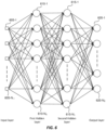
- FIG. 6 depicts an example neural network with an input layer (605) two hidden layers (610 and 615) and one output layer (620).
- a solution to equation (6) can be found using "back propagation.” Note that instead of having a single NN, one may also employ three or more neural networks, one for each one of the color components in the input signals.
- performance can be improved by renormalizing the input signals to the range [-1 1].
- the neural network needs to include
- ⁇ max y max ⁇ i y
- ⁇ max c 0 max ⁇ i c 0
- ⁇ max c 1 max ⁇ i c 1
- ⁇ min y min ⁇ i y
- An L -layer neural-network based mapping can be represented using the following parameters, which can be communicated to a receiver as metadata:
- FIG. 3A depicts an example system for generating an HDR-to-SDR mapping according to an embodiment of global mapping, where the same pixel mapping is performed on the whole image, regardless of the pixel's location.
- the inputs are in YCbCr 4:2:0 format; however, similar architectures are applicable regardless of the color format being used (e.g., YCbCr 4:2:2 or 4:4:4, RGB, ICtCp, and the like).
- down-scaler 310 and up-scaler 315 may be used so that all inputs to the NN units (305) have the same spatial resolution. These upscaling and downscaling functions can be eliminated if the input is in a 4:4:4 format. As depicted in FIG. 3A :
- Each NNM 305 may comprise a single layer (e.g., one layer with 16 nodes, denoted as [16]), or multiple layers (e.g., a [8 4 4] NN).
- Implementation examples for NNM may be found in M. T. Hagan, et al., "Neural Network Design” (2nd Edition), 2014 , or in S. O. Haykin, “Neural Networks and Learning Machines,” (3rd Edition), Pearson, 2008 .
- the MATLAB functions fitnet and train in Matlab's Neural NetworkToolbox may also be used.
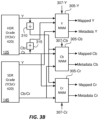
- FIG. 3B depicts an example system for generating an HDR-to-SDR mapping according to an embodiment where pixel mapping is performed at the local level (local mapping).
- the neural network mapping (NNM) units (305) include an additional input 307 representing positional pixel information.
- ( x i , y i ) denote the normalized coordinates for the i -th pixel, i.e. x i ⁇ [0,1] and y i ⁇ [0,1]. These normalized values can be computed by dividing the original coordinates by the corresponding dimensions (e.g., width and height) of the image.
- the luma and chroma components require different processing.
- Y-NNM (305-Y) in input 307-Y, it uses the full resolution ( x i , y i ); however, for chroma, Cb-NNM (305-Cb) and Cr-NNM (305 Cr), in inputs 307-Cb and 307-Cr, they use scaled versions of the original resolution ( x i , y i ) (e.g. x i /2 , y i /2). Note that both coordinates need to be in the normalized [0,1] domain. The only difference is that the location is normalized by different image sizes.
- an encoder may have access to multiple SDR or HDR "grades” or “trims.” Then, as shown in FIG. 3C , the neural network mapping networks may take advantage of the multiple trims to further improve the mapping from one representation to another.
- s k , i s k , i y s k , i c 0 s k , i c 1 T the three-color values of the i -th pixel in the reference image for the k-th grade.
- the input vector needs to include the normalized target brightness value (e.g. in nits), t k ⁇ [0,1] and becomes a 4-input vector.
- mapping problem can be expressed as solving for the mapping function M (), where s i MG ⁇ M v i MG .
- the NNMs in FIG. 3C may also use pixel location information as in FIG. 3B .
- all NNMs may take into consideration HDR and SDR frames from multiple time instances.
- Other image attributes that can be considered in a neural network may include image contrast, image saturation, and edge strength.
- edge detections may be used to improve local tone-mappings.
- 3D Mapping Table 3D-MT or 3DMT
- 3D Mapping Tables were first introduced in U.S. Patent Application Ser. No. 15/725,101, "Inverse Luma/Chroma Mappings with Histogram Transfer and Approximation," filed on Oct. 4, 2017, by B. Wen et al.
- a 3D Mapping Table was derived as an extension of 2D Mapping, where an image in a first dynamic range was mapped into another dynamic range based on the constraint that the cumulative density functions (CDF) of both images should match.
- CDF cumulative density functions
- a 3D-MT table reduces pixel-based computations and can yield mappings that generate output images with improved color accuracy.
- a 3D-MT to be used in neural-networks-based mapping may be constructed as follows.
- first image e.g., an HDR image
- s i s i y s i c 0 s i c 1 T the corresponding i-th pixel in the second image (e.g., an SDR image).
- the number of bins in one color component may be different than the number of bins in the other color components.
- These bins will be used to compute its ( Q y ⁇ Q C 0 ⁇ Q C 1 ) 3D histogram.
- ⁇ Q , v contains a total of Q y Q C 0 Q C 1 bins
- each 3D bin specified by bin index q ( q y ,q C 0 ,q C 1 ) represents the number of pixels having those 3-channel quantized values.
- bin index q ( q y ,q C 0 ,q C 1 ) represents the number of pixels having those 3-channel quantized values.
- For each 3D bin one also computes the sum of each color component in the second image.
- the next step is to identify the 3D histogram bins that have non-zero number of pixels and discard those bins that do not have any pixels. Let q 0 , q 1 ,... q k-1 , be k such bins for which, ⁇ q Q , ⁇ ⁇ 0 . Compute the averages of ⁇ y , q Q , s , ⁇ C 0 , q Q , s , and ⁇ C 1 , q Q , s .
- the original set of v i and s i values is replaced with the pair ⁇ q B and ⁇ ⁇ q Q , s as defined above for valid q values.
- FIG. 4 depicts an example architecture (400) for generating an HDR to SDR mapping using 3D mapping tables and neural networks according to an embodiment.
- the system utilizes two 3D-MTs: a luma 3D-MT (405) and a chroma 3D-MT (410).
- a luma 3D-MT 405
- a chroma 3D-MT 410
- the three neural-network mappings (415), (for luma and chroma) are generated based on the outputs of the two 3D-MTs. For example, in an embodiment, for:
- 3DMTs provides the following advantages: a) One can exercise the neural networks using far fewer points, since the number of bins is much smaller than the number of pixels. This allows for faster convergence, which is very important in real-time applications. b) Generating the 3D-MTs in effect consolidates pixels into bins of "important pixels," thus reducing the effects of biasing the NN decisions by multiple pixels of lower value in terms of image quality.
- the (400) system is equivalent to the one described in FIG. 3A . It can be easily extended to support the architectures in FIG. 3B and FIG. 3C by extending the concept of 3D mapping tables to higher dimensions, e.g. by using a 5D-MT for local mapping ( FIG. 3B ).
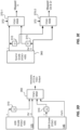
- FIG. 3D depicts a system to generate a global mapping between two color grades using a single YCbCr NNM (350). Given the NNM parameters (372) generated by the system in FIG. 3D, FIG.
- 3E depicts an example predictor (e.g., 250D) which applies the mapping function (as characterized by the parameters of the NN, that is, metadata (372) to reconstruct the original data using YCbCr NNM 370.
- the mapping function as characterized by the parameters of the NN, that is, metadata (372) to reconstruct the original data using YCbCr NNM 370.
- signal 360 source grade
- the mapped YCbCr data represent the predicted HDR data
- signal 360 represents input HDR data
- the mapped YCbCr data represent the predicted SDR data.
- the two YCbCr NNs (370-1, 370-2) are identical, but each one handles the input data slightly differently.
- NNM 370-1 For luma (Y), NNM 370-1 requires input chroma data to be up-sampled to full resolution (same as the resolution of Y). The Cb/Cr output of 370-1 is discarded.
- NNM 370-2 For chroma, NNM 370-2 requires the input luma data to be down-sampled to match the resolution of the chroma components. The luma output of NNM 370-2 may be discarded.
- NNM 370 may be a single, time-shared, NN network.
- FIG. 3E depicts a predictor based on the global mapping of FIG. 3A .
- NNMs (370) in FIG. 3E are now replaced with three distinct NNs, one for Y (380-Y), one for Cb (380-Cb), and one for Cr (380-Cr), each one receiving its own distinct metadata (382-Y/Cb/Cr).
- luma and chroma inputs to each of these NNs are up-sampled or down-sampled appropriately
- FIG. 3F assuming a v (360) to ⁇ mapping:
- computational complexity in all systems may be decreased by employing pixel subsampling both spatially and temporally.
- the neural networks may be solved using sub-sampled frames and/or the results may be used for multiple consecutive frames.
- initialization values may be a simple copy of the solutions from the previous frame.
- NNM metadata include the input normalization parameters and the neural-network parameters. These values are typically floating-point numbers in single or double precision. Metadata overhead can be reduced by applying known in the art lossy or lossless data compression schemes to reduce the amount of metadata overhead data without affecting the efficiency of the mapping.
- Table 4 depicts an example of bitstream syntax to communicate NNM metadata from an encoder (130) to a decoder (150) according to an embodiment.
- the descriptors se(v), u(v), and ue(v), may be defined as in known-in the art specifications for video decoding, such as ITU-T H.265, "High Efficiency Coding.”
- the value of "cmp” denotes the color component, e.g., 0 for Y, 1 for Cb, and 2 for Cr. Additional variables may be defined as follows:
- FIG. 5 shows an example process (500) for deriving an image-mapping function between two images representing the same scene but at different dynamic ranges and/or color gamut.
- the process starts in step 505, wherein a mapping processor, such as predictor 250E, receives two or more images representing the same scene, but at different dynamic ranges, say, a reference input HDR image and one or more derivative grades of an SDR or alternative HDR representations of the same image. Given these inputs, in step 510, the mapping processor decides on which neural network (NN) model to select.
- the mapping processor may select among a variety of NN models, including (but not necessarily limited to): a global mapping model, a local mapping model, a mapping using multiple grades, or a combination of the above.
- each of these models may be characterized by a different number of levels and nodes within each level.
- the selection of the NN model can be done using a variety of methods that take into considerations a number of criteria, including: prior knowledge on the SDR and HDR inputs, available computational and memory resources, and target coding efficiency.
- the NN model may be selected based on whether the value of the residual MSE between the target output and the reference grade it tries to approximate (see equation (6)) satisfies a predetermined threshold.
- the NN parameters e.g., the node weights and biases
- the mapping processor outputs the parameters of the NN model.
- the mapping processor may also output the generated mapped (output) image.
- This mapping process 500 may be repeated at a variety of intervals as deemed necessary to maintain coding efficiency while using available computing resources. For example, when coding video signals, process 500 can be repeated on a per predefined video slice size basis, for each frame, a group of frames, or whenever the prediction residual exceeds a particular threshold.
- Mapping process 500 may use all available input pixels or a sub-sample of those pixels.
- one may use pixels only from every k -th pixel row and every k -th pixel column of the input data, where k is an integer equal or higher than two.
- one may decide to skip input pixels that are below a certain clipping threshold (for example, very close to zero) or pixels that are above a certain saturation threshold (for example, for n -bit data, pixel values that are very close to 2 n -1.)
- a certain clipping threshold for example, very close to zero
- a certain saturation threshold for example, for n -bit data, pixel values that are very close to 2 n -1.
- one may use a combination of such subsampling and thresholding techniques to reduce the pixel sample size and accommodate the computational constrains of a particular implementation.
- Embodiments of the present invention may be implemented with a computer system, systems configured in electronic circuitry and components, an integrated circuit (IC) device such as a microcontroller, a field programmable gate array (FPGA), or another configurable or programmable logic device (PLD), a discrete time or digital signal processor (DSP), an application specific IC (ASIC), and/or apparatus that includes one or more of such systems, devices or components.
- IC integrated circuit
- FPGA field programmable gate array
- PLD configurable or programmable logic device
- DSP discrete time or digital signal processor
- ASIC application specific IC
- the computer and/or IC may perform, control or execute instructions relating to NNM-based mapping, such as those described herein.
- the computer and/or IC may compute, any of a variety of parameters or values that relate to the NNM-based mapping as described herein.
- the image and video dynamic range extension embodiments may be implemented in hardware, software, firmware and various combinations thereof.
- Certain implementations of the invention comprise computer processors which execute software instructions which cause the processors to perform a method of the invention.
- processors in a display, an encoder, a set top box, a transcoder or the like may implement NNM-based mapping methods as described above by executing software instructions in a program memory accessible to the processors.
- the invention may also be provided in the form of a program product.
- the program product may comprise any medium which carries a set of computer-readable signals comprising instructions which, when executed by a data processor, cause the data processor to execute a method of the invention.
- Program products according to the invention may be in any of a wide variety of forms.
- the program product may comprise, for example, physical media such as magnetic data storage media including floppy diskettes, hard disk drives, optical data storage media including CD ROMs, DVDs, electronic data storage media including ROMs, flash RAM, or the like.
- the computer-readable signals on the program product may optionally be compressed or encrypted.
- a component e.g. a software module, processor, assembly, device, circuit, etc.
- reference to that component should be interpreted as including as equivalents of that component any component which performs the function of the described component (e.g., that is functionally equivalent), including components which are not structurally equivalent to the disclosed structure which performs the function in the illustrated example embodiments of the invention.
Landscapes
- Engineering & Computer Science (AREA)
- Physics & Mathematics (AREA)
- Theoretical Computer Science (AREA)
- General Physics & Mathematics (AREA)
- Multimedia (AREA)
- Artificial Intelligence (AREA)
- Evolutionary Computation (AREA)
- Data Mining & Analysis (AREA)
- Signal Processing (AREA)
- Software Systems (AREA)
- Life Sciences & Earth Sciences (AREA)
- General Engineering & Computer Science (AREA)
- Molecular Biology (AREA)
- Mathematical Physics (AREA)
- Computing Systems (AREA)
- General Health & Medical Sciences (AREA)
- Health & Medical Sciences (AREA)
- Biomedical Technology (AREA)
- Biophysics (AREA)
- Computational Linguistics (AREA)
- Computer Vision & Pattern Recognition (AREA)
- Computer Graphics (AREA)
- Geometry (AREA)
- Evolutionary Biology (AREA)
- Bioinformatics & Computational Biology (AREA)
- Bioinformatics & Cheminformatics (AREA)
- Image Processing (AREA)
- Compression Or Coding Systems Of Tv Signals (AREA)
- Facsimile Image Signal Circuits (AREA)
Claims (11)
- Procédé de mappage d'images d'une première plage dynamique à une seconde plage dynamique, dans lequel la première plage dynamique est différente de la seconde plage dynamique, le procédé comprenant :la fourniture d'un ou plusieurs modèles de réseau neuronal (NN), chacun étant adapté pour approximer une image présentant une première plage dynamique en termes d'une image présentant une seconde plage dynamique ;la réception d'une première image dans la première plage dynamique et d'une seconde image dans la seconde plage dynamique, dans lequel les deux images représentent la même scène ;la sélection d'un modèle de réseau neuronal parmi la variété de modèles NN pour déterminer une image de sortie qui approxime la seconde image sur la base de la première image et de la seconde image ;la détermination de valeurs de paramètres du modèle NN sélectionné selon un critère d'optimisation, la première image et la seconde image, dans lequel les paramètres comprennent des poids de nœud et/ou des biais de nœud pour des nœuds des couches du modèle NN sélectionné ; etla sortie des paramètres du modèle NN sélectionné,dans lequel les un ou plusieurs modèles NN comprennent un modèle de mappage global utilisant plusieurs nuances de couleur qui comprend trois réseaux neuronaux, un pour chacune des composantes de couleur des deux images, et chacun des trois réseaux neuronaux reçoit des entrées sur la base de valeurs de pixel des trois composantes de couleur des deux images et une entrée indiquant les nuances de couleur des valeurs de pixel d'entrée, etdans lequel toutes les images d'entrée sont dans un format de couleur 4:2:0 YCbCr, le procédé comprenant en outre :la génération d'une première table de mappage 3D (3DMT) représentant des valeurs de pixel de luminance (Y) et de chrominance (Cb ou Cr) d'entrée des première et seconde images sous la forme d'un mappage de premiers points d'échantillonnage de luminance et de chrominance normalisés dans la première image dans des premiers mappages 3D de luminance et de chrominance moyens dans la seconde image, dans lequel les valeurs de pixel de chrominance d'entrée sont suréchantillonnées pour correspondre à la résolution spatiale des valeurs de pixel de luminance d'entrée ;la génération d'une seconde 3DMT représentant des valeurs de pixel de luminance d'entrée et des valeurs de pixel de chrominance d'entrée des première et seconde images sous la forme d'un mappage de seconds points d'échantillonnage de luminance et de chrominance normalisés dans la première image dans des seconds mappages 3D de luminance et de chrominance moyens dans la seconde image, dans lequel les valeurs de pixel de luminance d'entrée sont sous-échantillonnées pour correspondre à la résolution spatiale des valeurs de pixel de chrominance d'entrée ;la génération des paramètres du réseau neuronal de la composante de sortie Y en lui fournissant en entrée les premiers points d'échantillonnage de luminance et de chrominance normalisés dans la première image et le premier mappage 3D de luminance moyen dans la seconde image ;la génération des paramètres du réseau neuronal de la composante de sortie Cb en lui fournissant en entrée les seconds points d'échantillonnage de luminance et de chrominance normalisés dans la première image et le second mappage 3D Cb moyen dans la seconde image ; etla génération des paramètres du réseau neuronal de la composante de sortie Cr en lui fournissant en entrée les seconds points d'échantillonnage de luminance et de chrominance normalisés dans la première image et le second mappage 3D Cr moyen dans la seconde image,dans lequel chaque 3DMT est générée par :la quantification des trois composantes de couleur (Y, Cr, Cb) de la première image à l'aide d'un nombre fixe de cases pour chaque composante, formant ainsi un histogramme 3D, dans lequel une valeur de case de la case 3D présentant un indice de case q représente un nombre de pixels présentant des valeurs de composante de couleur quantifiées correspondant à cet indice de case q, et la normalisation des valeurs de composante de couleur quantifiées pour obtenir les points d'échantillonnage normalisés,pour chaque case 3D, le calcul d'une somme de valeurs de pixel dans chaque composante de couleur pour des pixels de la seconde image présentant des valeurs de pixel dans la case 3D, et la division de chaque somme par le nombre total de pixels dans la case 3D pour obtenir lesdits mappages moyens.
- Procédé selon la revendication précédente, dans lequel les un ou plusieurs modèles NN comprennent un modèle de mappage local, et le modèle NN de mappage local comprend trois réseaux neuronaux, un pour chacune des composantes de couleur de la première image et de la seconde image, et chacun des trois réseaux neuronaux reçoit des entrées sur la base de valeurs de pixel des trois composantes de couleur de la première image et de la seconde image et une entrée indiquant les coordonnées de pixel des valeurs de pixel d'entrée.
- Procédé selon la revendication 1, dans lequel l'entrée indiquant les nuances de couleur des nuances d'entrée des pixels d'entrée comprend un vecteur normalisé de la luminosité de crête normalisée de chaque nuance de couleur.
- Procédé selon l'une quelconque des revendications 1 et 2, dans lequel les valeurs de pixel d'entrée de chacun des trois réseaux neuronaux sont normalisées entre -1 et 1.
- Procédé selon la revendication 4, dans lequel les paramètres du modèle NN sélectionné comprennent en outre un facteur de gain, une valeur minimale et une valeur maximale pour chaque composante de couleur des valeurs de pixel d'entrée normalisées.
- Procédé selon la revendication 2 ou une quelconque revendication précédente lorsqu'elle dépend de la revendication 2, dans lequel les coordonnées de pixel comprennent une paire d'emplacements (x, y) et des valeurs dans la paire d'emplacements sont normalisées pour être comprises entre 0 et 1.
- Procédé selon une quelconque revendication précédente, dans lequel le critère d'optimisation comprend la réduction au minimum de l'erreur quadratique moyenne entre l'image de sortie et la seconde image d'entrée.
- Procédé selon une quelconque revendication précédente, dans lequel la première plage dynamique est plus basse ou plus haute que la seconde plage dynamique.
- Procédé selon une quelconque revendication précédente, comprenant en outre :la génération de l'image de sortie ;la compression de l'image de sortie pour générer une image codée ; etla combinaison de l'image codée et des paramètres du modèle NN sélectionné pour générer un flux binaire de sortie.
- Procédé de mappage d'une image d'une première plage dynamique à une seconde plage dynamique, dans lequel la première plage dynamique est différente de la seconde plage dynamique, le procédé comprenant :la réception d'un flux binaire compressé comprenant une image codée dans une première plage dynamique et des métadonnées d'image, dans lequel les métadonnées d'image comprennent des paramètres pour un modèle de réseau neuronal (NN) pour mapper l'image codée à une image de sortie, dans lequel les métadonnées d'image comprennent, pour une ou plusieurs composantes de couleur de l'image codée, un nombre de couches de réseau neuronal dans le NN, un nombre de nœuds neuronaux pour au moins une couche, et un poids et un décalage à utiliser avec une fonction d'activation d'un nœud de la au moins une couche ; et
la génération d'une image de sortie sur la base de l'image codée et des paramètres du modèle NN,dans lequel le modèle NN comprend un modèle de mappage global utilisant plusieurs nuances de couleur qui comprend trois réseaux neuronaux, un pour chacune des composantes de couleur de deux images, les deux images représentent la même scène et présentent des plages dynamiques respectives, et chacun des trois réseaux neuronaux reçoit des entrées sur la base de valeurs de pixel des trois composantes de couleur des deux images et une entrée indiquant les nuances de couleur des valeurs de pixel d'entrée,dans lequel les paramètres du modèle NN ont été générés par :la réception d'une première image dans la première plage dynamique et d'une seconde image dans la seconde plage dynamique, dans lequel les deux images représentent la même scène, toutes les images d'entrée étant dans un format de couleur 4:2:0 YCbCr,la génération d'une première table de mappage 3D (3DMT) représentant des valeurs de pixel de luminance (Y) et de chrominance (Cb ou Cr) d'entrée des première et seconde images sous la forme d'un mappage de premiers points d'échantillonnage de luminance et de chrominance normalisés dans la première image dans des premiers mappages 3D de luminance et de chrominance moyens dans la seconde image, dans lequel les valeurs de pixel de chrominance d'entrée sont suréchantillonnées pour correspondre à la résolution spatiale des valeurs de pixel de luminance d'entrée ;la génération d'une seconde 3DMT représentant des valeurs de pixel de luminance d'entrée et des valeurs de pixel de chrominance d'entrée des première et seconde images sous la forme d'un mappage de seconds points d'échantillonnage de luminance et de chrominance normalisés dans la première image dans des seconds mappages 3D de luminance et de chrominance moyens dans la seconde image, dans lequel les valeurs de pixel de luminance d'entrée sont sous-échantillonnées pour correspondre à la résolution spatiale des valeurs de pixel de chrominance d'entrée ;la génération des paramètres du réseau neuronal de la composante de sortie Y en lui fournissant en entrée les premiers points d'échantillonnage de luminance et de chrominance normalisés dans la première image et le premier mappage 3D de luminance moyen dans la seconde image ;la génération des paramètres du réseau neuronal de la composante de sortie Cb en lui fournissant en entrée les seconds points d'échantillonnage de luminance et de chrominance normalisés dans la première image et le second mappage 3D Cb moyen dans la seconde image ; etla génération des paramètres du réseau neuronal de la composante de sortie Cr en lui fournissant en entrée les seconds points d'échantillonnage de luminance et de chrominance normalisés dans la première image et le second mappage 3D Cr moyen dans la seconde image,dans lequel chaque 3DMT est générée par :la quantification des trois composantes de couleur (Y, Cr, Cb) de la première image à l'aide d'un nombre fixe de cases pour chaque composante, formant ainsi un histogramme 3D, dans lequel une valeur de case de la case 3D présentant un indice de case q représente un nombre de pixels présentant des valeurs de composante de couleur quantifiées correspondant à cet indice de case q, et la normalisation des valeurs de composante de couleur quantifiées pour obtenir les points d'échantillonnage normalisés,pour chaque case 3D, le calcul d'une somme de valeurs de pixel dans chaque composante de couleur pour des pixels de la seconde image présentant des valeurs de pixel dans la case 3D, et la division de chaque somme par le nombre total de pixels dans la case 3D pour obtenir lesdits mappages moyens. - Procédé selon la revendication 10, dans lequel les métadonnées d'image comprennent en outre des métadonnées de mise à l'échelle, dans lequel, pour chaque composante de couleur de l'image codée, les métadonnées de mise à l'échelle comprennent un gain, une valeur minimale et une valeur maximale, et le procédé comprend en outre la génération d'une image de sortie de dénormalisation sur la base des métadonnées de mise à l'échelle et de l'image de sortie.
Applications Claiming Priority (3)
| Application Number | Priority Date | Filing Date | Title |
|---|---|---|---|
| US201862654614P | 2018-04-09 | 2018-04-09 | |
| EP18166320 | 2018-04-09 | ||
| PCT/US2019/026406 WO2019199701A1 (fr) | 2018-04-09 | 2019-04-08 | Représentations d'images hdr utilisant des cartographies de réseaux neuronaux |
Publications (2)
| Publication Number | Publication Date |
|---|---|
| EP3776474A1 EP3776474A1 (fr) | 2021-02-17 |
| EP3776474B1 true EP3776474B1 (fr) | 2025-06-11 |
Family
ID=66223879
Family Applications (1)
| Application Number | Title | Priority Date | Filing Date |
|---|---|---|---|
| EP19718564.8A Active EP3776474B1 (fr) | 2018-04-09 | 2019-04-08 | Représentations d'images hdr à l'aide de cartographies de réseau neuronal |
Country Status (7)
| Country | Link |
|---|---|
| US (1) | US11361506B2 (fr) |
| EP (1) | EP3776474B1 (fr) |
| JP (1) | JP7189230B2 (fr) |
| KR (1) | KR102361987B1 (fr) |
| CN (1) | CN112204617B (fr) |
| TW (1) | TWI729377B (fr) |
| WO (1) | WO2019199701A1 (fr) |
Families Citing this family (49)
| Publication number | Priority date | Publication date | Assignee | Title |
|---|---|---|---|---|
| US11501135B2 (en) * | 2018-05-29 | 2022-11-15 | British Cayman Islands Intelligo Technology Inc. | Smart engine with dynamic profiles |
| JP2020005201A (ja) * | 2018-06-29 | 2020-01-09 | 日本放送協会 | 送信装置及び受信装置 |
| WO2021028650A1 (fr) * | 2019-08-13 | 2021-02-18 | University Of Hertfordshire Higher Education Corporation | Prédiction d'images dans la bande visible/infrarouge à l'aide d'images de réflectance/rétrodiffusion radar d'une région terrestre |
| KR102794423B1 (ko) * | 2019-11-15 | 2025-04-11 | 삼성전자주식회사 | 영상 제공 장치 및 이에 의한 영상 제공 방법, 및 디스플레이 장치 및 이에 의한 디스플레이 방법 |
| CN111147857B (zh) * | 2019-12-06 | 2023-01-20 | Oppo广东移动通信有限公司 | 一种图像处理方法、图像处理装置、电子设备和存储介质 |
| JP7443546B2 (ja) * | 2020-02-19 | 2024-03-05 | ドルビー ラボラトリーズ ライセンシング コーポレイション | 画像処理方法、システム及びコンピュータ・プログラム |
| DE102020133963A1 (de) | 2020-03-10 | 2021-09-16 | Samsung Electronics Co., Ltd. | Systeme und Verfahren zur Abbildrauschunterdrückung unter Verwendung von tiefen gefalteten Netzwerken |
| US11508037B2 (en) * | 2020-03-10 | 2022-11-22 | Samsung Electronics Co., Ltd. | Systems and methods for image denoising using deep convolutional networks |
| CN111401247B (zh) * | 2020-03-17 | 2023-07-28 | 杭州小影创新科技股份有限公司 | 一种基于级联卷积神经网络的人像分割方法 |
| US11375204B2 (en) * | 2020-04-07 | 2022-06-28 | Nokia Technologies Oy | Feature-domain residual for video coding for machines |
| US11223841B2 (en) * | 2020-05-29 | 2022-01-11 | Samsung Electronics Co., Ltd. | Apparatus and method for performing artificial intelligence encoding and artificial intelligence decoding on image |
| CN111970564B (zh) * | 2020-08-26 | 2023-03-24 | 展讯通信(上海)有限公司 | Hdr视频显示处理的优化方法及装置、存储介质、终端 |
| JP7583926B2 (ja) * | 2020-11-19 | 2024-11-14 | ホアウェイ・テクノロジーズ・カンパニー・リミテッド | 機械学習を基にしたピクチャコーディングにおけるクロマサブサンプリングフォーマット取り扱いのための方法 |
| CN116508320A (zh) * | 2020-11-19 | 2023-07-28 | 华为技术有限公司 | 基于机器学习的图像译码中的色度子采样格式处理方法 |
| WO2022119333A1 (fr) * | 2020-12-02 | 2022-06-09 | 현대자동차주식회사 | Codec vidéo utilisant un modèle d'apprentissage profond basé sur des blocs |
| JP2022099651A (ja) * | 2020-12-23 | 2022-07-05 | ソニーセミコンダクタソリューションズ株式会社 | 画像生成装置、画像生成方法、およびプログラム |
| CN116648906A (zh) * | 2020-12-24 | 2023-08-25 | 华为技术有限公司 | 通过指示特征图数据进行编码 |
| US11528435B2 (en) | 2020-12-25 | 2022-12-13 | Industrial Technology Research Institute | Image dehazing method and image dehazing apparatus using the same |
| KR102374069B1 (ko) * | 2021-01-06 | 2022-03-11 | 아주대학교산학협력단 | Hdr 이미지 생성 장치 및 방법 |
| CN113496529A (zh) * | 2021-03-23 | 2021-10-12 | 北京迈格威科技有限公司 | 显示控制方法、装置和电子系统 |
| US11967042B2 (en) * | 2021-05-11 | 2024-04-23 | Synaptics Incorporated | Data pre-processing for low-light images |
| JP7641186B2 (ja) * | 2021-06-23 | 2025-03-06 | シャープ株式会社 | 動画像符号化装置、および、動画像復号装置 |
| TWI783594B (zh) * | 2021-07-26 | 2022-11-11 | 國立清華大學 | 多目標神經網路演化方法及裝置 |
| JP7707411B2 (ja) * | 2021-07-29 | 2025-07-14 | ドルビー ラボラトリーズ ライセンシング コーポレイション | 画像のダイナミックレンジ変換及び表示管理のためのニューラルネットワーク |
| US12041248B2 (en) * | 2021-08-02 | 2024-07-16 | Mediatek Singapore Pte. Ltd. | Color component processing in down-sample video coding |
| CN113781318A (zh) * | 2021-08-02 | 2021-12-10 | 中国科学院深圳先进技术研究院 | 一种图像颜色映射方法、装置、终端设备及存储介质 |
| US12260526B2 (en) | 2021-08-13 | 2025-03-25 | Samsung Electronics Co., Ltd. | Self-emitting display (SED) burn-in prevention based on stationary luminance reduction |
| US12211434B2 (en) | 2021-08-13 | 2025-01-28 | Samsung Electronics Co., Ltd. | Detecting stationary regions for organic light emitting diode (OLED) television (TV) luminance reduction |
| US12367565B2 (en) | 2021-08-18 | 2025-07-22 | Samsung Electronics Co., Ltd. | Efficient inverse tone mapping network for standard dynamic range (SDR) to high dynamic range (HDR) conversion on HDR display |
| US12506894B2 (en) | 2021-08-30 | 2025-12-23 | Dolby Laboratories Licensing Corporation | Reshaper for learning based image/video coding |
| KR20230055264A (ko) * | 2021-10-18 | 2023-04-25 | 삼성전자주식회사 | 디스플레이 장치 및 그 제어 방법 |
| CN116091335B (zh) * | 2021-11-08 | 2026-03-13 | 创惟科技股份有限公司 | 图像处理方法及图像处理装置 |
| US12555201B2 (en) * | 2021-12-14 | 2026-02-17 | Netflix, Inc. | Techniques for component-based image preprocessing |
| CN114359083B (zh) * | 2021-12-24 | 2022-11-29 | 北京航空航天大学 | 一种面向干扰环境的高动态热红外图像自适应预处理方法 |
| CN114490647B (zh) * | 2022-01-14 | 2024-12-10 | 深圳市汇川技术股份有限公司 | 参数值的获取方法、控制器、终端设备及可读存储介质 |
| CN114422718B (zh) * | 2022-01-19 | 2022-12-13 | 北京百度网讯科技有限公司 | 一种视频转换方法、装置、电子设备及存储介质 |
| WO2023205548A1 (fr) | 2022-04-21 | 2023-10-26 | Dolby Laboratories Licensing Corporation | Génération d'une image hdr à partir d'images brutes et sdr correspondantes de la caméra |
| US12051364B2 (en) | 2022-05-06 | 2024-07-30 | Samsung Electronics Co., Ltd. | Organic light emitting diode (OLED) burn-in prevention based on stationary pixel and luminance reduction |
| US20250316291A1 (en) * | 2022-05-16 | 2025-10-09 | Dolby Laboratories Licensing Corporation | Trim pass metadata prediction in video sequences using neural networks |
| EP4283459A1 (fr) * | 2022-05-24 | 2023-11-29 | Koninklijke Philips N.V. | Mélange d'éléments graphiques secondaires dans des images hdr |
| KR102465841B1 (ko) * | 2022-08-10 | 2022-11-10 | 주식회사 고업 | 딥러닝을 이용한 sdr 콘텐츠의 hdr10+ 콘텐츠 변경 시스템 |
| CN115422986B (zh) * | 2022-11-07 | 2023-08-22 | 深圳传音控股股份有限公司 | 处理方法、处理设备及存储介质 |
| CN119172546A (zh) * | 2023-06-20 | 2024-12-20 | 京东方科技集团股份有限公司 | 图像处理方法、系统、目标模型的获取方法、设备及介质 |
| US20250113035A1 (en) * | 2023-10-02 | 2025-04-03 | Tencent America LLC | Sample mapping for low dynamic range-based image and video coding |
| CN119919329A (zh) * | 2023-10-31 | 2025-05-02 | 华为技术有限公司 | 图像编码、图像解码方法及相关装置 |
| GB2635211B (en) * | 2023-11-03 | 2026-03-11 | Sony Interactive Entertainment Inc | Methods and devices for texture coding |
| EP4612646A1 (fr) * | 2024-01-12 | 2025-09-10 | Dream CHIP Technologies GmbH | Procédé, programme informatique et dispositif électronique de mappage tonal sur la base d'un réseau neuronal |
| US20250310508A1 (en) * | 2024-03-27 | 2025-10-02 | Adeia Guides Inc. | Single format frame packing and video compression for backward compatible distribution of 3d hdr content |
| JP7760652B1 (ja) | 2024-06-27 | 2025-10-27 | キヤノン株式会社 | 画像処理方法、画像処理装置、及びプログラム |
Family Cites Families (26)
| Publication number | Priority date | Publication date | Assignee | Title |
|---|---|---|---|---|
| US7149262B1 (en) | 2000-07-06 | 2006-12-12 | The Trustees Of Columbia University In The City Of New York | Method and apparatus for enhancing data resolution |
| US6879731B2 (en) | 2003-04-29 | 2005-04-12 | Microsoft Corporation | System and process for generating high dynamic range video |
| US7142723B2 (en) | 2003-07-18 | 2006-11-28 | Microsoft Corporation | System and process for generating high dynamic range images from multiple exposures of a moving scene |
| US20090317017A1 (en) | 2008-06-20 | 2009-12-24 | The Hong Kong University Of Science And Technology | Image characteristic oriented tone mapping for high dynamic range images |
| JP5247337B2 (ja) * | 2008-10-02 | 2013-07-24 | キヤノン株式会社 | 画像認識装置および画像認識方法 |
| TW201036453A (en) * | 2009-03-25 | 2010-10-01 | Micro Star Int Co Ltd | Method and electronic device to produce high dynamic range image |
| PL4120264T3 (pl) | 2010-01-19 | 2023-11-20 | Dolby International Ab | Transpozycja harmonicznych oparta na ulepszonym bloku pod-pasma |
| WO2012004709A1 (fr) | 2010-07-06 | 2012-01-12 | Koninklijke Philips Electronics N.V. | Génération d'images à grande gamme dynamique à partir d'images à faible gamme dynamique |
| CN107105229B9 (zh) | 2011-04-14 | 2020-03-31 | 杜比实验室特许公司 | 图像解码方法、视频解码器和非暂态计算机可读存储介质 |
| PL2945377T3 (pl) | 2012-01-24 | 2019-04-30 | Dolby Laboratories Licensing Corp | Element predykcji kanału fragmentowego przenikania kolorów |
| EP2873237B1 (fr) | 2012-07-13 | 2022-03-30 | Koninklijke Philips N.V. | Procédés et dispositifs de décodage d'image hdr améliorés |
| KR102105645B1 (ko) * | 2012-10-08 | 2020-05-04 | 코닌클리케 필립스 엔.브이. | 색상 제한들을 통한 루미넌스 변화 이미지 처리 |
| US9418331B2 (en) * | 2013-10-28 | 2016-08-16 | Qualcomm Incorporated | Methods and apparatus for tagging classes using supervised learning |
| KR20230062888A (ko) | 2014-02-26 | 2023-05-09 | 인터디지털 브이씨 홀딩스 인코포레이티드 | Hdr 이미지들을 인코딩 및 디코딩하기 위한 방법 및 장치 |
| CN108182672A (zh) | 2014-05-28 | 2018-06-19 | 皇家飞利浦有限公司 | 用于对hdr图像进行编码的方法和装置以及用于使用这样的编码图像的方法和装置 |
| US10136147B2 (en) * | 2014-06-11 | 2018-11-20 | Dolby Laboratories Licensing Corporation | Efficient transcoding for backward-compatible wide dynamic range codec |
| JP6577703B2 (ja) | 2014-08-05 | 2019-09-18 | キヤノン株式会社 | 画像処理装置及び画像処理方法、プログラム、記憶媒体 |
| US9607366B1 (en) | 2014-12-19 | 2017-03-28 | Amazon Technologies, Inc. | Contextual HDR determination |
| US10015491B2 (en) | 2015-04-06 | 2018-07-03 | Dolby Laboratories Licensing Corporation | In-loop block-based image reshaping in high dynamic range video coding |
| US9794540B2 (en) | 2015-04-17 | 2017-10-17 | Google Inc. | Hardware-based convolutional color correction in digital images |
| JP6320440B2 (ja) | 2015-08-04 | 2018-05-09 | ドルビー ラボラトリーズ ライセンシング コーポレイション | ハイダイナミックレンジ信号のための信号再構成 |
| EP3131284A1 (fr) | 2015-08-13 | 2017-02-15 | Thomson Licensing | Procédés, systèmes et appareil pour mappage de teintes inverse hdr vers hdr |
| EP3220349A1 (fr) | 2016-03-16 | 2017-09-20 | Thomson Licensing | Procédés, appareil et systèmes d'extension de gamme dynamique élevée (« hdr« ) hdr au mappage de tonalité hdr |
| US9639935B1 (en) | 2016-05-25 | 2017-05-02 | Gopro, Inc. | Apparatus and methods for camera alignment model calibration |
| CN109964238A (zh) | 2016-09-30 | 2019-07-02 | 渊慧科技有限公司 | 使用神经网络生成视频帧 |
| US10264287B2 (en) * | 2016-10-05 | 2019-04-16 | Dolby Laboratories Licensing Corporation | Inverse luma/chroma mappings with histogram transfer and approximation |
-
2019
- 2019-04-08 EP EP19718564.8A patent/EP3776474B1/fr active Active
- 2019-04-08 CN CN201980035144.1A patent/CN112204617B/zh active Active
- 2019-04-08 JP JP2020555148A patent/JP7189230B2/ja active Active
- 2019-04-08 US US17/045,941 patent/US11361506B2/en active Active
- 2019-04-08 WO PCT/US2019/026406 patent/WO2019199701A1/fr not_active Ceased
- 2019-04-08 KR KR1020207032222A patent/KR102361987B1/ko active Active
- 2019-04-09 TW TW108112378A patent/TWI729377B/zh active
Also Published As
| Publication number | Publication date |
|---|---|
| EP3776474A1 (fr) | 2021-02-17 |
| TWI729377B (zh) | 2021-06-01 |
| CN112204617A (zh) | 2021-01-08 |
| JP7189230B2 (ja) | 2022-12-13 |
| TW201944357A (zh) | 2019-11-16 |
| KR20200142035A (ko) | 2020-12-21 |
| KR102361987B1 (ko) | 2022-02-14 |
| JP2021521517A (ja) | 2021-08-26 |
| US11361506B2 (en) | 2022-06-14 |
| WO2019199701A1 (fr) | 2019-10-17 |
| US20210150812A1 (en) | 2021-05-20 |
| CN112204617B (zh) | 2023-09-05 |
Similar Documents
| Publication | Publication Date | Title |
|---|---|---|
| EP3776474B1 (fr) | Représentations d'images hdr à l'aide de cartographies de réseau neuronal | |
| US10659749B2 (en) | Efficient histogram-based luma look matching | |
| US10575028B2 (en) | Coding of high dynamic range video using segment-based reshaping | |
| US9924171B2 (en) | Layer decomposition in hierarchical VDR coding | |
| US10972759B2 (en) | Color appearance preservation in video codecs | |
| US20210350512A1 (en) | Automatic display management metadata generation for gaming and/or sdr+ contents | |
| EP4222969B1 (fr) | Remodelage local adaptatif pour conversion ascendante sdr-hdr | |
| US9877032B2 (en) | Weighted multi-band cross color channel predictor | |
| WO2018049335A1 (fr) | Codage vidéo à plage dynamique élevée à l'aide d'un remodelage basé sur des segments | |
| US20220295020A1 (en) | Electro-optical transfer function conversion and signal legalization | |
| US12177459B2 (en) | Rate-control-aware reshaping in HDR imaging | |
| US12506894B2 (en) | Reshaper for learning based image/video coding | |
| US12387305B2 (en) | Color transformation for HDR video with a coding-efficiency constraint | |
| HK1228137A1 (zh) | 分層vdr編譯碼中的層分解 | |
| HK1228137A (en) | Layer decomposition in hierarchical vdr coding |
Legal Events
| Date | Code | Title | Description |
|---|---|---|---|
| STAA | Information on the status of an ep patent application or granted ep patent |
Free format text: STATUS: UNKNOWN |
|
| STAA | Information on the status of an ep patent application or granted ep patent |
Free format text: STATUS: THE INTERNATIONAL PUBLICATION HAS BEEN MADE |
|
| PUAI | Public reference made under article 153(3) epc to a published international application that has entered the european phase |
Free format text: ORIGINAL CODE: 0009012 |
|
| STAA | Information on the status of an ep patent application or granted ep patent |
Free format text: STATUS: REQUEST FOR EXAMINATION WAS MADE |
|
| 17P | Request for examination filed |
Effective date: 20201109 |
|
| AK | Designated contracting states |
Kind code of ref document: A1 Designated state(s): AL AT BE BG CH CY CZ DE DK EE ES FI FR GB GR HR HU IE IS IT LI LT LU LV MC MK MT NL NO PL PT RO RS SE SI SK SM TR |
|
| AX | Request for extension of the european patent |
Extension state: BA ME |
|
| DAV | Request for validation of the european patent (deleted) | ||
| DAX | Request for extension of the european patent (deleted) | ||
| STAA | Information on the status of an ep patent application or granted ep patent |
Free format text: STATUS: EXAMINATION IS IN PROGRESS |
|
| 17Q | First examination report despatched |
Effective date: 20220722 |
|
| P01 | Opt-out of the competence of the unified patent court (upc) registered |
Effective date: 20230417 |
|
| GRAP | Despatch of communication of intention to grant a patent |
Free format text: ORIGINAL CODE: EPIDOSNIGR1 |
|
| STAA | Information on the status of an ep patent application or granted ep patent |
Free format text: STATUS: GRANT OF PATENT IS INTENDED |
|
| INTG | Intention to grant announced |
Effective date: 20250131 |
|
| GRAS | Grant fee paid |
Free format text: ORIGINAL CODE: EPIDOSNIGR3 |
|
| GRAA | (expected) grant |
Free format text: ORIGINAL CODE: 0009210 |
|
| STAA | Information on the status of an ep patent application or granted ep patent |
Free format text: STATUS: THE PATENT HAS BEEN GRANTED |
|
| AK | Designated contracting states |
Kind code of ref document: B1 Designated state(s): AL AT BE BG CH CY CZ DE DK EE ES FI FR GB GR HR HU IE IS IT LI LT LU LV MC MK MT NL NO PL PT RO RS SE SI SK SM TR |
|
| REG | Reference to a national code |
Ref country code: GB Ref legal event code: FG4D |
|
| REG | Reference to a national code |
Ref country code: CH Ref legal event code: EP |
|
| REG | Reference to a national code |
Ref country code: DE Ref legal event code: R096 Ref document number: 602019071011 Country of ref document: DE |
|
| REG | Reference to a national code |
Ref country code: IE Ref legal event code: FG4D |
|
| PG25 | Lapsed in a contracting state [announced via postgrant information from national office to epo] |
Ref country code: ES Free format text: LAPSE BECAUSE OF FAILURE TO SUBMIT A TRANSLATION OF THE DESCRIPTION OR TO PAY THE FEE WITHIN THE PRESCRIBED TIME-LIMIT Effective date: 20250611 Ref country code: FI Free format text: LAPSE BECAUSE OF FAILURE TO SUBMIT A TRANSLATION OF THE DESCRIPTION OR TO PAY THE FEE WITHIN THE PRESCRIBED TIME-LIMIT Effective date: 20250611 |
|
| REG | Reference to a national code |
Ref country code: LT Ref legal event code: MG9D |
|
| PG25 | Lapsed in a contracting state [announced via postgrant information from national office to epo] |
Ref country code: NO Free format text: LAPSE BECAUSE OF FAILURE TO SUBMIT A TRANSLATION OF THE DESCRIPTION OR TO PAY THE FEE WITHIN THE PRESCRIBED TIME-LIMIT Effective date: 20250911 Ref country code: GR Free format text: LAPSE BECAUSE OF FAILURE TO SUBMIT A TRANSLATION OF THE DESCRIPTION OR TO PAY THE FEE WITHIN THE PRESCRIBED TIME-LIMIT Effective date: 20250912 |
|
| REG | Reference to a national code |
Ref country code: NL Ref legal event code: MP Effective date: 20250611 |
|
| PG25 | Lapsed in a contracting state [announced via postgrant information from national office to epo] |
Ref country code: BG Free format text: LAPSE BECAUSE OF FAILURE TO SUBMIT A TRANSLATION OF THE DESCRIPTION OR TO PAY THE FEE WITHIN THE PRESCRIBED TIME-LIMIT Effective date: 20250611 |
|
| PG25 | Lapsed in a contracting state [announced via postgrant information from national office to epo] |
Ref country code: HR Free format text: LAPSE BECAUSE OF FAILURE TO SUBMIT A TRANSLATION OF THE DESCRIPTION OR TO PAY THE FEE WITHIN THE PRESCRIBED TIME-LIMIT Effective date: 20250611 |
|
| PG25 | Lapsed in a contracting state [announced via postgrant information from national office to epo] |
Ref country code: RS Free format text: LAPSE BECAUSE OF FAILURE TO SUBMIT A TRANSLATION OF THE DESCRIPTION OR TO PAY THE FEE WITHIN THE PRESCRIBED TIME-LIMIT Effective date: 20250911 |
|
| PG25 | Lapsed in a contracting state [announced via postgrant information from national office to epo] |
Ref country code: LV Free format text: LAPSE BECAUSE OF FAILURE TO SUBMIT A TRANSLATION OF THE DESCRIPTION OR TO PAY THE FEE WITHIN THE PRESCRIBED TIME-LIMIT Effective date: 20250611 |
|
| PG25 | Lapsed in a contracting state [announced via postgrant information from national office to epo] |
Ref country code: NL Free format text: LAPSE BECAUSE OF FAILURE TO SUBMIT A TRANSLATION OF THE DESCRIPTION OR TO PAY THE FEE WITHIN THE PRESCRIBED TIME-LIMIT Effective date: 20250611 |
|
| PG25 | Lapsed in a contracting state [announced via postgrant information from national office to epo] |
Ref country code: PT Free format text: LAPSE BECAUSE OF FAILURE TO SUBMIT A TRANSLATION OF THE DESCRIPTION OR TO PAY THE FEE WITHIN THE PRESCRIBED TIME-LIMIT Effective date: 20251013 |
|
| REG | Reference to a national code |
Ref country code: AT Ref legal event code: MK05 Ref document number: 1802889 Country of ref document: AT Kind code of ref document: T Effective date: 20250611 |
|
| PG25 | Lapsed in a contracting state [announced via postgrant information from national office to epo] |
Ref country code: IS Free format text: LAPSE BECAUSE OF FAILURE TO SUBMIT A TRANSLATION OF THE DESCRIPTION OR TO PAY THE FEE WITHIN THE PRESCRIBED TIME-LIMIT Effective date: 20251011 |
|
| PG25 | Lapsed in a contracting state [announced via postgrant information from national office to epo] |
Ref country code: AT Free format text: LAPSE BECAUSE OF FAILURE TO SUBMIT A TRANSLATION OF THE DESCRIPTION OR TO PAY THE FEE WITHIN THE PRESCRIBED TIME-LIMIT Effective date: 20250611 Ref country code: SM Free format text: LAPSE BECAUSE OF FAILURE TO SUBMIT A TRANSLATION OF THE DESCRIPTION OR TO PAY THE FEE WITHIN THE PRESCRIBED TIME-LIMIT Effective date: 20250611 |
|
| PG25 | Lapsed in a contracting state [announced via postgrant information from national office to epo] |
Ref country code: CZ Free format text: LAPSE BECAUSE OF FAILURE TO SUBMIT A TRANSLATION OF THE DESCRIPTION OR TO PAY THE FEE WITHIN THE PRESCRIBED TIME-LIMIT Effective date: 20250611 |
|
| PG25 | Lapsed in a contracting state [announced via postgrant information from national office to epo] |
Ref country code: PL Free format text: LAPSE BECAUSE OF FAILURE TO SUBMIT A TRANSLATION OF THE DESCRIPTION OR TO PAY THE FEE WITHIN THE PRESCRIBED TIME-LIMIT Effective date: 20250611 |
|
| PG25 | Lapsed in a contracting state [announced via postgrant information from national office to epo] |
Ref country code: EE Free format text: LAPSE BECAUSE OF FAILURE TO SUBMIT A TRANSLATION OF THE DESCRIPTION OR TO PAY THE FEE WITHIN THE PRESCRIBED TIME-LIMIT Effective date: 20250611 |
|
| PG25 | Lapsed in a contracting state [announced via postgrant information from national office to epo] |
Ref country code: SK Free format text: LAPSE BECAUSE OF FAILURE TO SUBMIT A TRANSLATION OF THE DESCRIPTION OR TO PAY THE FEE WITHIN THE PRESCRIBED TIME-LIMIT Effective date: 20250611 Ref country code: RO Free format text: LAPSE BECAUSE OF FAILURE TO SUBMIT A TRANSLATION OF THE DESCRIPTION OR TO PAY THE FEE WITHIN THE PRESCRIBED TIME-LIMIT Effective date: 20250611 |
|
| PGFP | Annual fee paid to national office [announced via postgrant information from national office to epo] |
Ref country code: GB Payment date: 20260319 Year of fee payment: 8 |
|
| PG25 | Lapsed in a contracting state [announced via postgrant information from national office to epo] |
Ref country code: DK Free format text: LAPSE BECAUSE OF FAILURE TO SUBMIT A TRANSLATION OF THE DESCRIPTION OR TO PAY THE FEE WITHIN THE PRESCRIBED TIME-LIMIT Effective date: 20250611 |
|
| PG25 | Lapsed in a contracting state [announced via postgrant information from national office to epo] |
Ref country code: IT Free format text: LAPSE BECAUSE OF FAILURE TO SUBMIT A TRANSLATION OF THE DESCRIPTION OR TO PAY THE FEE WITHIN THE PRESCRIBED TIME-LIMIT Effective date: 20250611 |
|
| PLBE | No opposition filed within time limit |
Free format text: ORIGINAL CODE: 0009261 |
|
| STAA | Information on the status of an ep patent application or granted ep patent |
Free format text: STATUS: NO OPPOSITION FILED WITHIN TIME LIMIT |
|
| PGFP | Annual fee paid to national office [announced via postgrant information from national office to epo] |
Ref country code: FR Payment date: 20260319 Year of fee payment: 8 |
|
| REG | Reference to a national code |
Ref country code: CH Ref legal event code: L10 Free format text: ST27 STATUS EVENT CODE: U-0-0-L10-L00 (AS PROVIDED BY THE NATIONAL OFFICE) Effective date: 20260423 |