EP3776503B1 - Verfahren und vorrichtung zur identifizierung des kraftstofftyps und übertragung - Google Patents
Verfahren und vorrichtung zur identifizierung des kraftstofftyps und übertragung Download PDFInfo
- Publication number
- EP3776503B1 EP3776503B1 EP19815001.3A EP19815001A EP3776503B1 EP 3776503 B1 EP3776503 B1 EP 3776503B1 EP 19815001 A EP19815001 A EP 19815001A EP 3776503 B1 EP3776503 B1 EP 3776503B1
- Authority
- EP
- European Patent Office
- Prior art keywords
- fuel
- location
- sensor
- type
- gas
- Prior art date
- Legal status (The legal status is an assumption and is not a legal conclusion. Google has not performed a legal analysis and makes no representation as to the accuracy of the status listed.)
- Active
Links
Images


Classifications
-
- B—PERFORMING OPERATIONS; TRANSPORTING
- B67—OPENING, CLOSING OR CLEANING BOTTLES, JARS OR SIMILAR CONTAINERS; LIQUID HANDLING
- B67D—DISPENSING, DELIVERING OR TRANSFERRING LIQUIDS, NOT OTHERWISE PROVIDED FOR
- B67D7/00—Apparatus or devices for transferring liquids from bulk storage containers or reservoirs into vehicles or into portable containers, e.g. for retail sale purposes
- B67D7/04—Apparatus or devices for transferring liquids from bulk storage containers or reservoirs into vehicles or into portable containers, e.g. for retail sale purposes for transferring fuels, lubricants or mixed fuels and lubricants
-
- B—PERFORMING OPERATIONS; TRANSPORTING
- B67—OPENING, CLOSING OR CLEANING BOTTLES, JARS OR SIMILAR CONTAINERS; LIQUID HANDLING
- B67D—DISPENSING, DELIVERING OR TRANSFERRING LIQUIDS, NOT OTHERWISE PROVIDED FOR
- B67D7/00—Apparatus or devices for transferring liquids from bulk storage containers or reservoirs into vehicles or into portable containers, e.g. for retail sale purposes
- B67D7/06—Details or accessories
- B67D7/32—Arrangements of safety or warning devices; Means for preventing unauthorised delivery of liquid
- B67D7/34—Means for preventing unauthorised delivery of liquid
- B67D7/342—Means for preventing unauthorised delivery of liquid by discriminating the kind of liquid by analysis or by physical properties, e.g. vapour-pressure
-
- G—PHYSICS
- G06—COMPUTING OR CALCULATING; COUNTING
- G06Q—INFORMATION AND COMMUNICATION TECHNOLOGY [ICT] SPECIALLY ADAPTED FOR ADMINISTRATIVE, COMMERCIAL, FINANCIAL, MANAGERIAL OR SUPERVISORY PURPOSES; SYSTEMS OR METHODS SPECIALLY ADAPTED FOR ADMINISTRATIVE, COMMERCIAL, FINANCIAL, MANAGERIAL OR SUPERVISORY PURPOSES, NOT OTHERWISE PROVIDED FOR
- G06Q20/00—Payment architectures, schemes or protocols
- G06Q20/08—Payment architectures
- G06Q20/14—Payment architectures specially adapted for billing systems
- G06Q20/145—Payments according to the detected use or quantity
-
- G—PHYSICS
- G07—CHECKING-DEVICES
- G07F—COIN-FREED OR LIKE APPARATUS
- G07F13/00—Coin-freed apparatus for controlling dispensing or fluids, semiliquids or granular material from reservoirs
- G07F13/02—Coin-freed apparatus for controlling dispensing or fluids, semiliquids or granular material from reservoirs by volume
- G07F13/025—Coin-freed apparatus for controlling dispensing or fluids, semiliquids or granular material from reservoirs by volume wherein the volume is determined during delivery
-
- G—PHYSICS
- G01—MEASURING; TESTING
- G01N—INVESTIGATING OR ANALYSING MATERIALS BY DETERMINING THEIR CHEMICAL OR PHYSICAL PROPERTIES
- G01N33/00—Investigating or analysing materials by specific methods not covered by groups G01N1/00 - G01N31/00
- G01N33/26—Oils; Viscous liquids; Paints; Inks
- G01N33/28—Oils, i.e. hydrocarbon liquids
Definitions
- the present invention relates to a control method and apparatus for identifying a fuel type such as gasoline or diesel fuel, and providing that the transfer thereof from a first location to a second location involves the same type of fuel.
- US 4838323A describes that the control between two types of fuel such as gasoline and diesel fuel may be realized by a sensor system that can detect the difference in vapor pressure between them and a fuel cut-off apparatus that can communicate with such system.
- said sensor system can make detection by sampling the fuel inside the fuel tank of an automobile.
- US 6341629A discloses a method for controlling the movement of a liquid from a first location to a second location via a dispenser for the liquid located in a liquid line between the first and second location wherein the dispenser includes a nozzle, an internal liquid conduit, a valve, a body portion, a hollow annular collar and a first detector.
- the first detector is located in the collar which is positioned around the nozzle or between the nozzle and the body portion such that the first detector is in vapor communication with a vapor space above the second location.
- the vapor from the vapor space is analyzed by withdrawing the vapor past the first detector and using the results of the analysis to control the operation of the valve, thereby determining as to whether fuel transfer will be made or not.
- US 5209275A relates to a fuel dispensing apparatus which includes a detecting element for detecting the type of fuel from the gas vaporized from such fuel remaining in a storage tank to be supplied with fuel.
- An apparatus according to the preamble of claim 7 is known for example from DE 10 2011 112417 A1 or from EP 0566 345 A1 .
- the object of the invention is to effectively identify of a fuel type.
- Further object of the invention is to provide effective prevention of faulty fuel transfer from a first location to a second location.
- the present invention relates to a method for controlling the transfer of a known-type fuel from a first location to a second location with an unknown type, comprising the following steps of:
- the type of the fuel in the first location may not be previously known but the type of the fuel in the second location may be previously known.
- the type of the fuel in the first location may be determined as explained above and the control of the fuel transfer may be made accordingly.
- the method of the invention may be adapted to a fuel vapor recovery system or such system may involve the method of the invention.
- the fuel types in the first and second location may not be previously known.
- the type of the fuel in both locations may be determined as explained above and the control of the fuel transfer may be made accordingly.
- the density measurement of the fuel vapor and the temperature and/or pressure measurement may be made in an environment where the gaseous form is open to the atmosphere.
- the gaseous form will not be subject to any pre-treatment before the measurement of density and temperature and/or pressure, such as heating or pressurization.
- the first location is a fuel dispenser whereas the second location is the fuel tank of a land vehicle.
- the first location is the tank of a fuel truck whereas the second location is the (underground) tank of a gas station.
- an apparatus for controlling the transfer of a specific type of fuel from a first location to a second location comprising a sensor device for detecting the fuel type in one of said locations and a controller communicating with said sensor device, characterized in that the sensor device comprises a gas sensor that can detect the density of the gaseous form of the fuel in said location and at least one gaseous state sensor that can detect the temperature and/or pressure of the gaseous form of the fuel in said location, and that said controller is configured to compare the data received from said sensor device with a data set comprising predetermined reference values or to conduct a mathematical modeling.
- the total mass of the volatile fuel (vapor) may be obtained based on 1 mole of mixture by multiplying the molar fraction by the total molar weight.
- the total volatile organic compounds mass in unit volume will reveal the VOC value. This calculated value is specific to gasoline or diesel, thus the fuel type which is close to the result read by VOC may be determined.
- an apparatus for controlling the transfer of a specific type of fuel from a first location to a second location comprising a sensor device for detecting the fuel type in a location and a controller communicating with said sensor device, characterized in that said sensor device comprises a gas intake, a gas outlet, a first chamber, a second chamber, at least one membrane arranged to separate said chambers, at least one first gas sensor coupled to said first chamber and at least one second gas sensor coupled to said second chamber.
- Said computer program product stored on a data carrier SERVER.
- Said computer program product comprises commands that perform a method according to the invention when operated in a system for controlling the transfer of a fuel present in a first location to a second location.
- the first location may be a fuel dispenser (7) and the second location may be the fuel tank of a land vehicle.
- the second location may be the fuel tank of a land vehicle.
- it is prior information as to which type of fuel is supplied from a particular fuel dispenser (7).
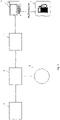
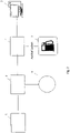
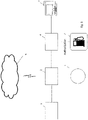
- Such information may be kept in a controller memory inside the main device which shall be described below or it may be stored in an automation computer (5) at the gas station as shown in Fig. 1 or in a memory connected to the fuel dispenser central processor as shown in Fig. 2 or a remote computer such as a cloud server (6) as shown in Fig. 3 .
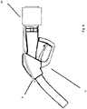
- a main device (10) which is preferably detachably connected to the dispenser nozzle (8) as shown in Fig. 4 or 5 , may be used for determining the fuel type in the fuel tank of the land vehicle.
- Said main device (10) basically comprises a sensor device (11) comprising a gas sensor (1) and a state sensor (3) as well as a controller (2) that can communicate with it.
- the sensor device is preferably connected to a suction tube (9) extending towards the end of the dispenser nozzle (8).
- the main device (10) may further comprise a fan for transmitting fuel vapor to the sensor device and a battery for operating same.
- the gas sensor (1) may be a known VOC sensor or MEMS metal oxide sensor or air quality sensor or MEMS sensor or a combination thereof. When a plurality of sensors are used, they may be combined by a known method such as sensor fusion technique for generating more accurate results in the determination of gas type.
- the controller (2) may at least be a microprocessor-based electronic unit having a memory unit, such as a microcontroller.
- a predetermined data set is recorded as to the extent of volatility the gaseous form of each fuel type has under certain temperature and/or pressure conditions. Further, data as to what extent and at which rate the vapor of each fuel type permeates the membrane is also recorded.
- a state sensor (3) is connected to the controller (2). Said state sensor (3) is a sensor known in the art that can detect the status characteristics of the gaseous form of the fuel in terms of temperature and/or pressure.
- the land vehicle after the land vehicle arrives at the gas station for refill, it stops next to a dispenser (7) having a fixed fuel type such as gasoline or diesel fuel and requests fuel of desired amount from the dispenser attendant.
- the dispenser attendant places the dispenser nozzle (8) into the tank inlet of the vehicle.
- the gaseous form (or fuel vapor form) thereof is provided to the sensor device preferably through a suction tube (9) that extends towards the fuel tank of the vehicle wherein the density of the gas permeating or not permeating the membrane is detected by the gas sensor (1) whereas the temperature and/or pressure is detected by the status sensor.
- This data is compared with the corresponding data pre-recorded in the controller memory and classified. In this way, the type of the fuel present in the vehicle tank is detected.
- "corresponding data” means a combination of the data detected from the status sensor and the gas sensor at that moment.
- the density of the gaseous forms of these two types of fuel under any identical temperature and/or pressure is different and this data is previously known. Therefore, while determining fuel type, if the density of diesel fuel vapor is A and that of gasoline is B under identical temperature and/or pressure, a threshold value can be determined via the mathematical average of A and B. Among the sampled gases, those which do not exceed this threshold value may be classified as diesel fuel and those which do as gasoline.
- the data detected will be estimated from the known data set.
- the k-Nearest Neighbor and/or Look-up table methods known in the art may be used for variance analysis, thereby classifying the fuel type.
- the communication between the controller (2) and the decision unit may be enabled by any method known in the art, such as wired or wireless radio frequency based communication (4) (RF-based: Wi-fi, Bluetooth, Zigbee etc.) or a suitable communication method such as LoraWAN, 6LowPAN or LPWAN.
- RF-based Wi-fi, Bluetooth, Zigbee etc.
- LoraWAN 6LowPAN
- LPWAN LPWAN
- the sensor device may be arranged inside the main device (10) or, as shown in Fig. 5 , in connection with the main device (10) but away from it and preferably closer to the fuel source the type of which will be determined (e.g. in a location near the end portion of the dispenser nozzle).
- the fuel type to be supplied from the fuel dispenser may not be previously known but the fuel type in the tank of the land vehicle may be previously known.
- the fuel type used may have been previously identified on a database.
- the main device (10) will be arranged on the fuel dispenser (7) and the gaseous form of the fuel will be determined in the way described above and if it is different from the fuel type used by the land vehicle, fuel transfer will not be permitted, otherwise it will.
- the fuel to be supplied from the fuel dispenser and the fuel type available in the tank of the land vehicle may not be previously known.
- a main device (10) will be arranged in the fuel dispenser (7) and the gaseous form of the fuel will be determined first as described above.
- another main device will be arranged on the fuel dispenser nozzle as described above and the determination will be made again as described above.
- fuel types may be determined and compared at two different sources. If the fuel type present in the dispenser is different from the fuel type used by the land vehicle, fuel transfer will not be permitted, otherwise it will.
- the vehicle driver will choose the fuel type to be delivered to the vehicle on the user panel of the dispenser and place the dispenser nozzle (8) into the tank inlet.
- the main device (10) will detect the fuel type in the vehicle tank as described above and if there is no match with the fuel type the user has chosen on the dispenser, the dispenser will not permit fuel transfer to the vehicle, otherwise it will. When fuel transfer is not permitted, some alerts signals, such as audio or visual signals, may be generated.
- the first location may be a fuel truck and the second location may typically be a fuel tank which may be buried underground at the station (14).
- the fuel type in the fuel truck is generally known beforehand.
- Such information may be kept in various forms of data memory.
- the fuel truck may involve such a data memory.
- filling elbows (12) coupled to various locking means are typically used.
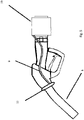
- the main device (10) according to the invention is externally connected to the filling elbow (12) preferably detachably and in a way positioned near the tank refilling line (13).
- a suction tube (9) may be arranged that will transmit the gaseous fuel form to be sampled to the sensor device within the main device (10).
- the fuel gas sample taken from the suction tube (9) will be detected by the sensor device as described above and compared with the data set pre-recorded in the controller memory or a mathematical modeling will be made, and the fuel type will be classified. If the fuel type present in the fuel truck is different from the fuel type in the tank, fuel transfer will not be permitted, otherwise it will. This permission may be provided for example by a solenoid valve at the fuel outlet of the tank keeping its closed position.
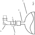
- Fig. 7 shows an alternative embodiment according to which the main device (10) is externally connected to the filling elbow (12), in this embodiment however, the filling elbow (12) may optionally be in fuel vapor communication with the main device (10) through a gap (16). Such communication may be provided by an optional valve (15).
- the valve (15) When the filling elbow (12) is placed on the filling cover of the tank, the valve (15) provides the transmission of the fuel vapor in gaseous form moving within the tank to the sensor device in the main device (10). On the other hand, when the fuel transfer is permitted, the valve (15) prevents the liquid fuel passing through the filling elbow (12) to leak into the main device (10).
- the apparatus according to the invention may also be configured as a component of a fuel vapor recovery system.
- a fuel vapor recovery system Such systems are known in the art and may generally be used in a fuel dispenser or fuel transfer between the fuel truck and the gas station tank.
- a fuel vapor recovery system basically comprises a vacuum pump sucking the vapor, a pressurized or non-pressurized condensation chamber for converting the suctioned vapor into liquid form and lines providing transport among the components.
- the apparatus according to the invention may be arranged on any part of the fuel vapor recovery system, such as the condensation chamber, the line, or in connection with an element that provides a link to the line.
- the fuel transfer control may be provided by a membraned sensor device.
- Fig. 8 shows an example for such a sensor device.
- the sensor device (11) defines a structure in substantially closed form containing a gas intake (19) and a gas outlet (20) preferably opposing each other. Inside said sensor device (11), there is an empty chamber divided into two sections through a membrane (21) to define a first chamber (25) and a second chamber (26).
- the gas intake (19) is configured at the side of the first chamber (25) and the gas outlet (20) is configured at the side of the second chamber (26).
- the configuration of the membrane (21) comprises a frame which preferably comprises micro-scale pores (22) of 0.10-0.50 ⁇ m and one or more polymer layers accumulated thereon.
- various materials may be used such as polysulfone (PS), PI, polyetherimide (PEI), polyvinylidene fluoride (PVDF) or sulfonated tetrafluoroethylene fluoropolymer-copolymer (Nafion ® ).
- polyether block amide PEBA
- PEG polyethylene glycol
- PI polyimide
- PU polyurethane
- PDMS polydimethylsiloxane
- cross-linking within the polymeric layer or interlayer cross-linking may be applied.
- Cross-linking may be enabled through agents such as maleic anhydride, glutaraldehyde, etc. and also by heat treatment.
- the selectivity and gas permeation rates of the membrane may be adjusted by using inorganic nano-fillers on polymer layers, such as graphene oxide or carbon nanotubes.
- the polymers in the quantity determined for the production of the membrane according to the invention may be dissolved by using appropriate solvents such as isopropanol/n-propanol, n-butanol or hexane. If it is aimed to use nano-fillers, then the selected inorganic material may be dispersed in this solution.
- the polymer-inorganic material mixture may be cast by using a membrane casting apparatus in order to prepare a microporous frame structure of the desired thickness.
- the accumulation process is performed on the selected microporous frame. Parameters such as the duration of the process, selection of the solvent medium, need for a catalyst and the solvent removal step may be determined depending on the frame and the polymer.
- the synthesized membranes may be subjected to various functionality tests such as mechanical and thermal resistance and gas permeability, thereby determining the selectivity values.
- the size of the pores (22) of the membrane (21) will permit fuel gas molecules of certain molecular size to permeate whereas larger molecules will not be permitted.
- Fig. 8 when diesel gas enters into the gas intake, since diesel molecules (23) will not permeate through the membrane pores (22), they will accumulate in the first chamber (25).
- diesel gas may not always wholly comprise diesel molecules and may also have smaller molecules, i.e. molecules of the size of gasoline molecules (21) even at small rates, a portion of which will permeate through the membrane pores (22) and accumulate in the second chamber (26). Accordingly, the membrane (21) will separate gas molecules of different sizes so that they can be kept in the first chamber (25) and the second chamber (26), respectively.
- the first chamber (25) is provided with a first gas sensor (17) and the second chamber (26) is provided with a second gas sensor (18).
- the first gas sensor (17) and the second gas sensor (18) may for example be a known VOC sensor or MEMS metal oxide sensor or air quality sensor or MEMS sensor.
- Said sensors (17, 18) communicate with a control unit. In practice, the signal received from the first gas sensor (17) (the signal related to the gas density level) and the signal received from the second gas sensor (18) (the signal related to the gas density level) are compared and interpreted by the control unit.
- the gas mixture entering into the sensor device (11) is a large-molecule gas mixture formed by the vaporization of diesel. For example, as shown in Fig. 9 , if there is a specific rate between the signal received from the first gas sensor (17) and the signal received from the second gas sensor (18) based on the predetermined tolerance range for gasoline vapor, then it may be decided that the gas mixture entering into the sensor device (11) is a gas mixture formed by the vaporization of gasoline.
- a suction fan may be arranged at the gas outlet (20) side, thereby enabling a more regular and rapid exit of the gas entering through the gas intake (19) from the sensor device (11) chamber.
- a suction fan may be arranged at the gas intake (19) side, thereby enabling a more regular and rapid introduction of the gas through the gas intake (19) inside the sensor device (11) chamber.
- the fan arranged at the gas intake (19) side may enable both a more regular and rapid introduction of the gas through the gas intake (19) inside the sensor device (11) chamber and also rapid discharge of the fuel vapor entering into the sensor device (11) chamber through the gas intake (19) again from the intake (19).
Landscapes
- Business, Economics & Management (AREA)
- Accounting & Taxation (AREA)
- Engineering & Computer Science (AREA)
- Finance (AREA)
- Mechanical Engineering (AREA)
- Physics & Mathematics (AREA)
- General Physics & Mathematics (AREA)
- Development Economics (AREA)
- Chemical & Material Sciences (AREA)
- Economics (AREA)
- Analytical Chemistry (AREA)
- Strategic Management (AREA)
- General Business, Economics & Management (AREA)
- Theoretical Computer Science (AREA)
- Investigating Or Analyzing Materials By The Use Of Electric Means (AREA)
- Combined Controls Of Internal Combustion Engines (AREA)
- Organic Low-Molecular-Weight Compounds And Preparation Thereof (AREA)
- Cooling, Air Intake And Gas Exhaust, And Fuel Tank Arrangements In Propulsion Units (AREA)
Claims (15)
- Ein Verfahren zum Steuern des Transfers eines Kraftstoffs eines bekannten Typs oder eines unbekannten Typs von einem ersten Ort zu einem zweiten Ort mit einem Kraftstoff eines bekannten Typs oder eines unbekannten Typs, das die folgenden Schritte beinhaltet:a. Bestimmen des unbekannten Kraftstofftyps an mindestens einem der Orte,b. Vergleichen des Kraftstofftyps an dem zweiten Ort mit dem Kraftstofftyp an dem ersten Ort,c. Ermöglichen des Kraftstofftransfers in dem Fall, dass der Kraftstofftyp an dem ersten Ort mit dem Kraftstofftyp an dem zweiten Ort übereinstimmt, und ansonsten Verhindern des Transfers,wobei die Bestimmung in dem Schritt a das Messen der Dichte und der Temperatur oder das Messen der Dichte und des Drucks einer gasförmigen Form des unbekannten Kraftstoffs an dem/den jeweiligen Ort(en) und das Vergleichen der gemessenen Werte mit einem Datensatz, der vorgegebene Bezugswerte beinhaltet, oder das Treffen einer Entscheidung mittels mathematischer Modellierung beinhaltet.
- Verfahren gemäß Anspruch 1, wobei der erste Ort eine Zapfsäule (7) ist und der zweite Ort der Kraftstofftank eines Landfahrzeugs ist.
- Verfahren gemäß Anspruch 1, wobei der erste Ort der Tank eines Tanklasters ist und der zweite Ort der Tank (14) einer Tankstelle ist.
- Verfahren gemäß Anspruch 1, wobei der Kraftstoff entweder an dem ersten Ort oder an dem zweiten Ort entweder Benzin oder Diesel ist.
- Verfahren gemäß Anspruch 1, wobei die Dichte der gasförmigen Form des Kraftstoffs durch einen Gassensor (1) gemessen wird, die Temperatur oder der Druck durch einen Zustandssensor (3) gemessen wird und die von den Sensoren empfangenen Daten durch eine Steuereinheit (2) verarbeitet werden, welche durch Vergleichen der Daten mit einem Datensatz, der vorgegebene Bezugswerte beinhaltet, oder mittels mathematischer Modellierung ein Befehlssignal erzeugt.
- Verfahren gemäß Anspruch 1, wobei, wenn die aus der Temperatur- oder Druckmessung erhaltenen Daten nicht mit dem Datensatz, der die vorgegebenen Bezugswerte beinhaltet, übereinstimmen oder als Ergebnis einer mathematischen Modellierung, die erhaltenen Daten aus einem vorbereiteten Datensatz geschätzt werden.
- Eine Vorrichtung zum Steuern des Transfers eines Typs von Kraftstoff von einem ersten Ort zu einem zweiten Ort, beinhaltend ein Sensorgerät (11) zum Detektieren des Typs des Kraftstoffs an einem der Orte und eine Steuereinheit (2), die mit dem Sensorgerät kommuniziert, wobei die Steuereinheit (2) konfiguriert ist, um die von dem Sensorgerät empfangenen Daten mit einem Datensatz, der vorgegebene Bezugswerte beinhaltet, zu vergleichen oder um eine mathematische Modellierung durchzuführen, dadurch gekennzeichnet, dass das Sensorgerät (11) einen Gassensor (1) zum Detektieren der Dichte der gasförmigen Form des Kraftstoffs an einem entsprechenden Ort und mindestens einen Gasform-Zustandssensor zum Detektieren der Temperatur oder des Drucks der gasförmigen Form des Kraftstoffs an einem entsprechenden Ort beinhaltet.
- Vorrichtung gemäß Anspruch 7, dadurch gekennzeichnet, dass die Sensorvorrichtung (11) eine Gasaufnahme (19), einen Gasauslass (20), eine erste Kammer (25), eine zweite Kammer (26), mindestens eine Membran (21), die zum Trennen der Kammern eingerichtet ist, mindestens einen ersten Gassensor (17), der mit der ersten Kammer (25) kommuniziert, und mindestens einen zweiten Gassensor (18), der mit der zweiten Kammer (26) kommuniziert, beinhaltet.
- Vorrichtung gemäß Anspruch 8, wobei die Membran (21) einen mikroporösen Rahmen und eine oder mehrere darauf abgelagerte Polymerschichten beinhaltet.
- Vorrichtung gemäß Anspruch 9, wobei der mikroporöse Rahmen aus der Gruppe ausgewählt ist, die aus Folgendem besteht: Polysulfon (PS), PI, Polyetherimid (PEI), Polyvinylidenfluorid (PVDF) und sulfoniertem Tetrafluorethylenfluorpolymer-Copolymer (Nafion®), und das Polymer aus der Gruppe ausgewählt ist, die aus Folgendem besteht: Polyetherblockamid (PEBA), Polyethylenglycol (PEG), Polyimid (PI), Polyurethan (PU) und Polydimethylsiloxan (PDMS).
- Vorrichtung gemäß Anspruch 10, wobei das Polymer Vernetzung durch ein Mittel, ausgewählt aus der Gruppe, bestehend aus Maleinsäureanhydrid und Glutaraldehyd, beinhaltet.
- Vorrichtung gemäß Anspruch 10, wobei das Polymer einen anorganischen Nanofüllstoff, ausgewählt aus der Gruppe, bestehend aus Graphenoxid und Kohlenstoffnanoröhrchen, beinhaltet.
- Vorrichtung gemäß Anspruch 8, wobei der mindestens eine erste Gassensor (17) und mindestens eine zweite Gassensor (18) aus der Gruppe ausgewählt sind, die aus Folgendem besteht: einem VOC-Sensor, einem MEMS-Metalloxidsensor, einem Luftqualitätssensor und einem MEMS-Sensor.
- Vorrichtung gemäß Anspruch 8, wobei die Vorrichtung mindestens ein Gebläse beinhaltet.
- Vorrichtung gemäß Anspruch 14, wobei die Vorrichtung mindestens ein Sauggebläse beinhaltet, das an der Seite der Gasaufnahme und/oder an der Seite des Gasauslasses bereitgestellt ist.
Priority Applications (1)
| Application Number | Priority Date | Filing Date | Title |
|---|---|---|---|
| EP22020144.6A EP4047365B1 (de) | 2018-04-13 | 2019-04-01 | Vorrichtung zur erkennung des kraftstofftyps zur kraftstoffübertragung |
Applications Claiming Priority (2)
| Application Number | Priority Date | Filing Date | Title |
|---|---|---|---|
| TR201805287 | 2018-04-13 | ||
| PCT/TR2019/000027 WO2019236032A2 (en) | 2018-04-13 | 2019-04-01 | Fuel type identification and transfer method and apparatus therefor |
Related Child Applications (2)
| Application Number | Title | Priority Date | Filing Date |
|---|---|---|---|
| EP22020144.6A Division-Into EP4047365B1 (de) | 2018-04-13 | 2019-04-01 | Vorrichtung zur erkennung des kraftstofftyps zur kraftstoffübertragung |
| EP22020144.6A Division EP4047365B1 (de) | 2018-04-13 | 2019-04-01 | Vorrichtung zur erkennung des kraftstofftyps zur kraftstoffübertragung |
Publications (3)
| Publication Number | Publication Date |
|---|---|
| EP3776503A2 EP3776503A2 (de) | 2021-02-17 |
| EP3776503A4 EP3776503A4 (de) | 2022-04-13 |
| EP3776503B1 true EP3776503B1 (de) | 2022-12-14 |
Family
ID=68770970
Family Applications (2)
| Application Number | Title | Priority Date | Filing Date |
|---|---|---|---|
| EP22020144.6A Active EP4047365B1 (de) | 2018-04-13 | 2019-04-01 | Vorrichtung zur erkennung des kraftstofftyps zur kraftstoffübertragung |
| EP19815001.3A Active EP3776503B1 (de) | 2018-04-13 | 2019-04-01 | Verfahren und vorrichtung zur identifizierung des kraftstofftyps und übertragung |
Family Applications Before (1)
| Application Number | Title | Priority Date | Filing Date |
|---|---|---|---|
| EP22020144.6A Active EP4047365B1 (de) | 2018-04-13 | 2019-04-01 | Vorrichtung zur erkennung des kraftstofftyps zur kraftstoffübertragung |
Country Status (2)
| Country | Link |
|---|---|
| EP (2) | EP4047365B1 (de) |
| WO (1) | WO2019236032A2 (de) |
Families Citing this family (13)
| Publication number | Priority date | Publication date | Assignee | Title |
|---|---|---|---|---|
| US11760170B2 (en) | 2020-08-20 | 2023-09-19 | Denso International America, Inc. | Olfaction sensor preservation systems and methods |
| US11813926B2 (en) | 2020-08-20 | 2023-11-14 | Denso International America, Inc. | Binding agent and olfaction sensor |
| US12251991B2 (en) | 2020-08-20 | 2025-03-18 | Denso International America, Inc. | Humidity control for olfaction sensors |
| US12017506B2 (en) | 2020-08-20 | 2024-06-25 | Denso International America, Inc. | Passenger cabin air control systems and methods |
| US11636870B2 (en) | 2020-08-20 | 2023-04-25 | Denso International America, Inc. | Smoking cessation systems and methods |
| US12377711B2 (en) | 2020-08-20 | 2025-08-05 | Denso International America, Inc. | Vehicle feature control systems and methods based on smoking |
| US11760169B2 (en) | 2020-08-20 | 2023-09-19 | Denso International America, Inc. | Particulate control systems and methods for olfaction sensors |
| US11881093B2 (en) | 2020-08-20 | 2024-01-23 | Denso International America, Inc. | Systems and methods for identifying smoking in vehicles |
| US12269315B2 (en) | 2020-08-20 | 2025-04-08 | Denso International America, Inc. | Systems and methods for measuring and managing odor brought into rental vehicles |
| US11828210B2 (en) | 2020-08-20 | 2023-11-28 | Denso International America, Inc. | Diagnostic systems and methods of vehicles using olfaction |
| US11932080B2 (en) | 2020-08-20 | 2024-03-19 | Denso International America, Inc. | Diagnostic and recirculation control systems and methods |
| US11673790B2 (en) * | 2021-06-15 | 2023-06-13 | Shell Retail And Convenience Operations Llc | Methods and systems for dispensing fuel |
| US12085216B2 (en) | 2022-02-17 | 2024-09-10 | Arctic Cat Inc. | Multi-use fuel filler tube |
Family Cites Families (10)
| Publication number | Priority date | Publication date | Assignee | Title |
|---|---|---|---|---|
| GB8612020D0 (en) | 1986-05-16 | 1986-06-25 | Shell Int Research | Misfuelling prevention device |
| US5209275A (en) | 1987-07-09 | 1993-05-11 | Junkosha Co., Ltd. | Liquid dispensing apparatus and method by sensing the type of liquid vapors in the receiver |
| JPH03111295A (ja) * | 1989-09-20 | 1991-05-13 | Tokico Ltd | 給油装置 |
| JPH04352697A (ja) * | 1991-05-20 | 1992-12-07 | Tokico Ltd | 給油装置 |
| EP0566345B1 (de) * | 1992-04-13 | 1995-12-13 | Tatsuno Corporation | Kraftstoffabgabegerät mit Vorrichtung zum Erkennen der Kraftstoffsorte |
| JP4278181B2 (ja) * | 1996-11-01 | 2009-06-10 | ビーピー オイル インターナショナル リミテッド | 検査装置と使用方法 |
| US6068030A (en) * | 1998-10-15 | 2000-05-30 | Tatsuno Corp. | Fueling system |
| US6712102B2 (en) * | 2002-05-07 | 2004-03-30 | Russell Shane Zerangue, Sr. | Method and system for preventing vehicle misfuelling |
| DE102011112417A1 (de) * | 2011-09-03 | 2013-03-07 | Hubert Rother | Schutzvorrichtung zur Verhinderung von Falschbetankungen und Prozedur zum Betrieb der Schutzvorrichtung |
| ES2629314T3 (es) * | 2012-11-14 | 2017-08-08 | Elaflex Hiby Tanktechnik Gmbh & Co. | Válvula de distribución con una válvula de seguridad |
-
2019
- 2019-04-01 EP EP22020144.6A patent/EP4047365B1/de active Active
- 2019-04-01 WO PCT/TR2019/000027 patent/WO2019236032A2/en not_active Ceased
- 2019-04-01 EP EP19815001.3A patent/EP3776503B1/de active Active
Also Published As
| Publication number | Publication date |
|---|---|
| WO2019236032A2 (en) | 2019-12-12 |
| EP3776503A4 (de) | 2022-04-13 |
| EP4047365B1 (de) | 2023-05-10 |
| WO2019236032A3 (en) | 2020-01-23 |
| EP4047365A1 (de) | 2022-08-24 |
| EP3776503A2 (de) | 2021-02-17 |
Similar Documents
| Publication | Publication Date | Title |
|---|---|---|
| EP3776503A2 (de) | Verfahren und vorrichtung zur identifizierung des kraftstofftyps und übertragung | |
| US8181631B2 (en) | Hydrocarbon storage canister purge system and method | |
| US10451010B2 (en) | Systems and methods for diagnosing components in a vehicle evaporative emissions system | |
| US10138846B1 (en) | Systems and methods for an evaporative emissions system and fuel system having a single delta pressure sensor | |
| US8935044B2 (en) | Refueling detection for diagnostic monitor | |
| EP3260373B1 (de) | Kraftstofftanksystem und -verfahren | |
| US20150019066A1 (en) | Leak detection for canister purge valve | |
| CN110030123A (zh) | 用于车辆燃料系统和蒸发排放系统诊断的系统和方法 | |
| CN109973232B (zh) | 用于车辆燃料系统和蒸发排放系统诊断的系统和方法 | |
| CN109595102B (zh) | 用于具有单个δ压力传感器的蒸发排放系统和燃料系统的系统和方法 | |
| US10611625B2 (en) | Systems and methods for detection of vehicle misfueling | |
| US11274622B1 (en) | Methods and systems for diagnosing fuel system degradation | |
| US6158270A (en) | Method and apparatus for detecting vapor leakage | |
| US20140109882A1 (en) | Method for monitoring the leak tightness of a fuel tank system | |
| US20170260930A1 (en) | Leakage Diagnosis In A Fuel Tank System | |
| KR20160042419A (ko) | 차량 연료 저장 시스템을 감압하기 위한 방법 및 시스템 | |
| US20150046026A1 (en) | Engine-off leak detection based on pressure | |
| CN116576045A (zh) | 用于重型车辆中的蒸发排放控制系统的滤罐容量诊断 | |
| CN117162767A (zh) | 用于无压力燃料箱的方法和系统 | |
| EP3409936A1 (de) | Verfahren und system zur bestimmung eines lecks in einem druckbeaufschlagten brennstoffsystem | |
| CN111060361B (zh) | 一种燃油系统检测装置及其检测方法 | |
| US11651631B2 (en) | Methods and systems for diagnosing degradation in pressureless fuel tank | |
| US11118958B2 (en) | System for determining a filling level in a fuel tank | |
| US12606014B2 (en) | Methods and systems for a pressureless fuel tank | |
| US12601316B2 (en) | Method and device for diagnosing a leak in an evaporation system and in a tank ventilation line of an internal combustion engine |
Legal Events
| Date | Code | Title | Description |
|---|---|---|---|
| STAA | Information on the status of an ep patent application or granted ep patent |
Free format text: STATUS: THE INTERNATIONAL PUBLICATION HAS BEEN MADE |
|
| TPAC | Observations filed by third parties |
Free format text: ORIGINAL CODE: EPIDOSNTIPA |
|
| PUAI | Public reference made under article 153(3) epc to a published international application that has entered the european phase |
Free format text: ORIGINAL CODE: 0009012 |
|
| STAA | Information on the status of an ep patent application or granted ep patent |
Free format text: STATUS: REQUEST FOR EXAMINATION WAS MADE |
|
| 17P | Request for examination filed |
Effective date: 20201102 |
|
| AK | Designated contracting states |
Kind code of ref document: A2 Designated state(s): AL AT BE BG CH CY CZ DE DK EE ES FI FR GB GR HR HU IE IS IT LI LT LU LV MC MK MT NL NO PL PT RO RS SE SI SK SM TR |
|
| AX | Request for extension of the european patent |
Extension state: BA ME |
|
| DAV | Request for validation of the european patent (deleted) | ||
| DAX | Request for extension of the european patent (deleted) | ||
| RIC1 | Information provided on ipc code assigned before grant |
Ipc: B67D 7/42 20100101ALI20211207BHEP Ipc: B67D 7/04 20100101ALI20211207BHEP Ipc: B60S 5/02 20060101ALI20211207BHEP Ipc: G01N 33/28 20060101ALI20211207BHEP Ipc: G08B 13/00 20060101AFI20211207BHEP |
|
| A4 | Supplementary search report drawn up and despatched |
Effective date: 20220316 |
|
| RIC1 | Information provided on ipc code assigned before grant |
Ipc: B67D 7/42 20100101ALI20220310BHEP Ipc: B67D 7/04 20100101ALI20220310BHEP Ipc: B60S 5/02 20060101ALI20220310BHEP Ipc: G01N 33/28 20060101ALI20220310BHEP Ipc: G08B 13/00 20060101AFI20220310BHEP |
|
| GRAP | Despatch of communication of intention to grant a patent |
Free format text: ORIGINAL CODE: EPIDOSNIGR1 |
|
| STAA | Information on the status of an ep patent application or granted ep patent |
Free format text: STATUS: GRANT OF PATENT IS INTENDED |
|
| INTG | Intention to grant announced |
Effective date: 20220901 |
|
| GRAS | Grant fee paid |
Free format text: ORIGINAL CODE: EPIDOSNIGR3 |
|
| GRAA | (expected) grant |
Free format text: ORIGINAL CODE: 0009210 |
|
| STAA | Information on the status of an ep patent application or granted ep patent |
Free format text: STATUS: THE PATENT HAS BEEN GRANTED |
|
| AK | Designated contracting states |
Kind code of ref document: B1 Designated state(s): AL AT BE BG CH CY CZ DE DK EE ES FI FR GB GR HR HU IE IS IT LI LT LU LV MC MK MT NL NO PL PT RO RS SE SI SK SM TR |
|
| REG | Reference to a national code |
Ref country code: GB Ref legal event code: FG4D |
|
| REG | Reference to a national code |
Ref country code: CH Ref legal event code: EP |
|
| REG | Reference to a national code |
Ref country code: DE Ref legal event code: R096 Ref document number: 602019023237 Country of ref document: DE |
|
| REG | Reference to a national code |
Ref country code: IE Ref legal event code: FG4D |
|
| REG | Reference to a national code |
Ref country code: AT Ref legal event code: REF Ref document number: 1538150 Country of ref document: AT Kind code of ref document: T Effective date: 20230115 |
|
| REG | Reference to a national code |
Ref country code: LT Ref legal event code: MG9D |
|
| REG | Reference to a national code |
Ref country code: NL Ref legal event code: MP Effective date: 20221214 |
|
| PG25 | Lapsed in a contracting state [announced via postgrant information from national office to epo] |
Ref country code: SE Free format text: LAPSE BECAUSE OF FAILURE TO SUBMIT A TRANSLATION OF THE DESCRIPTION OR TO PAY THE FEE WITHIN THE PRESCRIBED TIME-LIMIT Effective date: 20221214 Ref country code: NO Free format text: LAPSE BECAUSE OF FAILURE TO SUBMIT A TRANSLATION OF THE DESCRIPTION OR TO PAY THE FEE WITHIN THE PRESCRIBED TIME-LIMIT Effective date: 20230314 Ref country code: LT Free format text: LAPSE BECAUSE OF FAILURE TO SUBMIT A TRANSLATION OF THE DESCRIPTION OR TO PAY THE FEE WITHIN THE PRESCRIBED TIME-LIMIT Effective date: 20221214 Ref country code: FI Free format text: LAPSE BECAUSE OF FAILURE TO SUBMIT A TRANSLATION OF THE DESCRIPTION OR TO PAY THE FEE WITHIN THE PRESCRIBED TIME-LIMIT Effective date: 20221214 |
|
| REG | Reference to a national code |
Ref country code: AT Ref legal event code: MK05 Ref document number: 1538150 Country of ref document: AT Kind code of ref document: T Effective date: 20221214 |
|
| PG25 | Lapsed in a contracting state [announced via postgrant information from national office to epo] |
Ref country code: RS Free format text: LAPSE BECAUSE OF FAILURE TO SUBMIT A TRANSLATION OF THE DESCRIPTION OR TO PAY THE FEE WITHIN THE PRESCRIBED TIME-LIMIT Effective date: 20221214 Ref country code: LV Free format text: LAPSE BECAUSE OF FAILURE TO SUBMIT A TRANSLATION OF THE DESCRIPTION OR TO PAY THE FEE WITHIN THE PRESCRIBED TIME-LIMIT Effective date: 20221214 Ref country code: HR Free format text: LAPSE BECAUSE OF FAILURE TO SUBMIT A TRANSLATION OF THE DESCRIPTION OR TO PAY THE FEE WITHIN THE PRESCRIBED TIME-LIMIT Effective date: 20221214 Ref country code: GR Free format text: LAPSE BECAUSE OF FAILURE TO SUBMIT A TRANSLATION OF THE DESCRIPTION OR TO PAY THE FEE WITHIN THE PRESCRIBED TIME-LIMIT Effective date: 20230315 |
|
| PG25 | Lapsed in a contracting state [announced via postgrant information from national office to epo] |
Ref country code: NL Free format text: LAPSE BECAUSE OF FAILURE TO SUBMIT A TRANSLATION OF THE DESCRIPTION OR TO PAY THE FEE WITHIN THE PRESCRIBED TIME-LIMIT Effective date: 20221214 |
|
| PG25 | Lapsed in a contracting state [announced via postgrant information from national office to epo] |
Ref country code: SM Free format text: LAPSE BECAUSE OF FAILURE TO SUBMIT A TRANSLATION OF THE DESCRIPTION OR TO PAY THE FEE WITHIN THE PRESCRIBED TIME-LIMIT Effective date: 20221214 Ref country code: RO Free format text: LAPSE BECAUSE OF FAILURE TO SUBMIT A TRANSLATION OF THE DESCRIPTION OR TO PAY THE FEE WITHIN THE PRESCRIBED TIME-LIMIT Effective date: 20221214 Ref country code: PT Free format text: LAPSE BECAUSE OF FAILURE TO SUBMIT A TRANSLATION OF THE DESCRIPTION OR TO PAY THE FEE WITHIN THE PRESCRIBED TIME-LIMIT Effective date: 20230414 Ref country code: ES Free format text: LAPSE BECAUSE OF FAILURE TO SUBMIT A TRANSLATION OF THE DESCRIPTION OR TO PAY THE FEE WITHIN THE PRESCRIBED TIME-LIMIT Effective date: 20221214 Ref country code: EE Free format text: LAPSE BECAUSE OF FAILURE TO SUBMIT A TRANSLATION OF THE DESCRIPTION OR TO PAY THE FEE WITHIN THE PRESCRIBED TIME-LIMIT Effective date: 20221214 Ref country code: CZ Free format text: LAPSE BECAUSE OF FAILURE TO SUBMIT A TRANSLATION OF THE DESCRIPTION OR TO PAY THE FEE WITHIN THE PRESCRIBED TIME-LIMIT Effective date: 20221214 Ref country code: AT Free format text: LAPSE BECAUSE OF FAILURE TO SUBMIT A TRANSLATION OF THE DESCRIPTION OR TO PAY THE FEE WITHIN THE PRESCRIBED TIME-LIMIT Effective date: 20221214 |
|
| PGFP | Annual fee paid to national office [announced via postgrant information from national office to epo] |
Ref country code: IT Payment date: 20230418 Year of fee payment: 5 |
|
| PG25 | Lapsed in a contracting state [announced via postgrant information from national office to epo] |
Ref country code: SK Free format text: LAPSE BECAUSE OF FAILURE TO SUBMIT A TRANSLATION OF THE DESCRIPTION OR TO PAY THE FEE WITHIN THE PRESCRIBED TIME-LIMIT Effective date: 20221214 Ref country code: PL Free format text: LAPSE BECAUSE OF FAILURE TO SUBMIT A TRANSLATION OF THE DESCRIPTION OR TO PAY THE FEE WITHIN THE PRESCRIBED TIME-LIMIT Effective date: 20221214 Ref country code: IS Free format text: LAPSE BECAUSE OF FAILURE TO SUBMIT A TRANSLATION OF THE DESCRIPTION OR TO PAY THE FEE WITHIN THE PRESCRIBED TIME-LIMIT Effective date: 20230414 Ref country code: AL Free format text: LAPSE BECAUSE OF FAILURE TO SUBMIT A TRANSLATION OF THE DESCRIPTION OR TO PAY THE FEE WITHIN THE PRESCRIBED TIME-LIMIT Effective date: 20221214 |
|
| REG | Reference to a national code |
Ref country code: DE Ref legal event code: R097 Ref document number: 602019023237 Country of ref document: DE |
|
| PLBE | No opposition filed within time limit |
Free format text: ORIGINAL CODE: 0009261 |
|
| STAA | Information on the status of an ep patent application or granted ep patent |
Free format text: STATUS: NO OPPOSITION FILED WITHIN TIME LIMIT |
|
| PG25 | Lapsed in a contracting state [announced via postgrant information from national office to epo] |
Ref country code: DK Free format text: LAPSE BECAUSE OF FAILURE TO SUBMIT A TRANSLATION OF THE DESCRIPTION OR TO PAY THE FEE WITHIN THE PRESCRIBED TIME-LIMIT Effective date: 20221214 |
|
| REG | Reference to a national code |
Ref country code: DE Ref legal event code: R119 Ref document number: 602019023237 Country of ref document: DE |
|
| 26N | No opposition filed |
Effective date: 20230915 |
|
| PG25 | Lapsed in a contracting state [announced via postgrant information from national office to epo] |
Ref country code: SI Free format text: LAPSE BECAUSE OF FAILURE TO SUBMIT A TRANSLATION OF THE DESCRIPTION OR TO PAY THE FEE WITHIN THE PRESCRIBED TIME-LIMIT Effective date: 20221214 |
|
| REG | Reference to a national code |
Ref country code: CH Ref legal event code: PL |
|
| PG25 | Lapsed in a contracting state [announced via postgrant information from national office to epo] |
Ref country code: LU Free format text: LAPSE BECAUSE OF NON-PAYMENT OF DUE FEES Effective date: 20230401 |
|
| REG | Reference to a national code |
Ref country code: BE Ref legal event code: MM Effective date: 20230430 |
|
| PG25 | Lapsed in a contracting state [announced via postgrant information from national office to epo] |
Ref country code: MC Free format text: LAPSE BECAUSE OF FAILURE TO SUBMIT A TRANSLATION OF THE DESCRIPTION OR TO PAY THE FEE WITHIN THE PRESCRIBED TIME-LIMIT Effective date: 20221214 |
|
| PG25 | Lapsed in a contracting state [announced via postgrant information from national office to epo] |
Ref country code: MC Free format text: LAPSE BECAUSE OF FAILURE TO SUBMIT A TRANSLATION OF THE DESCRIPTION OR TO PAY THE FEE WITHIN THE PRESCRIBED TIME-LIMIT Effective date: 20221214 Ref country code: LI Free format text: LAPSE BECAUSE OF NON-PAYMENT OF DUE FEES Effective date: 20230430 Ref country code: FR Free format text: LAPSE BECAUSE OF NON-PAYMENT OF DUE FEES Effective date: 20230430 Ref country code: DE Free format text: LAPSE BECAUSE OF NON-PAYMENT OF DUE FEES Effective date: 20231103 Ref country code: CH Free format text: LAPSE BECAUSE OF NON-PAYMENT OF DUE FEES Effective date: 20230430 |
|
| REG | Reference to a national code |
Ref country code: IE Ref legal event code: MM4A |
|
| PG25 | Lapsed in a contracting state [announced via postgrant information from national office to epo] |
Ref country code: BE Free format text: LAPSE BECAUSE OF NON-PAYMENT OF DUE FEES Effective date: 20230430 |
|
| PG25 | Lapsed in a contracting state [announced via postgrant information from national office to epo] |
Ref country code: IE Free format text: LAPSE BECAUSE OF NON-PAYMENT OF DUE FEES Effective date: 20230401 |
|
| PG25 | Lapsed in a contracting state [announced via postgrant information from national office to epo] |
Ref country code: IE Free format text: LAPSE BECAUSE OF NON-PAYMENT OF DUE FEES Effective date: 20230401 |
|
| PGFP | Annual fee paid to national office [announced via postgrant information from national office to epo] |
Ref country code: GB Payment date: 20240419 Year of fee payment: 6 |
|
| PG25 | Lapsed in a contracting state [announced via postgrant information from national office to epo] |
Ref country code: BG Free format text: LAPSE BECAUSE OF FAILURE TO SUBMIT A TRANSLATION OF THE DESCRIPTION OR TO PAY THE FEE WITHIN THE PRESCRIBED TIME-LIMIT Effective date: 20221214 |
|
| PG25 | Lapsed in a contracting state [announced via postgrant information from national office to epo] |
Ref country code: BG Free format text: LAPSE BECAUSE OF FAILURE TO SUBMIT A TRANSLATION OF THE DESCRIPTION OR TO PAY THE FEE WITHIN THE PRESCRIBED TIME-LIMIT Effective date: 20221214 |
|
| PG25 | Lapsed in a contracting state [announced via postgrant information from national office to epo] |
Ref country code: IT Free format text: LAPSE BECAUSE OF NON-PAYMENT OF DUE FEES Effective date: 20240401 |
|
| PG25 | Lapsed in a contracting state [announced via postgrant information from national office to epo] |
Ref country code: CY Free format text: LAPSE BECAUSE OF FAILURE TO SUBMIT A TRANSLATION OF THE DESCRIPTION OR TO PAY THE FEE WITHIN THE PRESCRIBED TIME-LIMIT; INVALID AB INITIO Effective date: 20190401 |
|
| PG25 | Lapsed in a contracting state [announced via postgrant information from national office to epo] |
Ref country code: HU Free format text: LAPSE BECAUSE OF FAILURE TO SUBMIT A TRANSLATION OF THE DESCRIPTION OR TO PAY THE FEE WITHIN THE PRESCRIBED TIME-LIMIT; INVALID AB INITIO Effective date: 20190401 |
|
| GBPC | Gb: european patent ceased through non-payment of renewal fee |
Effective date: 20250401 |
|
| PG25 | Lapsed in a contracting state [announced via postgrant information from national office to epo] |
Ref country code: GB Free format text: LAPSE BECAUSE OF NON-PAYMENT OF DUE FEES Effective date: 20250401 |
|
| PGFP | Annual fee paid to national office [announced via postgrant information from national office to epo] |
Ref country code: TR Payment date: 20260318 Year of fee payment: 8 |