EP3776603B1 - Varistance protégée thermiquement - Google Patents
Varistance protégée thermiquement Download PDFInfo
- Publication number
- EP3776603B1 EP3776603B1 EP19716131.8A EP19716131A EP3776603B1 EP 3776603 B1 EP3776603 B1 EP 3776603B1 EP 19716131 A EP19716131 A EP 19716131A EP 3776603 B1 EP3776603 B1 EP 3776603B1
- Authority
- EP
- European Patent Office
- Prior art keywords
- protection device
- thermal protection
- varistor
- contact surface
- housing
- Prior art date
- Legal status (The legal status is an assumption and is not a legal conclusion. Google has not performed a legal analysis and makes no representation as to the accuracy of the status listed.)
- Active
Links
Images


Classifications
-
- H—ELECTRICITY
- H01—ELECTRIC ELEMENTS
- H01C—RESISTORS
- H01C1/00—Details
- H01C1/08—Cooling, heating or ventilating arrangements
-
- H—ELECTRICITY
- H01—ELECTRIC ELEMENTS
- H01C—RESISTORS
- H01C1/00—Details
- H01C1/14—Terminals or tapping points specially adapted for resistors; Arrangements of terminals or tapping points on resistors
- H01C1/144—Terminals or tapping points specially adapted for resistors; Arrangements of terminals or tapping points on resistors the terminals or tapping points being welded or soldered
-
- H—ELECTRICITY
- H01—ELECTRIC ELEMENTS
- H01C—RESISTORS
- H01C7/00—Non-adjustable resistors formed as one or more layers or coatings; Non-adjustable resistors made from powdered conducting material or powdered semi-conducting material with or without insulating material
- H01C7/10—Non-adjustable resistors formed as one or more layers or coatings; Non-adjustable resistors made from powdered conducting material or powdered semi-conducting material with or without insulating material voltage responsive, i.e. varistors
- H01C7/12—Overvoltage protection resistors; Arresters
- H01C7/126—Means for protecting against excessive pressure or for disconnecting in case of failure
-
- H—ELECTRICITY
- H01—ELECTRIC ELEMENTS
- H01H—ELECTRIC SWITCHES; RELAYS; SELECTORS; EMERGENCY PROTECTIVE DEVICES
- H01H37/00—Thermally-actuated switches
- H01H37/74—Switches in which only the opening movement or only the closing movement of a contact is effected by heating or cooling
- H01H37/76—Contact member actuated by melting of fusible material, actuated due to burning of combustible material or due to explosion of explosive material
- H01H37/761—Contact member actuated by melting of fusible material, actuated due to burning of combustible material or due to explosion of explosive material with a fusible element forming part of the switched circuit
-
- H—ELECTRICITY
- H01—ELECTRIC ELEMENTS
- H01H—ELECTRIC SWITCHES; RELAYS; SELECTORS; EMERGENCY PROTECTIVE DEVICES
- H01H9/00—Details of switching devices, not covered by groups H01H1/00 - H01H7/00
- H01H9/0066—Auxiliary contact devices
-
- H—ELECTRICITY
- H01—ELECTRIC ELEMENTS
- H01H—ELECTRIC SWITCHES; RELAYS; SELECTORS; EMERGENCY PROTECTIVE DEVICES
- H01H9/00—Details of switching devices, not covered by groups H01H1/00 - H01H7/00
- H01H9/30—Means for extinguishing or preventing arc between current-carrying parts
- H01H9/32—Insulating body insertable between contacts
-
- H—ELECTRICITY
- H01—ELECTRIC ELEMENTS
- H01H—ELECTRIC SWITCHES; RELAYS; SELECTORS; EMERGENCY PROTECTIVE DEVICES
- H01H37/00—Thermally-actuated switches
- H01H37/74—Switches in which only the opening movement or only the closing movement of a contact is effected by heating or cooling
- H01H37/76—Contact member actuated by melting of fusible material, actuated due to burning of combustible material or due to explosion of explosive material
- H01H37/761—Contact member actuated by melting of fusible material, actuated due to burning of combustible material or due to explosion of explosive material with a fusible element forming part of the switched circuit
- H01H2037/762—Contact member actuated by melting of fusible material, actuated due to burning of combustible material or due to explosion of explosive material with a fusible element forming part of the switched circuit using a spring for opening the circuit when the fusible element melts
- H01H2037/763—Contact member actuated by melting of fusible material, actuated due to burning of combustible material or due to explosion of explosive material with a fusible element forming part of the switched circuit using a spring for opening the circuit when the fusible element melts the spring being a blade spring
-
- H—ELECTRICITY
- H01—ELECTRIC ELEMENTS
- H01H—ELECTRIC SWITCHES; RELAYS; SELECTORS; EMERGENCY PROTECTIVE DEVICES
- H01H9/00—Details of switching devices, not covered by groups H01H1/00 - H01H7/00
- H01H9/16—Indicators for switching condition, e.g. "on" or "off"
-
- H—ELECTRICITY
- H01—ELECTRIC ELEMENTS
- H01T—SPARK GAPS; OVERVOLTAGE ARRESTERS USING SPARK GAPS; SPARKING PLUGS; CORONA DEVICES; GENERATING IONS TO BE INTRODUCED INTO NON-ENCLOSED GASES
- H01T1/00—Details of spark gaps
- H01T1/12—Means structurally associated with spark gap for recording operation thereof
-
- H—ELECTRICITY
- H01—ELECTRIC ELEMENTS
- H01T—SPARK GAPS; OVERVOLTAGE ARRESTERS USING SPARK GAPS; SPARKING PLUGS; CORONA DEVICES; GENERATING IONS TO BE INTRODUCED INTO NON-ENCLOSED GASES
- H01T1/00—Details of spark gaps
- H01T1/14—Means structurally associated with spark gap for protecting it against overload or for disconnecting it in case of failure
Definitions
- the invention concerns a thermal protection device to protect a varistor against overheating.
- a varistor has a special current-voltage characteristic.
- the varistor changes from an electrically insulating state to an electrically conductive state if an applied voltage exceeds a certain value. This effect is used to protect voltage-sensitive electrical elements.
- the varistor becomes conductive, a high current can flow through it. The current can heat up the varistor to a point of explosion or other damage.
- thermal protection As described in US 6,430,019 B1 .
- One type of such protection is a thermal fuse.
- Other prior art is disclosed in documents WO2017/140463A1 , US2017/110279A1 , WO2017/139912A1 , KR200462103Y1 and EP2537164A2 .
- the task is a thermal protection device to protect a varistor in cases of overheating due to a persistently high voltage applied to the varistor for a certain time.
- the spring terminal would not revert to its initial position of connection to the first contact surface of the varistor without an external force after triggering of the thermal protection device.
- a part of the spring terminal can protrude from the housing. This part can be designed as a pluggable terminal. Therefore, it can provide a stably plugged thermal protection device.
- the connection between the spring terminal and the first contact surface of the varistor is implemented as a low temperature solder joint during the operational state of the thermal protection device.
- low temperature can be a characteristic temperature at which the solder joint would reach a state where it would allow a separation of the before-connected metal contact and the contact surface due to a force or pre-stress as it could exist in the metal contact. It is possible that the "low temperature” is the melting temperature of the low temperature solder. This characteristic temperature would be called “low” because of its possibly lower value compared to a usual characteristic temperature of solder.
- the characteristic temperature of the low temperature solder can be in a range from 100°C to 210°C, e.g. 138°C.
- fault is chosen due to the origin of the state, which is a fault in the system in which the thermal protection device is installed.
- heating of the low temperature solder joint can be caused either by a high current which flows through the connection as a consequence of the fault in the system or by the heat radiated from the varistor itself since the solder joint is in direct contact with the varistor. Additionally, the heating of the low temperature solder joint can be caused by any other source from outside the thermal protection device. A high current or a heated varistor are the cases against which the thermal protection device should protect the varistor. The arrangement of the low temperature solder joint can ensure a short response time of the thermal protection device.
- a possible combination of an embodiment with a low temperature solder joint with the spring terminal from the embodiment above can lead to a safe and fast disconnection of the first contact surface of the varistor, due to the arrangement of the connection close to the varistor and the stress in the connected spring terminal.
- the housing is closed by a removable plastic cap.
- the removable plastic cap would allow access to the parts in the cavity of the housing. Furthermore, with an accurate application of heat it can be possible to rebuild the low temperature solder joint between the spring terminal and the first contact surface after triggering of the thermal protection device. This would allow a skilled person to reset the thermal protection device to an operational state.
- thermal protection device comprises a spring in the cavity of the housing.
- the spring can be a torsion spring.
- the spring can be arranged adjacent to the inner wall of the housing opposite to the varistor.
- the thermal protection device of this embodiment can comprise a moveable insulation block inside the cavity of the housing adjacent to the inner wall.
- the moveable insulation block can be partly located between the spring terminal and the inner wall.
- Both the spring and the moveable insulation block or only one of them can have a common centre of rotation. At this centre of rotation a rivet would be arranged on the inner wall that reaches in the cavity of the housing. On the rivet both the spring and the moveable insulation block can be fixated.
- the spring can push the moveable insulation block against the spring terminal, which is connected to the first contact surface of the varistor.
- the moveable insulation block pushed by the spring can represent a source of force acting on the connection between the spring terminal and the first contact surface of the varistor, wherein the force performed by the spring and the moveable insulation block would be directed parallel to the inner wall.
- the force can be directed to separate the spring terminal from the first contact surface of the varistor in a fault state of the thermal protection device.
- the moveable insulation block in combination with the described spring force represents a further separation mechanism.
- Such a further separation mechanism in the form of the moveable insulation block pushed by a spring would increase the safety of the thermal protection device since it ensures a separation of the connection to the first contact surface if the connection gets loose.
- the moveable insulation block can be designed to move in a rotation around a rivet in the centre of rotation, no guide rails are needed. Therefore it is unlikely for the moveable insulation block to jam. This would improve the safety of the thermal protection device.
- the moveable insulation block as described above can be pushed in an end position by the spring in the case of a fault state of the thermal protection device.
- a fault state can be reached if the connection to the first contact surface of the varistor becomes loose due to a heating up of the varistor.
- the moveable insulation block can be designed to separate a terminal from the first contact surface of the varistor. Furthermore it can be designed to cover the window in the inner wall of the housing, as a result of which the first contact surface of the varistor would be completely electrically insulated and therefore defy electric arcs. Such a design would ensure the disconnection of the varistor and prevent an emergency of a flashover in a fault state of the thermal protection device.
- a possible embodiment of the thermal protection device comprises an indicator to signal the current state of the thermal protection device.
- the indicator would be partly arranged in the housing and can comprise signal contacts which protrude from the housing and an indicator trigger which is arranged in the housing.
- the indicator may be a micro-switch. It is also possible that the moveable insulation block reaches the trigger of the indicator in a fault state of the thermal protection device.
- the moveable insulation block can be designed to trigger the indicator if it is pushed in the end position of the moveable insulation block. It is possible that any further electronic be connected to the signal contacts of the indicator to display the state of the thermal protection device.
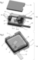
- FIG. 1 shows an exemplary embodiment of a thermal protection device 100 in an operational state.
- a housing 1 is represented as transparent to bring a varistor 2 into view, which is partly embedded in the housing 1.
- the housing 1 comprises an inner wall 16, which is arranged parallel to a contact surface 21 of the varistor 2.
- the housing defines at least one cavity.
- the inner wall 16 can also be a wall of the cavity mentioned before.
- the inner wall 16 comprises a window 12, which offers the possibility for forming a connection from a part in the cavity to the contact surface 21 of the varistor 2.
- the varistor 2 comprises a terminal 22. Said terminal is arranged on an opposite side of the contact surface 21 and protrudes from the housing 1.
- the thermal protection device 100 comprises a spring terminal 13, which is partly arranged in the cavity of the housing 1.
- the spring terminal is held in its position by a fixation feature 14 in the housing 1.
- the protruding parts of the spring terminal 13 and of the terminal 22 of the varistor 2 is designed to make the thermal protection device pluggable.
- an end of the spring terminal 13 in the cavity of the housing 1 is connected to the contact surface 21 of the varistor 2 through the window 12 in the inner wall 16 of the housing 1.
- the connection between the spring terminal 13 and the first contact surface causes a stress in the spring terminal, which is directed away from the contact surface 21 of the varistor 2.
- an electrical connection 11 is used.
- the electrical connection 11 is realised by a low temperature solder joint.
- Such a low temperature solder joint has a critical temperature at which the solder becomes liquid.
- the critical temperature at which the solder becomes liquid can be in a range between 100°C and 210°C, e.g. 138°C.
- the shown embodiment of the thermal protection device 100 in an operational state comprises a moveable insulation block 43, which is arranged in the cavity of the housing 1 and abuts on the inner wall 16.
- a spring 42 is placed in the cavity and pushes the moveable insulation block 43 against the spring terminal 13 near the electrical connection 11.
- the spring 42 is held in place by a feature to fix the spring 41, which is arranged on the inner wall 16 and reaches into the cavity of the housing 1.
- the path of movement for the moveable insulation block 43 and the spring 42 is a path of gyration with its centre at the feature 41 to fix the spring 42, in a plane parallel to the inner wall 16 and therefore parallel to the contact surface 21 of the varistor 2.
- the housing 1 there is a feature 3 to fix the indicator 31.
- This feature 3 is a notch in the outer wall of the housing, which reaches from an upper boundary of the housing to the level of the inner wall 16.
- the housing 1 comprises the feature 14 to fixate a spring terminal.
- the feature 14 also is a notch in the outer wall of the housing 1.
- the electrical connection 11 becomes loose either due to the stress in the spring terminal, which bends the spring terminal 13 away from the contact surface 21 of the varistor 2, or due to the torque of the spring 42, which pushes the moveable insulation block 43 between the spring terminal 13 and the inner wall 16, over the window 12.
- the spring terminal 13 is separated from the varistor 2 and the moveable insulation block closes the window 12 in the inner wall and activates the trigger 33 of the indicator 31.
- FIG. 5 shows an exemplary embodiment of the varistor 2.
- the varistor comprises the contact surface 21 on one side of the varistor 2.
- the contact surface 21 is arranged on a metallization layer 23 of the varistor 2.
- This metallization layer 23 can partly or completely extend over one side of the varistor 2.
- the varistor 2 comprises a further contact surface with the terminal 22 on the opposite side with respect to the contact surface 21.
- the terminal 22 of the varistor 2 protrudes over the dimensions of the varistor 2.
- the terminal 22 is designed in such a way that it reaches out of the housing 1.
- the varistor can be designed as a metal-oxide varistor.
- Such a metal-oxide varistor has a characteristic electrical behaviour if a voltage is applied between the two contact surfaces. If the applied voltage reaches a certain value, the varistor resistance changes rapidly from an insulating state to a conductive state.
Landscapes
- Engineering & Computer Science (AREA)
- Microelectronics & Electronic Packaging (AREA)
- Physics & Mathematics (AREA)
- Electromagnetism (AREA)
- Chemical & Material Sciences (AREA)
- Combustion & Propulsion (AREA)
- Fuses (AREA)
- Thermistors And Varistors (AREA)
Claims (11)
- Dispositif de protection thermique (100), comprenant- un logement (1),- une varistance (2) qui est partiellement incorporée dans le logement (1) pour isoler électriquement la varistance (2), la varistance (2) comprenant une surface de contact partiellement non isolée (21),- une paroi interne (16) de matériau isolant, qui est agencée de manière adjacente à la surface de contact (21) de la varistance (2)- une fenêtre (12) dans la paroi interne (16) pour permettre une connexion électrique (11) de la surface de contact (21) de la varistance (2) dans un état fonctionnel du dispositif de protection thermique (100),- un bloc d'isolation mobile (43) qui est agencé pour couvrir la fenêtre (12) dans la paroi interne (16) afin d'isoler la varistance (2) dans une région de la fenêtre (12) de la paroi interne (16) dans un état de panne du dispositif de protection thermique (100), dans lequel un contact métallique définit une borne à ressort (13), de telle sorte que la borne à ressort (13) soit électriquement connectée (11) à travers la fenêtre (12) à la surface de contact (21) de la varistance (2) pendant un état fonctionnel du dispositif de protection thermique (100).
- Dispositif de protection thermique (100) selon la revendication 1, dans lequel le contact métallique est soumis à une précontrainte agissant dans une direction s'éloignant de la surface de contact pendant un état fonctionnel du dispositif de protection thermique (100).
- Dispositif de protection thermique (100) selon la revendication 1 ou la revendication 2, dans lequel la connexion électrique (11) entre la surface de contact (21) de la varistance (2) et la borne à ressort (13) comprend un joint de soudure à basse température pendant un état fonctionnel du dispositif de protection thermique (100), la basse température étant une température caractéristique à laquelle le joint de soudure atteint un état où il permet à la précontrainte d'interrompre le contact avec la surface de contact.
- Dispositif de protection thermique (100) selon la revendication 3, dans lequel la température caractéristique est la température de fusion de la soudure, qui est comprise dans une plage de 180 °C à 210 °C, par ex. 200 °C.
- Dispositif de protection thermique (100) selon la revendication 1, la revendication 2, la revendication 3 ou la revendication 4, dans lequel le bloc d'isolation mobile (43) est pressé contre la borne à ressort (13) par une force de ressort provenant d'un ressort (42) pendant un état fonctionnel du dispositif de protection thermique (100).
- Dispositif de protection thermique (100) selon l'une des revendications précédentes, dans lequel le bloc d'isolation mobile (43) est conçu pour être poussé dans une position d'extrémité (43a) par le ressort (42) et pour ainsi couvrir la fenêtre (12) de la paroi interne (16) dans un état de panne du dispositif de protection thermique (100).
- Dispositif de protection thermique (100) selon l'une des revendications précédentes, dans lequel le logement (1) comprend un indicateur (31) sur le côté avant de telle sorte que des contacts de signal (32) de l'indicateur (31) sortent du logement (1) et qu'un déclencheur d'indicateur (33) parvienne dans le logement (1).
- Dispositif de protection thermique (100) selon la revendication 7, dans lequel l'indicateur (31) est un micro-commutateur.
- Dispositif de protection thermique (100) selon la revendication 7 ou la revendication 8, dans lequel le bloc d'isolation mobile (43) est conçu pour être poussé dans sa position d'extrémité (43a) par le ressort (42) et fait ainsi fonctionner le déclencheur d'indicateur (33) de l'indicateur (31) dans un état de panne du dispositif de protection thermique (100).
- Dispositif de protection thermique (100) selon l'une des revendications précédentes, dans lequel la varistance (2) a une forme rectangulaire ou une forme ronde.
- Dispositif de protection thermique (100) selon l'une des revendications précédentes, dans lequel la varistance (2) comprend une deuxième surface de contact pourvue d'une borne (22).
Applications Claiming Priority (2)
| Application Number | Priority Date | Filing Date | Title |
|---|---|---|---|
| CN201810299514.XA CN110349721A (zh) | 2018-04-04 | 2018-04-04 | 热保护装置 |
| PCT/EP2019/058413 WO2019193059A1 (fr) | 2018-04-04 | 2019-04-03 | Dispositif de varistor thermiquement protégé |
Publications (3)
| Publication Number | Publication Date |
|---|---|
| EP3776603A1 EP3776603A1 (fr) | 2021-02-17 |
| EP3776603C0 EP3776603C0 (fr) | 2025-06-25 |
| EP3776603B1 true EP3776603B1 (fr) | 2025-06-25 |
Family
ID=66092336
Family Applications (1)
| Application Number | Title | Priority Date | Filing Date |
|---|---|---|---|
| EP19716131.8A Active EP3776603B1 (fr) | 2018-04-04 | 2019-04-03 | Varistance protégée thermiquement |
Country Status (6)
| Country | Link |
|---|---|
| US (1) | US11482354B2 (fr) |
| EP (1) | EP3776603B1 (fr) |
| JP (1) | JP7117391B2 (fr) |
| CN (1) | CN110349721A (fr) |
| TW (1) | TWI854976B (fr) |
| WO (1) | WO2019193059A1 (fr) |
Families Citing this family (3)
| Publication number | Priority date | Publication date | Assignee | Title |
|---|---|---|---|---|
| CN212161427U (zh) | 2020-02-27 | 2020-12-15 | 东莞令特电子有限公司 | 一种浪涌保护设备以及用于浪涌保护设备的板簧 |
| DE102024108795B3 (de) | 2024-03-27 | 2025-08-07 | Tdk Electronics Ag | Elektrische Vorrichtung und Sicherungssystem |
| CN121749060A (zh) * | 2024-09-26 | 2026-03-27 | 东莞令特电子有限公司 | 带指示电路的热保护金属氧化物变阻器 |
Citations (7)
| Publication number | Priority date | Publication date | Assignee | Title |
|---|---|---|---|---|
| JP2009218508A (ja) * | 2008-03-12 | 2009-09-24 | Otowa Denki Kogyo Kk | 切り離し機構付spd |
| KR200462103Y1 (ko) * | 2011-03-23 | 2012-08-24 | (주)프라임솔루션 | 서지보호장치의 구조 |
| EP2537164A2 (fr) * | 2010-02-19 | 2012-12-26 | Iskra Zascite D.o.o. | Coupe-circuit pour surtension comprenant un disque de rotation et ensemble électronique pour améliorer la fiabilité du fonctionnement |
| WO2013034769A1 (fr) * | 2011-09-08 | 2013-03-14 | Phoenix Contact Gmbh & Co. Kg | Dispositif de séparation thermique pour appareils de protection contre les surtensions |
| US20170110279A1 (en) * | 2014-04-07 | 2017-04-20 | Littelfuse, Inc. | Thermal metal oxide varistor circuit protection device |
| WO2017140463A1 (fr) * | 2016-02-19 | 2017-08-24 | Epcos Ag | Composant de varistance et procédé de fixation de composant de varistance |
| WO2017139912A1 (fr) * | 2016-02-15 | 2017-08-24 | Dongguan Littelfuse Electronics, Co., Ltd. | Dispositif de protection de circuit de varistance à oxyde métallique thermique |
Family Cites Families (11)
| Publication number | Priority date | Publication date | Assignee | Title |
|---|---|---|---|---|
| US3852539A (en) * | 1973-09-10 | 1974-12-03 | Porta Systems Corp | Line surge protection device for telephone lines |
| JPH08250304A (ja) | 1995-03-09 | 1996-09-27 | Nichicon Corp | 過電圧・過電流保護装置 |
| US5708553A (en) * | 1996-07-18 | 1998-01-13 | Hung; Je | Automatic switching-off structure for protecting electronic device from burning |
| FR2761543B1 (fr) * | 1997-03-25 | 1999-06-04 | Citel | Dispositif de protection d'un circuit electrique basse tension, module pour un tel dispositif de protection, et circuit pour le module |
| US6430019B1 (en) * | 1998-06-08 | 2002-08-06 | Ferraz S.A. | Circuit protection device |
| JP5020560B2 (ja) | 2006-07-20 | 2012-09-05 | 音羽電機工業株式会社 | 切り離し機構付spdおよび製造方法 |
| CN101834434B (zh) * | 2009-07-27 | 2012-05-23 | 佛山市浦斯电子有限公司 | 一种具有热保护装置的电涌保护器 |
| DE102009048045B4 (de) * | 2009-10-02 | 2011-06-01 | Phoenix Contact Gmbh & Co. Kg | Überspannungsschutzelement |
| WO2012171221A1 (fr) * | 2011-06-17 | 2012-12-20 | Littelfuse, Inc. | Dispositif de protection de circuit de varistor à oxyde métallique thermique |
| CN203026939U (zh) * | 2013-01-14 | 2013-06-26 | 贵阳高新益舸电子有限公司 | 新型浪涌保护器 |
| CN107946007B (zh) * | 2017-10-12 | 2020-05-12 | 爱普科斯电子元器件(珠海保税区)有限公司 | 一种嵌入式结构的热保护压敏电阻器 |
-
2018
- 2018-04-04 CN CN201810299514.XA patent/CN110349721A/zh active Pending
-
2019
- 2019-04-03 TW TW108112243A patent/TWI854976B/zh active
- 2019-04-03 EP EP19716131.8A patent/EP3776603B1/fr active Active
- 2019-04-03 WO PCT/EP2019/058413 patent/WO2019193059A1/fr not_active Ceased
- 2019-04-03 JP JP2020554452A patent/JP7117391B2/ja active Active
- 2019-04-03 US US16/979,428 patent/US11482354B2/en active Active
Patent Citations (7)
| Publication number | Priority date | Publication date | Assignee | Title |
|---|---|---|---|---|
| JP2009218508A (ja) * | 2008-03-12 | 2009-09-24 | Otowa Denki Kogyo Kk | 切り離し機構付spd |
| EP2537164A2 (fr) * | 2010-02-19 | 2012-12-26 | Iskra Zascite D.o.o. | Coupe-circuit pour surtension comprenant un disque de rotation et ensemble électronique pour améliorer la fiabilité du fonctionnement |
| KR200462103Y1 (ko) * | 2011-03-23 | 2012-08-24 | (주)프라임솔루션 | 서지보호장치의 구조 |
| WO2013034769A1 (fr) * | 2011-09-08 | 2013-03-14 | Phoenix Contact Gmbh & Co. Kg | Dispositif de séparation thermique pour appareils de protection contre les surtensions |
| US20170110279A1 (en) * | 2014-04-07 | 2017-04-20 | Littelfuse, Inc. | Thermal metal oxide varistor circuit protection device |
| WO2017139912A1 (fr) * | 2016-02-15 | 2017-08-24 | Dongguan Littelfuse Electronics, Co., Ltd. | Dispositif de protection de circuit de varistance à oxyde métallique thermique |
| WO2017140463A1 (fr) * | 2016-02-19 | 2017-08-24 | Epcos Ag | Composant de varistance et procédé de fixation de composant de varistance |
Also Published As
| Publication number | Publication date |
|---|---|
| US11482354B2 (en) | 2022-10-25 |
| EP3776603C0 (fr) | 2025-06-25 |
| TW201942922A (zh) | 2019-11-01 |
| TWI854976B (zh) | 2024-09-11 |
| JP2021517739A (ja) | 2021-07-26 |
| EP3776603A1 (fr) | 2021-02-17 |
| WO2019193059A1 (fr) | 2019-10-10 |
| US20210005360A1 (en) | 2021-01-07 |
| JP7117391B2 (ja) | 2022-08-12 |
| CN110349721A (zh) | 2019-10-18 |
Similar Documents
| Publication | Publication Date | Title |
|---|---|---|
| EP3776603B1 (fr) | Varistance protégée thermiquement | |
| US20060145807A1 (en) | Device for protection against surge voltages | |
| EP0315570A2 (fr) | Dispositif de protection thermique | |
| TW201618129A (zh) | 壓敏電阻器 | |
| US8643462B2 (en) | Switch module | |
| EP2858083A1 (fr) | Dispositif de coupure thermique | |
| US20040264092A1 (en) | Electroceramic component | |
| EP2880671B1 (fr) | Dispositif de protection de circuit refusionnable | |
| JP3568817B2 (ja) | 回路遮断装置 | |
| US4145654A (en) | Thermal switch | |
| US20160336136A1 (en) | Integral complex safety apparatus | |
| US4179679A (en) | Thermal switch | |
| US9058949B2 (en) | Thermal switch | |
| EP3776602B1 (fr) | Varistance protégée thermiquement | |
| US11208978B1 (en) | Ignition interrupter and related methods | |
| TWI707367B (zh) | 壓敏電阻器組件及用於保護壓敏電阻器組件之方法 | |
| JP3731380B2 (ja) | サーマルプロテクタおよびこのサーマルプロテクタを用いた電池パック | |
| JPS645729B2 (fr) | ||
| US4823104A (en) | Controlled cycling thermal protector | |
| US20250157770A1 (en) | Breaker assembly | |
| WO2025224046A1 (fr) | Dispositif électrique et système de fusible | |
| KR20260044760A (ko) | 표시자 회로를 갖는 열적으로 보호된 금속 산화물 배리스터 | |
| EP0762455A1 (fr) | Rupteur thermique et fusible |
Legal Events
| Date | Code | Title | Description |
|---|---|---|---|
| STAA | Information on the status of an ep patent application or granted ep patent |
Free format text: STATUS: UNKNOWN |
|
| STAA | Information on the status of an ep patent application or granted ep patent |
Free format text: STATUS: THE INTERNATIONAL PUBLICATION HAS BEEN MADE |
|
| PUAI | Public reference made under article 153(3) epc to a published international application that has entered the european phase |
Free format text: ORIGINAL CODE: 0009012 |
|
| STAA | Information on the status of an ep patent application or granted ep patent |
Free format text: STATUS: REQUEST FOR EXAMINATION WAS MADE |
|
| 17P | Request for examination filed |
Effective date: 20200827 |
|
| AK | Designated contracting states |
Kind code of ref document: A1 Designated state(s): AL AT BE BG CH CY CZ DE DK EE ES FI FR GB GR HR HU IE IS IT LI LT LU LV MC MK MT NL NO PL PT RO RS SE SI SK SM TR |
|
| AX | Request for extension of the european patent |
Extension state: BA ME |
|
| RIN1 | Information on inventor provided before grant (corrected) |
Inventor name: YANG, WEN Inventor name: TIAN, XIAOJIA Inventor name: HE, ZHOUQUAN Inventor name: HUANG, YONGDE |
|
| DAV | Request for validation of the european patent (deleted) | ||
| DAX | Request for extension of the european patent (deleted) | ||
| GRAP | Despatch of communication of intention to grant a patent |
Free format text: ORIGINAL CODE: EPIDOSNIGR1 |
|
| STAA | Information on the status of an ep patent application or granted ep patent |
Free format text: STATUS: GRANT OF PATENT IS INTENDED |
|
| RIC1 | Information provided on ipc code assigned before grant |
Ipc: H01H 9/16 20060101ALI20250218BHEP Ipc: H01H 9/00 20060101ALI20250218BHEP Ipc: H01C 7/12 20060101ALI20250218BHEP Ipc: H05C 1/00 20060101ALI20250218BHEP Ipc: H01T 1/14 20060101ALI20250218BHEP Ipc: H01H 9/32 20060101ALI20250218BHEP Ipc: H01H 37/76 20060101ALI20250218BHEP Ipc: H01T 1/12 20060101ALI20250218BHEP Ipc: H02H 9/04 20060101ALI20250218BHEP Ipc: H01C 1/144 20060101AFI20250218BHEP |
|
| INTG | Intention to grant announced |
Effective date: 20250227 |
|
| GRAS | Grant fee paid |
Free format text: ORIGINAL CODE: EPIDOSNIGR3 |
|
| GRAA | (expected) grant |
Free format text: ORIGINAL CODE: 0009210 |
|
| STAA | Information on the status of an ep patent application or granted ep patent |
Free format text: STATUS: THE PATENT HAS BEEN GRANTED |
|
| AK | Designated contracting states |
Kind code of ref document: B1 Designated state(s): AL AT BE BG CH CY CZ DE DK EE ES FI FR GB GR HR HU IE IS IT LI LT LU LV MC MK MT NL NO PL PT RO RS SE SI SK SM TR |
|
| REG | Reference to a national code |
Ref country code: GB Ref legal event code: FG4D |
|
| REG | Reference to a national code |
Ref country code: CH Ref legal event code: EP |
|
| REG | Reference to a national code |
Ref country code: DE Ref legal event code: R096 Ref document number: 602019071514 Country of ref document: DE |
|
| REG | Reference to a national code |
Ref country code: CH Ref legal event code: EP |
|
| REG | Reference to a national code |
Ref country code: IE Ref legal event code: FG4D |
|
| U01 | Request for unitary effect filed |
Effective date: 20250702 |
|
| U07 | Unitary effect registered |
Designated state(s): AT BE BG DE DK EE FI FR IT LT LU LV MT NL PT RO SE SI Effective date: 20250709 |
|
| PG25 | Lapsed in a contracting state [announced via postgrant information from national office to epo] |
Ref country code: NO Free format text: LAPSE BECAUSE OF FAILURE TO SUBMIT A TRANSLATION OF THE DESCRIPTION OR TO PAY THE FEE WITHIN THE PRESCRIBED TIME-LIMIT Effective date: 20250925 Ref country code: GR Free format text: LAPSE BECAUSE OF FAILURE TO SUBMIT A TRANSLATION OF THE DESCRIPTION OR TO PAY THE FEE WITHIN THE PRESCRIBED TIME-LIMIT Effective date: 20250926 |
|
| PG25 | Lapsed in a contracting state [announced via postgrant information from national office to epo] |
Ref country code: HR Free format text: LAPSE BECAUSE OF FAILURE TO SUBMIT A TRANSLATION OF THE DESCRIPTION OR TO PAY THE FEE WITHIN THE PRESCRIBED TIME-LIMIT Effective date: 20250625 |
|
| PG25 | Lapsed in a contracting state [announced via postgrant information from national office to epo] |
Ref country code: RS Free format text: LAPSE BECAUSE OF FAILURE TO SUBMIT A TRANSLATION OF THE DESCRIPTION OR TO PAY THE FEE WITHIN THE PRESCRIBED TIME-LIMIT Effective date: 20250925 |
|
| PG25 | Lapsed in a contracting state [announced via postgrant information from national office to epo] |
Ref country code: IS Free format text: LAPSE BECAUSE OF FAILURE TO SUBMIT A TRANSLATION OF THE DESCRIPTION OR TO PAY THE FEE WITHIN THE PRESCRIBED TIME-LIMIT Effective date: 20251025 |
|
| PG25 | Lapsed in a contracting state [announced via postgrant information from national office to epo] |
Ref country code: SM Free format text: LAPSE BECAUSE OF FAILURE TO SUBMIT A TRANSLATION OF THE DESCRIPTION OR TO PAY THE FEE WITHIN THE PRESCRIBED TIME-LIMIT Effective date: 20250625 |
|
| PG25 | Lapsed in a contracting state [announced via postgrant information from national office to epo] |
Ref country code: CZ Free format text: LAPSE BECAUSE OF FAILURE TO SUBMIT A TRANSLATION OF THE DESCRIPTION OR TO PAY THE FEE WITHIN THE PRESCRIBED TIME-LIMIT Effective date: 20250625 |
|
| PG25 | Lapsed in a contracting state [announced via postgrant information from national office to epo] |
Ref country code: PL Free format text: LAPSE BECAUSE OF FAILURE TO SUBMIT A TRANSLATION OF THE DESCRIPTION OR TO PAY THE FEE WITHIN THE PRESCRIBED TIME-LIMIT Effective date: 20250625 |
|
| PG25 | Lapsed in a contracting state [announced via postgrant information from national office to epo] |
Ref country code: SK Free format text: LAPSE BECAUSE OF FAILURE TO SUBMIT A TRANSLATION OF THE DESCRIPTION OR TO PAY THE FEE WITHIN THE PRESCRIBED TIME-LIMIT Effective date: 20250625 |
|
| PG25 | Lapsed in a contracting state [announced via postgrant information from national office to epo] |
Ref country code: ES Free format text: LAPSE BECAUSE OF FAILURE TO SUBMIT A TRANSLATION OF THE DESCRIPTION OR TO PAY THE FEE WITHIN THE PRESCRIBED TIME-LIMIT Effective date: 20250625 |