EP3776749B1 - Connecteur électrique extensible longitudinalement - Google Patents
Connecteur électrique extensible longitudinalement Download PDFInfo
- Publication number
- EP3776749B1 EP3776749B1 EP19786223.8A EP19786223A EP3776749B1 EP 3776749 B1 EP3776749 B1 EP 3776749B1 EP 19786223 A EP19786223 A EP 19786223A EP 3776749 B1 EP3776749 B1 EP 3776749B1
- Authority
- EP
- European Patent Office
- Prior art keywords
- plug
- receptacle
- mounting portion
- distal end
- electrical connector
- Prior art date
- Legal status (The legal status is an assumption and is not a legal conclusion. Google has not performed a legal analysis and makes no representation as to the accuracy of the status listed.)
- Active
Links
Images


Classifications
-
- H—ELECTRICITY
- H01—ELECTRIC ELEMENTS
- H01R—ELECTRICALLY-CONDUCTIVE CONNECTIONS; STRUCTURAL ASSOCIATIONS OF A PLURALITY OF MUTUALLY-INSULATED ELECTRICAL CONNECTING ELEMENTS; COUPLING DEVICES; CURRENT COLLECTORS
- H01R13/00—Details of coupling devices of the kinds covered by groups H01R12/70 or H01R24/00 - H01R33/00
- H01R13/46—Bases; Cases
- H01R13/50—Bases; Cases formed as an integral body
-
- H—ELECTRICITY
- H01—ELECTRIC ELEMENTS
- H01R—ELECTRICALLY-CONDUCTIVE CONNECTIONS; STRUCTURAL ASSOCIATIONS OF A PLURALITY OF MUTUALLY-INSULATED ELECTRICAL CONNECTING ELEMENTS; COUPLING DEVICES; CURRENT COLLECTORS
- H01R13/00—Details of coupling devices of the kinds covered by groups H01R12/70 or H01R24/00 - H01R33/00
- H01R13/62—Means for facilitating engagement or disengagement of coupling parts or for holding them in engagement
- H01R13/639—Additional means for holding or locking coupling parts together, after engagement, e.g. separate keylock, retainer strap
-
- B—PERFORMING OPERATIONS; TRANSPORTING
- B64—AIRCRAFT; AVIATION; COSMONAUTICS
- B64D—EQUIPMENT FOR FITTING IN OR TO AIRCRAFT; FLIGHT SUITS; PARACHUTES; ARRANGEMENT OR MOUNTING OF POWER PLANTS OR PROPULSION TRANSMISSIONS IN AIRCRAFT
- B64D47/00—Equipment not otherwise provided for
-
- H—ELECTRICITY
- H01—ELECTRIC ELEMENTS
- H01R—ELECTRICALLY-CONDUCTIVE CONNECTIONS; STRUCTURAL ASSOCIATIONS OF A PLURALITY OF MUTUALLY-INSULATED ELECTRICAL CONNECTING ELEMENTS; COUPLING DEVICES; CURRENT COLLECTORS
- H01R12/00—Structural associations of a plurality of mutually-insulated electrical connecting elements, specially adapted for printed circuits, e.g. printed circuit boards [PCB], flat or ribbon cables, or like generally planar structures, e.g. terminal strips, terminal blocks; Coupling devices specially adapted for printed circuits, flat or ribbon cables, or like generally planar structures; Terminals specially adapted for contact with, or insertion into, printed circuits, flat or ribbon cables, or like generally planar structures
- H01R12/50—Fixed connections
- H01R12/51—Fixed connections for rigid printed circuits or like structures
- H01R12/52—Fixed connections for rigid printed circuits or like structures connecting to other rigid printed circuits or like structures
-
- H—ELECTRICITY
- H01—ELECTRIC ELEMENTS
- H01R—ELECTRICALLY-CONDUCTIVE CONNECTIONS; STRUCTURAL ASSOCIATIONS OF A PLURALITY OF MUTUALLY-INSULATED ELECTRICAL CONNECTING ELEMENTS; COUPLING DEVICES; CURRENT COLLECTORS
- H01R13/00—Details of coupling devices of the kinds covered by groups H01R12/70 or H01R24/00 - H01R33/00
- H01R13/02—Contact members
- H01R13/04—Pins or blades for co-operation with sockets
- H01R13/05—Resilient pins or blades
- H01R13/052—Resilient pins or blades co-operating with sockets having a circular transverse section
-
- H—ELECTRICITY
- H01—ELECTRIC ELEMENTS
- H01R—ELECTRICALLY-CONDUCTIVE CONNECTIONS; STRUCTURAL ASSOCIATIONS OF A PLURALITY OF MUTUALLY-INSULATED ELECTRICAL CONNECTING ELEMENTS; COUPLING DEVICES; CURRENT COLLECTORS
- H01R13/00—Details of coupling devices of the kinds covered by groups H01R12/70 or H01R24/00 - H01R33/00
- H01R13/02—Contact members
- H01R13/10—Sockets for co-operation with pins or blades
-
- H—ELECTRICITY
- H01—ELECTRIC ELEMENTS
- H01R—ELECTRICALLY-CONDUCTIVE CONNECTIONS; STRUCTURAL ASSOCIATIONS OF A PLURALITY OF MUTUALLY-INSULATED ELECTRICAL CONNECTING ELEMENTS; COUPLING DEVICES; CURRENT COLLECTORS
- H01R13/00—Details of coupling devices of the kinds covered by groups H01R12/70 or H01R24/00 - H01R33/00
- H01R13/62—Means for facilitating engagement or disengagement of coupling parts or for holding them in engagement
- H01R13/629—Additional means for facilitating engagement or disengagement of coupling parts, e.g. aligning or guiding means, levers, gas pressure electrical locking indicators, manufacturing tolerances
- H01R13/631—Additional means for facilitating engagement or disengagement of coupling parts, e.g. aligning or guiding means, levers, gas pressure electrical locking indicators, manufacturing tolerances for engagement only
-
- H—ELECTRICITY
- H01—ELECTRIC ELEMENTS
- H01R—ELECTRICALLY-CONDUCTIVE CONNECTIONS; STRUCTURAL ASSOCIATIONS OF A PLURALITY OF MUTUALLY-INSULATED ELECTRICAL CONNECTING ELEMENTS; COUPLING DEVICES; CURRENT COLLECTORS
- H01R12/00—Structural associations of a plurality of mutually-insulated electrical connecting elements, specially adapted for printed circuits, e.g. printed circuit boards [PCB], flat or ribbon cables, or like generally planar structures, e.g. terminal strips, terminal blocks; Coupling devices specially adapted for printed circuits, flat or ribbon cables, or like generally planar structures; Terminals specially adapted for contact with, or insertion into, printed circuits, flat or ribbon cables, or like generally planar structures
- H01R12/50—Fixed connections
- H01R12/51—Fixed connections for rigid printed circuits or like structures
- H01R12/55—Fixed connections for rigid printed circuits or like structures characterised by the terminals
- H01R12/58—Fixed connections for rigid printed circuits or like structures characterised by the terminals terminals for insertion into holes
- H01R12/585—Terminals having a press fit or a compliant portion and a shank passing through a hole in the printed circuit board
-
- H—ELECTRICITY
- H01—ELECTRIC ELEMENTS
- H01R—ELECTRICALLY-CONDUCTIVE CONNECTIONS; STRUCTURAL ASSOCIATIONS OF A PLURALITY OF MUTUALLY-INSULATED ELECTRICAL CONNECTING ELEMENTS; COUPLING DEVICES; CURRENT COLLECTORS
- H01R13/00—Details of coupling devices of the kinds covered by groups H01R12/70 or H01R24/00 - H01R33/00
- H01R13/02—Contact members
- H01R13/28—Contacts for sliding cooperation with identically-shaped contact, e.g. for hermaphroditic coupling devices
-
- H—ELECTRICITY
- H01—ELECTRIC ELEMENTS
- H01R—ELECTRICALLY-CONDUCTIVE CONNECTIONS; STRUCTURAL ASSOCIATIONS OF A PLURALITY OF MUTUALLY-INSULATED ELECTRICAL CONNECTING ELEMENTS; COUPLING DEVICES; CURRENT COLLECTORS
- H01R13/00—Details of coupling devices of the kinds covered by groups H01R12/70 or H01R24/00 - H01R33/00
- H01R13/62—Means for facilitating engagement or disengagement of coupling parts or for holding them in engagement
- H01R13/627—Snap or like fastening
- H01R13/6271—Latching means integral with the housing
- H01R13/6272—Latching means integral with the housing comprising a single latching arm
-
- H—ELECTRICITY
- H01—ELECTRIC ELEMENTS
- H01R—ELECTRICALLY-CONDUCTIVE CONNECTIONS; STRUCTURAL ASSOCIATIONS OF A PLURALITY OF MUTUALLY-INSULATED ELECTRICAL CONNECTING ELEMENTS; COUPLING DEVICES; CURRENT COLLECTORS
- H01R24/00—Two-part coupling devices, or either of their cooperating parts, characterised by their overall structure
- H01R24/84—Hermaphroditic coupling devices
Definitions
- the present invention relates most generally to electrical conduits, cables, and connectors, and more particularly to a longitudinally expandable multi-contact electrical connector assembly for interconnect wiring systems, and still more particularly to an electrical connector having plug and receptacle contact terminations configured in longitudinally oriented structures so as to enable use of an increasing number of contacts without increasing the diameter or cross-sectional dimension of the connector.
- the inventive apparatus is particularly adapted for use in highly confined spaces, such as in aircraft electrical connector panels, in which large numbers of electrical cables converge for organization and sorting through harnesses and other cable organization apparatus and for connection to navigation, communication, and electronics systems.
- Vehicle and aircraft systems are frequently located remotely from power and signal sources, and conductors and cables frequently pass through structural boundaries, bulkheads, panels, chassis, and walls separating vehicle/aircraft primary structures - wings from fuselage, cargo area from cabin, cabin from tail assembly, power plants from wing or cockpit, fuselage from landing gear, and so forth.
- Wiring for cabin systems, environmental controls and lighting, avionics, flight controls, auxiliary power units and engine-driven alternators, as well as backup power supplies, AC inverters, control systems, servo motors, electric-over-hydraulic motors and actuators, lights, and so forth, are typically bundled and organized in harness assemblies and infrequently contained in conduit (because of weight limitations).
- the present invention is an electrical connector assembly that may be expanded longitudinally rather than circumferentially to accommodate an increase in size and/or number of conductors and contacts.
- the present invention provides an electrical connector according to claim 1.
- the configuration of the electrical connector is such that it can accommodate increasingly large numbers of conductors without having to expand the cross-sectional area of the connector (plug and receptacle) housings.
- cables or conductors are added, they are terminated at termination points either on a longitudinally disposed PCB or in longitudinally spaced insulator modules, such that the conductor dimensions are distributed along the length of the connector. If the number of conductors exceeds the capacity of a particular connector, a longer connector may be swapped in to provide a larger number of termination points and contacts within the housing, but entirely without the need to expand the cross-sectional area of the connector.
- the device includes first and second connector housings 12 , 14 , which are complementary and matable, and for convenience are characterized herein as a plug and a receptacle, respectively.
- the plug 12 and receptacle 14 may be cylindrical in shape (circular in cross section), though other geometries are entirely within the scope of the present invention, as such variations would have no impact of device function.
- the plug and receptacle are each generally hollow tubular shells that can accommodate wires or cables.
- plug 12 first includes a backshell body 16 and locking collar 18 , each well-known in the industry, used to secure cables/connectors and providing strain relief.
- the backshell body and locking collar include an open proximal end 20 through which cables and/or wire conductors enter and exit the plug.
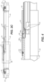
- the plug then extends distally as a cylindrical outer shell 22 slidingly disposed over, and surrounding, a cylindrical inner shell 24 .
- the outer shell is in an unlocked position, as shown in FIGS. 1-2B .
- the inner shell 24 and slidable outer shell 22 each extend to a distal end 26 , 28 , respectively, which are coplanar when the outer shell is fully retracted in the most proximal position, as shown in FIG. 1 .
- the mounting portion further includes an upper rim 33 .
- the second connector housing i.e., receptacle 14
- the second connector housing is in most respects a mirror image of the plug 12 . It includes a backshell body 40 having an open proximal end 42 and a locking collar 44 , where cables/wire conductors are inserted and secured.
- An integral outer shell 46 extends from the backshell body 40 , has a diameter equivalent to the diameter of the inner shell 24 of the plug 12 , and a distal end 48 that abuts the distal end 28 of the inner shell 24 of the plug portion 12 when the pair (plug and receptacle) are mated.
- the receptacle mounting portion includes complementary edges 53 having dimensions substantially identical to those of the plug mounting portion upper edges 33 .
- the outer shell 46 of receptacle 14 has a distal edge 62 that abuts the distal end 38 of the mounting portion 30 of plug 12 (see FIG. 2B ).
- Modular insulators 70 are disposed on the mounting portions 30 , 50 of the plug and receptacle 12 , 14 , respectively. They are separated along the length of the mounting portion in each of the plug and receptacle by keyway spacers 64 , 66 , slidingly inserted into the keyways 32 , 34 , and 52 , 54 .
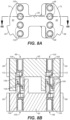
- the modular insulators include generally symmetrical first and second dielectric blocks 72 , 74 each having a mating face 76 , 78 , configured for aligning and indexing with a corresponding and matched modular insulator in an inverted orientation, as seen in FIGS. 2A-3 and FIGS. 8A-8B .
- Each dielectric block also includes a back face 80 , 82 , into which crimped conductors are inserted (see exp. FIGS. 7B and 8B ). Further, each dielectric block includes a curved outer sidewall surface 84 , 86 which closely conforms to the shape of the interior walls 36 , 56 of the module mounting portions 30 and 50 of the plug and receptacle, respectively. First and second tabs or keying features 88 , 90 , are integral with the outer sidewall surfaces.
- the dielectric blocks 72 , 74 are joined by a bridge 92 or cross bar sized to define a space within the enclosed connector for upper and lower wire passageways 94 , 96 .
- the keying features 88 , 90 are aligned with the open keyway slots 32 , 34 , and 52 , 54 at the ends 38 , 48 , of the plug 12 and receptacle 14 , respectively, and are translated longitudinally by sliding them proximally. As noted above, spacing between the insulator modules is maintained by keyway spacers 64 , 66 .
- each dielectric block Longitudinally disposed through each dielectric block are vertically stacked through bores 98 , 100 , which extend from the back faces 80 , 82 , to the mating faces 76 , 78 .
- the throughbores are configured to accommodate a crimp contact 102 having an integral cylindrical conductor crimp portion 104 and an elongate spring contact element 106 cantilevered forwardly from the crimp portion.
- the dimensions of the crimp portion may be tailored to the necessary strip length of the wires to be inserted.
- the spring contact element includes a medial ridge 108 which is driven down by the interaction of a cam portion 110 with a shelf 112 in the throughbore 98 , 100 and then snaps back and up to engage the shelf when fully inserted, in the manner of a cantilever snap fit.
- each insulator module installed in the connectors is a function of the number of conductors to be managed. As seen in the embodiment above, each insulator module includes eight throughbores, and thus may terminate eight different conductors. While this number may be varied according to need, it will be appreciated that if it is desired to provide more than eight conductors be terminated and connected, more than one insulator module may be placed in the plug, with a complementary mating insulator module in the receptacle.
- the most distal insulator modules in the plug mates with the most proximal module in the receptacle, and visa versa.
- Medial modules mate with medial modules, and so forth. Accordingly, the direction of termination points for terminated conductors in the plug will progress inversely to the expansion in the receptacle: one will progress in the proximal direction and the other will progress in the distal direction.
- any new or additional conductors must be terminated in a different insulator module for each of the plug and receptacle.
- Addressing the need to expand to a next insulator module thus entails merely mounting an additional module in each of the plug and receptacle and matching the plug contact with the correspondingly new receptacle contact. In other words, the "expansion" progress in a purely longitudinal direction. Thus, there is no need to expand the outer diameter of the electrical connector housing to accommodate further cables or conductors terminated in the matable elements.
- FIGS. 2A-4 it is seen in FIG. 2A that the receptacle 14 is rotated about its axis 180 degrees and positioned for radial mating with plug 12 .
- FIG. 2B shows that the distal end 48 of the mounting portion 50 of the receptacle is approximated to the distal ends of the outer shell 22 and inner shell 24 of the plug, and the distal end 38 of the plug is approximated to the distal end 62 of the outer shell of the receptacle, while the upper edge 33 of the mounting portion 30 of the plug is approximated to the upper edge 53 of the mounting portion 50 of the receptacle.
- the insulator modules are initially offset or staggered in relation to one another when the radial mating is accomplished, and then after radial mating, the plug and receptacle and translated longitudinally toward one another to effect insertion of the cantilevered beam (i.e., male element) 58 into socket 60 (see FIGS. 2A-2B ), and to bring the mating faces 76/78 into engagement sufficiently to drive the spring contact elements 106 in the aligned throughbores 98/100 into contact (see esp. FIG. 8B ).
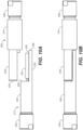
- Front and rear ramps 58a/58b on the male element 58 facilitate deflection to enable its insertion into socket 60 , as well as removal from molded hole 116 (see FIG. 4 ).
- the mated pair of plug and receptacle are then locked together by sliding outer shell 22 longitudinally toward the receptacle.
- the outer shell slides over the mated mounting portions and locks over a spring latch 120 , which engages a recess 122 in outer shell 22 .
- This is the locked configuration for an embodiment of the electrical connector.
- the plug 202 includes a longitudinally oriented PCB 204 having array of vertically disposed spring pin contacts 206 , which are radially mated with a complementary array of plated holes 208 in a PCB 210 in the receptacle 212 .
- the plug 202 includes an outer shell 214 slidingly disposed over an inner shell 216 , the later extending distally into a truncated cylindrical (arcuate) mounting portion 218 having a distal end 220 and an upper edge 222 .
- the PCB is mounted on a shelf so as to provide a clearance 224 underneath (above, when inverted).
- Backshell 226 and backshell opening 228 are structurally and functionally comparable to those earlier described.
- an integral arcuate shelf 219 extends from the distal end 217 of the inner shell 216 to provide a support for a complementary element, lip 239 , on the receptacle mounting portion, described below.
- the receptacle 212 also includes a backshell 230 and backshell opening 232 , as well as an outer shell 234 which extends to a distal end 235 and then further distally to a truncated cylindrical (arcuate) mounting portion 236 , which has a distal end 238 extending further to a lower lip 239 , as well as an upper edge 240 .
- the degrees of arc described by the receptacle mounting portion complements the degrees of arc described by the plug mounting portion such that together they describe a full 360 degrees of arc.
- the receptacle PCB 210 is configured with lateral tabs 242 which insert into slots 244 in the plug mounting portion inner wall 246 .
- the PCB is mounted on a mounting block 250 which secures and stabilizes the PCB and separates the PCB from the mounting portion inner wall 252 so as to provide clearance 254 for the spring contacts 206 to insert.
- the spring contact PCB 204 includes an inner (or lower) board portion 204a and an outer (or upper) board portion 204b .
- the inner board portion includes an array of plated through-holes 207 for terminating wire/cable conductors, each through-hole one mapped and connected to a corresponding spring contact 206 on the outer board portion 204b a circuit trace (not shown).
- the spring contacts 206 are each soldered in plated through-holes on the outer board 204b .
- the formed spring contacts 206 themselves comprise opposing bowed resilient conductive metal springs formed from wire which together form an upright selectively insertable/removable compressible spring contact.
- the spring contacts each removably mate to the inside walls of corresponding plated through-holes 208a in the receptacle PCB 210 .
- the deflected spring contact applies a normal force to the mating plated through-hole to maximize the electrical contact force while minimizing insertion and removal force.
- the receptacle PCB 210 also includes an outer board 210a and an inner board 210b, each including plated through-holes, 208a , 208b , each inner board through-hole 208b mapped to and electrically connected to a plated through-hole 208a in the outer board 210a through a circuit trace.
- the spring contacts and through-holes are arranged in rows of two contacts and any of a number of columns, the latter oriented generally longitudinally.
- mating the plug and receptacle involves rotating these structures so that the printed circuit boards 204 , 210 are facing one another and the spring contacts 206 of the plug circuit board 204 are aligned for insertion into the plated through-holes 208 of the receptacle printed circuit board 210 . Accordingly, the selective mating is exclusively radial, and no longitudinal translation is involved after radial mating. Indeed, such movement is contraindicated, which is why structure is provided to entirely prevent it.
- the sliding outer shell 214 is translated down the plug barrel over the receptacle mounting portion 236 until a detent 258 engages a locking spring 260 . This prevents radial separation of the plug and receptacle and provides enhanced environmental protection for the electronics.
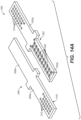
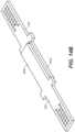
- FIGS. 14A-14B An alternative PCB pairing 300 is shown in FIGS. 14A-14B , where there is shown an interposer board 302 for a plug member and having an array of uncompressed spring contacts 304 configured for pairing with a PCB 306 in a receptacle and having an array of plated conductive (preferably gold plated) pads 308 (not shown) disposed on the underside 310 of the PCB, and well known in the art.
- the interposer board includes an inboard/proximal portion 302a and an outboard/distal portion 302b .
- the conductive pads 308 on the PCB are mapped to and electrically connected by circuit traces to plated through-holes 312 used for terminating conductors, and the spring contacts 304 are electrically connected to plated through-holes 314 .
- the pitch, working range, and spring constant are tailored to ensure that the deflected contacts apply a normal force to the mating plated pads, and the contact force equals the mating force.
- the receptacle PCB also includes an inboard/proximal portion 306a and an outboard/distal portion 306b .
- spring contacts, pads, and through-holes are all arranged in rows and columns, the latter running generally longitudinally.
- an initial terminating plan may not call for terminating a number of cables or conductors that would make use of all of the conductor terminating points 207/208b, and 312/314 on the inner portions of the PCBs.
- "expansion” entails connecting additional conductors down the column, either in the distal or proximal direction, in the discretion of the user. In either case, no expansion of the outer diameter of the connector housings is required. Indeed, if necessary, within the dimensional constraints of the connector housings, the PCBs can be replaced with boards having more longitudinally oriented termination and contact points.
- the electrical connector of the present invention is configured to accommodate increasingly large numbers of conductors without having to expand the circumference or outer diameter of the terminal portions of either the plug or receptacle.
- longitudinally disposed insulator modules are added to provide an increasing number of connectable contacts.
- Each module accommodates eight (8) more wires, without any increase in the diameter of the connector.
- Including more conductors (in number or size or both) in the embodiments shown in FIGS. 9-14B simply involves terminating wires in the properly identified corresponding plated holes in the respective plug and receptacle PCBs.
- the connector housings need not be cylindrical in shape (circular in cross section).
- the invention naturally encompasses alternative geometries without any impact on function, such geometries most notably including elongate cuboid (square or rectangular in cross section).
- the insulator modules would be modified correspondingly, with keying features fitted to keyways disposed in the sidewalls of the cuboid plug and receptacle mounting portion structures.
- the electrical connector of the present invention will be seen to include a plug member including a housing having an elongate tubular housing portion and a partially open mounting portion integrally extending from the tubular portion and configured for mating with a complementary receptacle, and a longitudinally oriented array of male electrical elements; a receptacle including a housing having an elongate tubular housing portion and a partially open mounting portion integrally extending from the tubular portion and configured for mating with the plug, wherein when the plug and the receptacle are mated, the partially open portions combine to form a tubular enclosure axially continuous with the tubular housing portions, and longitudinally oriented array of female electrical elements; and a locking structure to lock the plug and the receptacle into a mated configuration.
Landscapes
- Engineering & Computer Science (AREA)
- Aviation & Aerospace Engineering (AREA)
- Details Of Connecting Devices For Male And Female Coupling (AREA)
- Coupling Device And Connection With Printed Circuit (AREA)
Claims (8)
- Connecteur électrique extensible longitudinalement (10), comprenant :une fiche (12) incluant une extrémité proximale de fiche (20) présentant une ouverture à travers laquelle introduire des conducteurs, une coque interne de fiche (24) s'étendant de manière distale à partir de ladite extrémité proximale de fiche (20) et présentant une extrémité distale de coque interne de fiche (28), une partie de montage de fiche tubulaire partielle allongée (30) s'étendant de manière distale à partir de ladite extrémité distale de coque interne de fiche (28), ladite partie de montage de fiche (30) présentant une paroi interne de partie de montage de fiche avec des bords supérieurs (33) et une extrémité distale de partie de montage de fiche (38) ;un logement (14) configuré de manière complémentaire à ladite fiche (12) et incluant une extrémité proximale de logement (42) présentant une ouverture à travers laquelle introduire des conducteurs, une coque externe de logement (46) s'étendant de manière distale à partir de ladite extrémité proximale de logement (42) et présentant une extrémité distale de coque externe de logement (62), une partie de montage de logement tubulaire partielle allongée (50) s'étendant de manière distale à partir de ladite extrémité distale de coque externe de logement (62), ladite partie de montage de logement (50) présentant une paroi interne de partie de montage de logement (56) avec des bords complémentaires (53) et une extrémité distale de partie de montage de logement (48), ladite partie de montage de logement (50) étant configurée de telle sorte que lorsque lesdits bords supérieurs (33) de ladite partie de montage de fiche (30) sont alignés et rapprochés desdits bords complémentaires (53) de ladite partie de montage de logement (50) de manière à apparier ledit logement (14) avec ladite fiche (12), ladite partie de montage de fiche (30) et ladite partie de montage de logement (50) forment une enceinte tubulaire et lesdits bords supérieurs (33) de ladite partie de montage de fiche (30) sont rapprochés desdits bords complémentaires (53) de ladite partie de montage de logement (50) ;un réseau de contacts de fiche orientés longitudinalement disposé dans ladite partie de montage de fiche (30) et présentant une pluralité de points de terminaison pour terminer les conducteurs et une pluralité de contacts (106) pour un contact électrique pouvant être apparié avec un réseau complémentaire dans ledit logement (50) ;un réseau de contacts de logement orientés longitudinalement disposé dans ladite partie de montage de logement (50) complémentaire dudit réseau de contacts de fiche et présentant une pluralité de contacts (106) configurés pour s'apparier électriquement avec ladite pluralité de contacts (106) dans ledit réseau de contacts de fiche ; etun élément de verrouillage pour verrouiller ladite fiche (12) et ledit logement (14) dans une configuration appariée pour empêcher une séparation radiale de ladite fiche (12) et dudit logement (14), dans lequel lorsque ladite fiche (12) et ledit logement (14) sont dans la configuration appariée, ladite extrémité distale de coque interne de fiche (28) se rapproche de l'extrémité distale de partie de montage de logement (48), et ladite extrémité distale de coque externe de logement (62) se rapproche de l'extrémité distale de partie de montage de fiche (38) ;caractérisé en ce que chacun dudit réseau de contacts de fiche et dudit réseau de contacts de logement inclut une pluralité d'isolateurs modulaires espacés longitudinalement (70), lesdits isolateurs modulaires incluant une face d'appariement (76, 78), une face arrière (80, 82) et une pluralité d'alésages traversants orientés longitudinalement (98, 100), chacun desdits alésages traversants étant configuré pour recevoir des contacts électriques et pour terminer des conducteurs électriques, dans lequel l'isolateur modulaire le plus distal (70) dans ladite fiche (12) s'apparie avec l'isolateur modulaire le plus proximal (70) dans ledit logement (14) par translation longitudinale de ladite prise (12) par rapport audit logement (14).
- Connecteur électrique selon la revendication 1, incluant en outre une coque arrière (16, 40) sur chacun de ladite fiche (12) et dudit logement (14), dans lequel la coque arrière (16) sur la fiche (12) est soit disposée sur ladite coque interne de fiche (24), soit solidaire de celle-ci et dans lequel la coque arrière (40) sur le logement est soit disposée sur ladite coque externe de logement (46), soit solidaire de celle-ci.
- Connecteur électrique selon la revendication 1, dans lequel ledit élément de verrouillage est une coque externe disposée de manière coulissante sur ladite coque interne (24) de ladite fiche (12) lorsqu'elle est dans une configuration déverrouillée.
- Connecteur électrique selon la revendication 1, dans lequel l'appariement de ladite fiche (12) et dudit logement (14) est réalisé par l'intermédiaire d'une combinaison de translation radiale et de translation longitudinale.
- Connecteur électrique selon la revendication 1, dans lequel ladite coque interne de fiche (24) inclut une prise et ladite extrémité distale (48) de ladite partie de montage de logement inclut un élément encliquetable (58) pour une insertion à verrouillage libérable dans ladite prise (60).
- Connecteur électrique selon la revendication 1, dans lequel chacune de ladite partie de montage de fiche (30) et de ladite partie de montage de logement (50) inclut des rainures de clavette (32, 34, 52, 54) sur des parois intérieures et lesdits isolateurs modulaires (70) incluent des éléments de surface qui s'insèrent de manière coulissante dans lesdites rainures de clavette.
- Connecteur électrique selon la revendication 1, dans lequel la fiche (12) comprend un boîtier de fiche et le logement (14) comprend un boîtier de logement et dans lequel le boîtier de fiche et le boîtier de logement sont circulaires en coupe transversale.
- Connecteur électrique selon la revendication 1, dans lequel la fiche (12) comprend un boîtier de fiche et le logement comprend un boîtier de logement et dans lequel le boîtier de fiche et le boîtier de logement ne sont pas circulaires en coupe transversale.
Applications Claiming Priority (2)
| Application Number | Priority Date | Filing Date | Title |
|---|---|---|---|
| US15/950,117 US10283896B1 (en) | 2018-04-10 | 2018-04-10 | Longitudinally expandable electrical connector |
| PCT/US2019/026670 WO2019199892A1 (fr) | 2018-04-10 | 2019-04-09 | Connecteur électrique extensible longitudinalement |
Publications (3)
| Publication Number | Publication Date |
|---|---|
| EP3776749A1 EP3776749A1 (fr) | 2021-02-17 |
| EP3776749A4 EP3776749A4 (fr) | 2021-05-05 |
| EP3776749B1 true EP3776749B1 (fr) | 2023-12-13 |
Family
ID=66333670
Family Applications (1)
| Application Number | Title | Priority Date | Filing Date |
|---|---|---|---|
| EP19786223.8A Active EP3776749B1 (fr) | 2018-04-10 | 2019-04-09 | Connecteur électrique extensible longitudinalement |
Country Status (4)
| Country | Link |
|---|---|
| US (1) | US10283896B1 (fr) |
| EP (1) | EP3776749B1 (fr) |
| CN (1) | CN112470346B (fr) |
| WO (1) | WO2019199892A1 (fr) |
Families Citing this family (4)
| Publication number | Priority date | Publication date | Assignee | Title |
|---|---|---|---|---|
| DE102018214228A1 (de) * | 2018-08-23 | 2020-02-27 | Brose Fahrzeugteile Gmbh & Co. Kommanditgesellschaft, Bamberg | Elektronik eines Elektromotors eines Kraftfahrzeugs |
| JP6706302B2 (ja) * | 2018-10-01 | 2020-06-03 | 日本航空電子工業株式会社 | コネクタ組立体及びコネクタ |
| US11171438B2 (en) * | 2020-04-09 | 2021-11-09 | Energy Services LLC | Unitized cable plug array for mobile power generation equipment |
| TWM625608U (zh) * | 2021-12-09 | 2022-04-11 | 連展科技股份有限公司 | 車用連接器 |
Family Cites Families (15)
| Publication number | Priority date | Publication date | Assignee | Title |
|---|---|---|---|---|
| US526078A (en) * | 1894-09-18 | Electrical connector | ||
| US3065446A (en) * | 1958-09-29 | 1962-11-20 | Cannon Electric Co | Electrical connector for strip cable |
| US4045107A (en) * | 1975-08-22 | 1977-08-30 | Walker-Hall-Sears, Inc. | Multi-contact connectors with identical contacts |
| US4166663A (en) * | 1976-11-11 | 1979-09-04 | Western Geophysical Co. Of America | Multi-contact connectors with individual resilient contact inserts |
| US4230389A (en) * | 1978-12-28 | 1980-10-28 | Amerace Corporation | Flexible electrical connector assembly |
| US4500980A (en) * | 1981-08-24 | 1985-02-19 | Whitehall Corporation | Seismic streamer connector assembly |
| US6305962B1 (en) * | 1999-02-16 | 2001-10-23 | Nimbus, Incorporated | Inline cable connector |
| US6283768B1 (en) * | 1999-05-13 | 2001-09-04 | Ideal Industries, Inc. | RJ-45 style modular connector |
| US6568966B1 (en) * | 2001-11-08 | 2003-05-27 | Hon Hai Precision Ind. Co., Ltd. | Stacked modular jack assembly having improved magnetic module |
| JP4852026B2 (ja) * | 2007-04-26 | 2012-01-11 | 京セラエルコ株式会社 | コネクタ及びコネクタの製造方法 |
| US7871296B2 (en) * | 2008-12-05 | 2011-01-18 | Tyco Electronics Corporation | High-speed backplane electrical connector system |
| EP2715882B1 (fr) * | 2011-05-26 | 2017-09-06 | GN Audio A/S | Dispositif de connexion électrique hermaphrodite à éléments de contact additionnels |
| CN203312524U (zh) * | 2013-06-26 | 2013-11-27 | 无锡市市北高级中学 | 柱式插座 |
| JP6126749B2 (ja) * | 2013-08-02 | 2017-05-10 | モレックス エルエルシー | 電力コネクタ |
| US9437961B1 (en) * | 2015-10-02 | 2016-09-06 | Westinghouse Air Brake Technologies Corporation | Two mating electrical power connector assemblies having identical configurations |
-
2018
- 2018-04-10 US US15/950,117 patent/US10283896B1/en active Active
-
2019
- 2019-04-09 WO PCT/US2019/026670 patent/WO2019199892A1/fr not_active Ceased
- 2019-04-09 CN CN201980031718.8A patent/CN112470346B/zh active Active
- 2019-04-09 EP EP19786223.8A patent/EP3776749B1/fr active Active
Also Published As
| Publication number | Publication date |
|---|---|
| CN112470346B (zh) | 2023-01-10 |
| WO2019199892A1 (fr) | 2019-10-17 |
| US10283896B1 (en) | 2019-05-07 |
| CN112470346A (zh) | 2021-03-09 |
| EP3776749A1 (fr) | 2021-02-17 |
| EP3776749A4 (fr) | 2021-05-05 |
Similar Documents
| Publication | Publication Date | Title |
|---|---|---|
| EP3776749B1 (fr) | Connecteur électrique extensible longitudinalement | |
| US4749357A (en) | Circuit board connector, bus and system | |
| US10535956B2 (en) | Electrical device having an impedance control body | |
| US6042394A (en) | Right-angle connector | |
| EP0993994B1 (fr) | Faisceau pour un réseau de bord d'une automobile présentant une structure en sandwich | |
| US9385466B2 (en) | Retention features for cable assembly of a pluggable connector | |
| EP2345112B1 (fr) | Connecteurs circulaires avec agencement de brochage de contact de signal et de puissance | |
| US5114364A (en) | Shielded connector | |
| US5709557A (en) | Electrical connector for dual printed circuit boards | |
| EP0357375A2 (fr) | Connecteur modulaire à tiroir | |
| EP1009070B1 (fr) | Connecteur électrique filtré avec multiples éléments de ferrite | |
| JPH07201400A (ja) | シールドケーブル用のコネクタ | |
| EP1894277A1 (fr) | Systeme d'interconnexion electrique | |
| EP2345111A1 (fr) | Connecteurs avec structures de contact de signal et de puissance | |
| EP0582264B1 (fr) | Connecteur électrique pour des plaquettes de circuits imprimés | |
| US5030121A (en) | Electrical connector with contact wiping action | |
| EP0074205B1 (fr) | Connecteur pour un câble coaxial blindé | |
| EP0393879B1 (fr) | Système de connecteur électrique et terminaux pénétrants l'isolation pour un tel système | |
| US5997348A (en) | Electrical assembly with grounding strip connecting cable screens | |
| US11909147B2 (en) | Cable connector assembly | |
| DE10338279B4 (de) | Steckverbindervorrichtung | |
| CN100578867C (zh) | 电连接器组件 | |
| GB2287140A (en) | Connector for a multipolar flat strip cable | |
| EP0739061A1 (fr) | Connecteur à angle droit avec embout séparé | |
| GB2207011A (en) | Earth connector |
Legal Events
| Date | Code | Title | Description |
|---|---|---|---|
| STAA | Information on the status of an ep patent application or granted ep patent |
Free format text: STATUS: THE INTERNATIONAL PUBLICATION HAS BEEN MADE |
|
| PUAI | Public reference made under article 153(3) epc to a published international application that has entered the european phase |
Free format text: ORIGINAL CODE: 0009012 |
|
| STAA | Information on the status of an ep patent application or granted ep patent |
Free format text: STATUS: REQUEST FOR EXAMINATION WAS MADE |
|
| 17P | Request for examination filed |
Effective date: 20201105 |
|
| AK | Designated contracting states |
Kind code of ref document: A1 Designated state(s): AL AT BE BG CH CY CZ DE DK EE ES FI FR GB GR HR HU IE IS IT LI LT LU LV MC MK MT NL NO PL PT RO RS SE SI SK SM TR |
|
| AX | Request for extension of the european patent |
Extension state: BA ME |
|
| STAA | Information on the status of an ep patent application or granted ep patent |
Free format text: STATUS: EXAMINATION IS IN PROGRESS |
|
| A4 | Supplementary search report drawn up and despatched |
Effective date: 20210406 |
|
| RIC1 | Information provided on ipc code assigned before grant |
Ipc: H01R 13/639 20060101AFI20210329BHEP Ipc: H01R 12/58 20110101ALN20210329BHEP Ipc: H01R 13/28 20060101ALN20210329BHEP Ipc: H01R 13/627 20060101ALN20210329BHEP Ipc: H01R 24/84 20110101ALN20210329BHEP |
|
| 17Q | First examination report despatched |
Effective date: 20210503 |
|
| DAV | Request for validation of the european patent (deleted) | ||
| DAX | Request for extension of the european patent (deleted) | ||
| RAP3 | Party data changed (applicant data changed or rights of an application transferred) |
Owner name: SAFRAN ELECTRICAL COMPONENTS USA, INC. |
|
| REG | Reference to a national code |
Ref country code: DE Ref legal event code: R079 Free format text: PREVIOUS MAIN CLASS: H01R0013500000 Ipc: H01R0013639000 Ref document number: 602019043293 Country of ref document: DE |
|
| GRAP | Despatch of communication of intention to grant a patent |
Free format text: ORIGINAL CODE: EPIDOSNIGR1 |
|
| STAA | Information on the status of an ep patent application or granted ep patent |
Free format text: STATUS: GRANT OF PATENT IS INTENDED |
|
| RIC1 | Information provided on ipc code assigned before grant |
Ipc: H01R 24/84 20110101ALN20230706BHEP Ipc: H01R 13/627 20060101ALN20230706BHEP Ipc: H01R 13/28 20060101ALN20230706BHEP Ipc: H01R 12/58 20110101ALN20230706BHEP Ipc: H01R 13/639 20060101AFI20230706BHEP |
|
| INTG | Intention to grant announced |
Effective date: 20230719 |
|
| GRAS | Grant fee paid |
Free format text: ORIGINAL CODE: EPIDOSNIGR3 |
|
| GRAA | (expected) grant |
Free format text: ORIGINAL CODE: 0009210 |
|
| STAA | Information on the status of an ep patent application or granted ep patent |
Free format text: STATUS: THE PATENT HAS BEEN GRANTED |
|
| AK | Designated contracting states |
Kind code of ref document: B1 Designated state(s): AL AT BE BG CH CY CZ DE DK EE ES FI FR GB GR HR HU IE IS IT LI LT LU LV MC MK MT NL NO PL PT RO RS SE SI SK SM TR |
|
| REG | Reference to a national code |
Ref country code: GB Ref legal event code: FG4D |
|
| REG | Reference to a national code |
Ref country code: CH Ref legal event code: EP |
|
| REG | Reference to a national code |
Ref country code: DE Ref legal event code: R096 Ref document number: 602019043293 Country of ref document: DE |
|
| REG | Reference to a national code |
Ref country code: IE Ref legal event code: FG4D |
|
| PG25 | Lapsed in a contracting state [announced via postgrant information from national office to epo] |
Ref country code: GR Free format text: LAPSE BECAUSE OF FAILURE TO SUBMIT A TRANSLATION OF THE DESCRIPTION OR TO PAY THE FEE WITHIN THE PRESCRIBED TIME-LIMIT Effective date: 20240314 |
|
| REG | Reference to a national code |
Ref country code: LT Ref legal event code: MG9D |
|
| PG25 | Lapsed in a contracting state [announced via postgrant information from national office to epo] |
Ref country code: LT Free format text: LAPSE BECAUSE OF FAILURE TO SUBMIT A TRANSLATION OF THE DESCRIPTION OR TO PAY THE FEE WITHIN THE PRESCRIBED TIME-LIMIT Effective date: 20231213 |
|
| REG | Reference to a national code |
Ref country code: NL Ref legal event code: MP Effective date: 20231213 |
|
| PG25 | Lapsed in a contracting state [announced via postgrant information from national office to epo] |
Ref country code: ES Free format text: LAPSE BECAUSE OF FAILURE TO SUBMIT A TRANSLATION OF THE DESCRIPTION OR TO PAY THE FEE WITHIN THE PRESCRIBED TIME-LIMIT Effective date: 20231213 |
|
| PG25 | Lapsed in a contracting state [announced via postgrant information from national office to epo] |
Ref country code: LT Free format text: LAPSE BECAUSE OF FAILURE TO SUBMIT A TRANSLATION OF THE DESCRIPTION OR TO PAY THE FEE WITHIN THE PRESCRIBED TIME-LIMIT Effective date: 20231213 Ref country code: GR Free format text: LAPSE BECAUSE OF FAILURE TO SUBMIT A TRANSLATION OF THE DESCRIPTION OR TO PAY THE FEE WITHIN THE PRESCRIBED TIME-LIMIT Effective date: 20240314 Ref country code: ES Free format text: LAPSE BECAUSE OF FAILURE TO SUBMIT A TRANSLATION OF THE DESCRIPTION OR TO PAY THE FEE WITHIN THE PRESCRIBED TIME-LIMIT Effective date: 20231213 Ref country code: BG Free format text: LAPSE BECAUSE OF FAILURE TO SUBMIT A TRANSLATION OF THE DESCRIPTION OR TO PAY THE FEE WITHIN THE PRESCRIBED TIME-LIMIT Effective date: 20240313 |
|
| REG | Reference to a national code |
Ref country code: AT Ref legal event code: MK05 Ref document number: 1641282 Country of ref document: AT Kind code of ref document: T Effective date: 20231213 |
|
| PG25 | Lapsed in a contracting state [announced via postgrant information from national office to epo] |
Ref country code: NL Free format text: LAPSE BECAUSE OF FAILURE TO SUBMIT A TRANSLATION OF THE DESCRIPTION OR TO PAY THE FEE WITHIN THE PRESCRIBED TIME-LIMIT Effective date: 20231213 |
|
| PG25 | Lapsed in a contracting state [announced via postgrant information from national office to epo] |
Ref country code: SE Free format text: LAPSE BECAUSE OF FAILURE TO SUBMIT A TRANSLATION OF THE DESCRIPTION OR TO PAY THE FEE WITHIN THE PRESCRIBED TIME-LIMIT Effective date: 20231213 Ref country code: RS Free format text: LAPSE BECAUSE OF FAILURE TO SUBMIT A TRANSLATION OF THE DESCRIPTION OR TO PAY THE FEE WITHIN THE PRESCRIBED TIME-LIMIT Effective date: 20231213 Ref country code: NO Free format text: LAPSE BECAUSE OF FAILURE TO SUBMIT A TRANSLATION OF THE DESCRIPTION OR TO PAY THE FEE WITHIN THE PRESCRIBED TIME-LIMIT Effective date: 20240313 Ref country code: NL Free format text: LAPSE BECAUSE OF FAILURE TO SUBMIT A TRANSLATION OF THE DESCRIPTION OR TO PAY THE FEE WITHIN THE PRESCRIBED TIME-LIMIT Effective date: 20231213 Ref country code: LV Free format text: LAPSE BECAUSE OF FAILURE TO SUBMIT A TRANSLATION OF THE DESCRIPTION OR TO PAY THE FEE WITHIN THE PRESCRIBED TIME-LIMIT Effective date: 20231213 Ref country code: HR Free format text: LAPSE BECAUSE OF FAILURE TO SUBMIT A TRANSLATION OF THE DESCRIPTION OR TO PAY THE FEE WITHIN THE PRESCRIBED TIME-LIMIT Effective date: 20231213 |
|
| PG25 | Lapsed in a contracting state [announced via postgrant information from national office to epo] |
Ref country code: IS Free format text: LAPSE BECAUSE OF FAILURE TO SUBMIT A TRANSLATION OF THE DESCRIPTION OR TO PAY THE FEE WITHIN THE PRESCRIBED TIME-LIMIT Effective date: 20240413 |
|
| PG25 | Lapsed in a contracting state [announced via postgrant information from national office to epo] |
Ref country code: AT Free format text: LAPSE BECAUSE OF FAILURE TO SUBMIT A TRANSLATION OF THE DESCRIPTION OR TO PAY THE FEE WITHIN THE PRESCRIBED TIME-LIMIT Effective date: 20231213 Ref country code: CZ Free format text: LAPSE BECAUSE OF FAILURE TO SUBMIT A TRANSLATION OF THE DESCRIPTION OR TO PAY THE FEE WITHIN THE PRESCRIBED TIME-LIMIT Effective date: 20231213 |
|
| PG25 | Lapsed in a contracting state [announced via postgrant information from national office to epo] |
Ref country code: SK Free format text: LAPSE BECAUSE OF FAILURE TO SUBMIT A TRANSLATION OF THE DESCRIPTION OR TO PAY THE FEE WITHIN THE PRESCRIBED TIME-LIMIT Effective date: 20231213 |
|
| PG25 | Lapsed in a contracting state [announced via postgrant information from national office to epo] |
Ref country code: SM Free format text: LAPSE BECAUSE OF FAILURE TO SUBMIT A TRANSLATION OF THE DESCRIPTION OR TO PAY THE FEE WITHIN THE PRESCRIBED TIME-LIMIT Effective date: 20231213 Ref country code: SK Free format text: LAPSE BECAUSE OF FAILURE TO SUBMIT A TRANSLATION OF THE DESCRIPTION OR TO PAY THE FEE WITHIN THE PRESCRIBED TIME-LIMIT Effective date: 20231213 Ref country code: RO Free format text: LAPSE BECAUSE OF FAILURE TO SUBMIT A TRANSLATION OF THE DESCRIPTION OR TO PAY THE FEE WITHIN THE PRESCRIBED TIME-LIMIT Effective date: 20231213 Ref country code: IT Free format text: LAPSE BECAUSE OF FAILURE TO SUBMIT A TRANSLATION OF THE DESCRIPTION OR TO PAY THE FEE WITHIN THE PRESCRIBED TIME-LIMIT Effective date: 20231213 Ref country code: IS Free format text: LAPSE BECAUSE OF FAILURE TO SUBMIT A TRANSLATION OF THE DESCRIPTION OR TO PAY THE FEE WITHIN THE PRESCRIBED TIME-LIMIT Effective date: 20240413 Ref country code: EE Free format text: LAPSE BECAUSE OF FAILURE TO SUBMIT A TRANSLATION OF THE DESCRIPTION OR TO PAY THE FEE WITHIN THE PRESCRIBED TIME-LIMIT Effective date: 20231213 Ref country code: CZ Free format text: LAPSE BECAUSE OF FAILURE TO SUBMIT A TRANSLATION OF THE DESCRIPTION OR TO PAY THE FEE WITHIN THE PRESCRIBED TIME-LIMIT Effective date: 20231213 Ref country code: AT Free format text: LAPSE BECAUSE OF FAILURE TO SUBMIT A TRANSLATION OF THE DESCRIPTION OR TO PAY THE FEE WITHIN THE PRESCRIBED TIME-LIMIT Effective date: 20231213 |
|
| PG25 | Lapsed in a contracting state [announced via postgrant information from national office to epo] |
Ref country code: PL Free format text: LAPSE BECAUSE OF FAILURE TO SUBMIT A TRANSLATION OF THE DESCRIPTION OR TO PAY THE FEE WITHIN THE PRESCRIBED TIME-LIMIT Effective date: 20231213 Ref country code: PT Free format text: LAPSE BECAUSE OF FAILURE TO SUBMIT A TRANSLATION OF THE DESCRIPTION OR TO PAY THE FEE WITHIN THE PRESCRIBED TIME-LIMIT Effective date: 20240415 |
|
| PG25 | Lapsed in a contracting state [announced via postgrant information from national office to epo] |
Ref country code: PT Free format text: LAPSE BECAUSE OF FAILURE TO SUBMIT A TRANSLATION OF THE DESCRIPTION OR TO PAY THE FEE WITHIN THE PRESCRIBED TIME-LIMIT Effective date: 20240415 Ref country code: PL Free format text: LAPSE BECAUSE OF FAILURE TO SUBMIT A TRANSLATION OF THE DESCRIPTION OR TO PAY THE FEE WITHIN THE PRESCRIBED TIME-LIMIT Effective date: 20231213 |
|
| REG | Reference to a national code |
Ref country code: DE Ref legal event code: R097 Ref document number: 602019043293 Country of ref document: DE |
|
| PG25 | Lapsed in a contracting state [announced via postgrant information from national office to epo] |
Ref country code: DK Free format text: LAPSE BECAUSE OF FAILURE TO SUBMIT A TRANSLATION OF THE DESCRIPTION OR TO PAY THE FEE WITHIN THE PRESCRIBED TIME-LIMIT Effective date: 20231213 |
|
| PLBE | No opposition filed within time limit |
Free format text: ORIGINAL CODE: 0009261 |
|
| STAA | Information on the status of an ep patent application or granted ep patent |
Free format text: STATUS: NO OPPOSITION FILED WITHIN TIME LIMIT |
|
| PG25 | Lapsed in a contracting state [announced via postgrant information from national office to epo] |
Ref country code: SI Free format text: LAPSE BECAUSE OF FAILURE TO SUBMIT A TRANSLATION OF THE DESCRIPTION OR TO PAY THE FEE WITHIN THE PRESCRIBED TIME-LIMIT Effective date: 20231213 |
|
| PG25 | Lapsed in a contracting state [announced via postgrant information from national office to epo] |
Ref country code: SI Free format text: LAPSE BECAUSE OF FAILURE TO SUBMIT A TRANSLATION OF THE DESCRIPTION OR TO PAY THE FEE WITHIN THE PRESCRIBED TIME-LIMIT Effective date: 20231213 Ref country code: DK Free format text: LAPSE BECAUSE OF FAILURE TO SUBMIT A TRANSLATION OF THE DESCRIPTION OR TO PAY THE FEE WITHIN THE PRESCRIBED TIME-LIMIT Effective date: 20231213 |
|
| 26N | No opposition filed |
Effective date: 20240916 |
|
| PG25 | Lapsed in a contracting state [announced via postgrant information from national office to epo] |
Ref country code: MC Free format text: LAPSE BECAUSE OF FAILURE TO SUBMIT A TRANSLATION OF THE DESCRIPTION OR TO PAY THE FEE WITHIN THE PRESCRIBED TIME-LIMIT Effective date: 20231213 |
|
| PG25 | Lapsed in a contracting state [announced via postgrant information from national office to epo] |
Ref country code: MC Free format text: LAPSE BECAUSE OF FAILURE TO SUBMIT A TRANSLATION OF THE DESCRIPTION OR TO PAY THE FEE WITHIN THE PRESCRIBED TIME-LIMIT Effective date: 20231213 |
|
| REG | Reference to a national code |
Ref country code: CH Ref legal event code: PL |
|
| PG25 | Lapsed in a contracting state [announced via postgrant information from national office to epo] |
Ref country code: LU Free format text: LAPSE BECAUSE OF NON-PAYMENT OF DUE FEES Effective date: 20240409 |
|
| REG | Reference to a national code |
Ref country code: BE Ref legal event code: MM Effective date: 20240430 |
|
| PG25 | Lapsed in a contracting state [announced via postgrant information from national office to epo] |
Ref country code: LU Free format text: LAPSE BECAUSE OF NON-PAYMENT OF DUE FEES Effective date: 20240409 |
|
| PG25 | Lapsed in a contracting state [announced via postgrant information from national office to epo] |
Ref country code: BE Free format text: LAPSE BECAUSE OF NON-PAYMENT OF DUE FEES Effective date: 20240430 |
|
| PG25 | Lapsed in a contracting state [announced via postgrant information from national office to epo] |
Ref country code: BE Free format text: LAPSE BECAUSE OF NON-PAYMENT OF DUE FEES Effective date: 20240430 Ref country code: CH Free format text: LAPSE BECAUSE OF NON-PAYMENT OF DUE FEES Effective date: 20240430 |
|
| PG25 | Lapsed in a contracting state [announced via postgrant information from national office to epo] |
Ref country code: IE Free format text: LAPSE BECAUSE OF NON-PAYMENT OF DUE FEES Effective date: 20240409 |
|
| PGFP | Annual fee paid to national office [announced via postgrant information from national office to epo] |
Ref country code: DE Payment date: 20250417 Year of fee payment: 7 |
|
| PGFP | Annual fee paid to national office [announced via postgrant information from national office to epo] |
Ref country code: FR Payment date: 20250428 Year of fee payment: 7 |
|
| PG25 | Lapsed in a contracting state [announced via postgrant information from national office to epo] |
Ref country code: CY Free format text: LAPSE BECAUSE OF FAILURE TO SUBMIT A TRANSLATION OF THE DESCRIPTION OR TO PAY THE FEE WITHIN THE PRESCRIBED TIME-LIMIT; INVALID AB INITIO Effective date: 20190409 |
|
| PG25 | Lapsed in a contracting state [announced via postgrant information from national office to epo] |
Ref country code: HU Free format text: LAPSE BECAUSE OF FAILURE TO SUBMIT A TRANSLATION OF THE DESCRIPTION OR TO PAY THE FEE WITHIN THE PRESCRIBED TIME-LIMIT; INVALID AB INITIO Effective date: 20190409 |
|
| PG25 | Lapsed in a contracting state [announced via postgrant information from national office to epo] |
Ref country code: FI Free format text: LAPSE BECAUSE OF FAILURE TO SUBMIT A TRANSLATION OF THE DESCRIPTION OR TO PAY THE FEE WITHIN THE PRESCRIBED TIME-LIMIT Effective date: 20231213 |
|
| PGFP | Annual fee paid to national office [announced via postgrant information from national office to epo] |
Ref country code: GB Payment date: 20260327 Year of fee payment: 8 |