EP3776764B1 - Compartiment pour module d'insertion - Google Patents
Compartiment pour module d'insertion Download PDFInfo
- Publication number
- EP3776764B1 EP3776764B1 EP18716992.5A EP18716992A EP3776764B1 EP 3776764 B1 EP3776764 B1 EP 3776764B1 EP 18716992 A EP18716992 A EP 18716992A EP 3776764 B1 EP3776764 B1 EP 3776764B1
- Authority
- EP
- European Patent Office
- Prior art keywords
- compartment
- module
- guide
- wall
- strip
- Prior art date
- Legal status (The legal status is an assumption and is not a legal conclusion. Google has not performed a legal analysis and makes no representation as to the accuracy of the status listed.)
- Active
Links
Images



Classifications
-
- H—ELECTRICITY
- H02—GENERATION; CONVERSION OR DISTRIBUTION OF ELECTRIC POWER
- H02B—BOARDS, SUBSTATIONS OR SWITCHING ARRANGEMENTS FOR THE SUPPLY OR DISTRIBUTION OF ELECTRIC POWER
- H02B1/00—Frameworks, boards, panels, desks, casings; Details of substations or switching arrangements
- H02B1/26—Casings; Parts thereof or accessories therefor
- H02B1/30—Cabinet-type casings; Parts thereof or accessories therefor
- H02B1/32—Mounting of devices therein
- H02B1/34—Racks
-
- H—ELECTRICITY
- H02—GENERATION; CONVERSION OR DISTRIBUTION OF ELECTRIC POWER
- H02B—BOARDS, SUBSTATIONS OR SWITCHING ARRANGEMENTS FOR THE SUPPLY OR DISTRIBUTION OF ELECTRIC POWER
- H02B1/00—Frameworks, boards, panels, desks, casings; Details of substations or switching arrangements
- H02B1/26—Casings; Parts thereof or accessories therefor
- H02B1/30—Cabinet-type casings; Parts thereof or accessories therefor
- H02B1/32—Mounting of devices therein
- H02B1/34—Racks
- H02B1/36—Racks with withdrawable units
Definitions
- a module which is configured as a so-called skeleton module has no side walls, no roof and no base wall. Modules of this type in which the electrical components carried by the module are substantially freely accessible, must be pushed into a slide-in compartment of the type described here for operational use.
- the slide-in compartment brings about a secure guidance of the module, ensures a correct contacting of electrical connections, brings about a secure locking and ensures that the type of protection is achieved.
- an arrangement comprises a slide-in compartment of the type described here and a module for insertion into a housing or for removal from a housing, wherein the module comprises a base body having a front wall and a rear wall, wherein parallel elongate strip parts extend between the front wall and the rear wall, the longitudinal extension whereof spaces apart the front wall and the rear wall, and wherein at least one strip part has a guide leg for cooperation with a guide counter-element.
- the guide leg has at least one recess.
- a recess or a plurality of recesses can constitute a mechanical coding so that a module can only be brought to a specific location in a housing or switchgear cabinet.
- the removable and movable module is designed so that four strip parts running depthwise, namely in the insertion direction, take over the mechanical connection of a front and a rear wall and also the guidance of the module in two directions.
- a strip part is a carrying part and a guide part.
- a separately removable control unit is also located in the module.
- the operating and display panel 8 of the control unit is also located in the front wall 2 and therefore is easily accessible.
- the rear wall 3 is provided for fastening primary contacts, namely input and output, and control contacts.
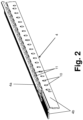
- Figure 2 shows in a perspective view a strip part 4 as installed in the module according to Fig. 1 .
- the strip part 4 has three legs, wherein the guide leg 4a and two further mounting legs 4b are each inclined with respect to one another and each have a freely projecting outer edge.
- the outer edge of the guide leg 4a is rounded.
- the guide leg 4a is formed by folding.
- Each mounting leg 4b has a plurality of screw holes 10.
- the guide leg 4a has a plurality of recesses 11.
- the strip part 4 is configured to be Y-shaped in cross-section.
- Figure 3 shows a slide-in compartment 14a for receiving a module, comprising a receiving opening 15, a compartment base 16 and a roof 16.
- the compartment base 16 and the roof 16 are configured as identical components.
- At least one side wall 17 is provided, which has two guide webs 18, wherein a lower guide web 18 is assigned to or facing the compartment base 16 and an upper guide web 18 is assigned to or facing the roof 16.
- the side wall 17 is assigned a wall strip 19 on the compartment base side.
- the side wall 17 is assigned a further wall strip 19 on the roof side.
- the wall strip 19 receives two spring elements 20 which extend in the direction of the interior of the slide-in compartment 14a.
- the spring elements 20 are configured to be rectangular and flat.
- the compartment base 16 has a recess 21 for receiving grid-like parts.
- the slide-in compartment 14a is configured constructively as a metal sleeve which is open at the front.
- the sleeve comprises a bottom sheet as compartment base 16 and a roof sheet as roof 16, wherein the sheets are connected to side walls 17.
- compartment rear wall 22 Located at the rear end of the slide-in compartment 14a is a compartment rear wall 22 which receives components for contacting. If these components for contacting are arranged in a surrounding control panel, this compartment rear wall 22 can however be completely or partially omitted.
- the slide-in compartment 14a described here is formed by a compartment base 16 which is fastened in the control panel.
- the compartment base 16 has large recesses 21 which can receive grid-like parts which are necessary for achieving the type of protection required in each case. Further cut-outs 23 enable a fixing and/or locking of the module in its respective positions.
- These positions are usually the so-called separating position in which a secure separation of the electrical contacts is achieved and the so-called operating position in which a completely connected contacting is achieved.
- U-shaped side walls 17 which are likewise provided with large cut-outs for air circulation and receiving protection-type elements.
- the lateral guidance of the module is taken over by four wall strips 19 which are configured as plastic strips.
- the plastic strips are arranged in each corner of the slide-in compartment 14a. They sit on the short legs of the U-shaped side walls 17 and positively connect the otherwise still loose side walls 17 to the lower compartment base 16 and the upper compartment base 16.
- spring elements 20 can consist of metal or plastic. They are used for lateral compensation of the tolerance of the modules. Specifically eight spring elements 20 are provided in a slide-in compartment 14a.
- the spring elements 20 are made of metal, they assist the earthing of the modules. Further functions of the plastic strips are the fixing of the grid-like parts 24 to achieve the type of protection in the lateral direction and the fastening of a counterpiece for mechanical coding of the modules.
- the housing 14 in which the slide-in compartments 14a are arranged or configured is not restricted to a configuration as a switchgear cabinet but can be configured as any container or shelf into which modules can be slid.
- the module according to Fig. 1 is configured in this respect as slide-in module and configured in the manner of a drawer.
- Base body 1 Base body 2 Front wall 3 Rear wall 4 Strip part 4a Guide leg 4b Mounting leg 5 Actuating device for switching elements 6 Actuating device for locking system 7 Handle element 8 Operating and display panel 9 Transverse strut 10 Screw hole 11 Recess 12 Electrical device 14 Housing 14a Slide-in compartment 15 Receiving opening 16 Compartment base, roof 17 Side wall 18 Guide web of 17 19 Wall strip 20 Spring element 21 Recess 22 Compartment rear wall 23 Cut-out 24 Grid-like part
Landscapes
- Engineering & Computer Science (AREA)
- Power Engineering (AREA)
- Casings For Electric Apparatus (AREA)
- Microelectronics & Electronic Packaging (AREA)
Claims (6)
- Logement, comprenant un compartiment d'encastrement (14a) destiné à recevoir un module, le compartiment d'encastrement comprenant une ouverture de réception (15), une base de compartiment (16) et un haut (16), dans lequel la base de compartiment (16) et le haut (16) sont configurés sous forme de composants identiques, dans lequel au moins une paroi latérale (17) est prévue, qui a deux nervures de guidage (18), dans lequel une nervure de guidage (18) est destinée à servir de contre-élément de guidage pour le module et dans lequel une nervure de guidage inférieure (18) est attribuée, ou fait face, à la base de compartiment (16) et une nervure de guidage supérieure (18) est attribuée, ou fait face, au haut (16), dans lequel, à la paroi latérale (17), est attribuée une bande de paroi (19) sur le côté base de compartiment et, à la paroi latérale (17), est attribuée une bande de paroi (19) sur le côté haut, dans lequel une bande de paroi (19) est destinée à servir de contre-élément de guidage pour le module,
caractérisé en ce que
chaque bande de paroi (19) reçoit deux éléments ressorts (20), qui s'étendent dans la direction de l'intérieur du compartiment d'encastrement (14a), et dans lequel les éléments ressorts (20) sont destinés à compenser une tolérance latérale du module. - Logement selon la revendication 1, caractérisé en ce que la base de compartiment (16) a un évidement (21) destiné à recevoir des parties de type grille.
- Agencement, comprenant un logement selon la revendication 1 ou 2 et un module destiné à être inséré dans le logement (14) ou destiné à être retiré du logement (14), dans lequel le module comprend un corps de base (1) ayant une paroi avant (2) et une paroi arrière (3), dans lequel des parties de bande (4) oblongues parallèles s'étendent entre la paroi avant (2) et la paroi arrière (3), l'extension longitudinale de celles-ci espace l'une de l'autre la paroi avant (2) et la paroi arrière (3), et dans lequel au moins une partie de bande (4) a un segment de guidage (4a) pour coopération avec un contre-élément de guidage (13).
- Agencement selon la revendication 3, caractérisé en ce que les segments de guidage (4a) font saillie librement vers l'extérieur avec un bord extérieur et/ou que la partie de bande (4) a seulement un segment de guidage (4a).
- Agencement selon la revendication 3 ou 4, caractérisé en ce que la partie de bande (4) a trois segments, dans lequel le segment de guidage (4a) et deux segments de montage supplémentaires (4b) sont chacun inclinés les uns par rapport aux autres et ont un bord extérieur saillant.
- Agencement selon l'une quelconque des revendications 3 à 5, caractérisé en ce que la partie de bande (4) est configurée pour être en forme de Y en section transversale.
Applications Claiming Priority (1)
| Application Number | Priority Date | Filing Date | Title |
|---|---|---|---|
| PCT/EP2018/058620 WO2019192689A1 (fr) | 2018-04-04 | 2018-04-04 | Compartiment pour module amovible |
Publications (3)
| Publication Number | Publication Date |
|---|---|
| EP3776764A1 EP3776764A1 (fr) | 2021-02-17 |
| EP3776764C0 EP3776764C0 (fr) | 2025-01-22 |
| EP3776764B1 true EP3776764B1 (fr) | 2025-01-22 |
Family
ID=61952691
Family Applications (1)
| Application Number | Title | Priority Date | Filing Date |
|---|---|---|---|
| EP18716992.5A Active EP3776764B1 (fr) | 2018-04-04 | 2018-04-04 | Compartiment pour module d'insertion |
Country Status (4)
| Country | Link |
|---|---|
| US (1) | US11329458B2 (fr) |
| EP (1) | EP3776764B1 (fr) |
| CN (1) | CN111903023B (fr) |
| WO (1) | WO2019192689A1 (fr) |
Families Citing this family (4)
| Publication number | Priority date | Publication date | Assignee | Title |
|---|---|---|---|---|
| WO2019192689A1 (fr) | 2018-04-04 | 2019-10-10 | Abb Schweiz Ag | Compartiment pour module amovible |
| WO2019192690A1 (fr) * | 2018-04-04 | 2019-10-10 | Abb Schweiz Ag | Système comprenant un compartiment et un module coulissant |
| FR3121290B1 (fr) | 2021-03-26 | 2024-03-29 | Schneider Electric Ind Sas | Caisson de supportage, armoire électrique de raccordement comprenant un tel caisson de supportage et procédé d’assemblage d’une telle armoire électrique |
| CN223436852U (zh) * | 2024-09-10 | 2025-10-14 | 施耐德(西安)创新技术有限公司 | 电气柜 |
Family Cites Families (21)
| Publication number | Priority date | Publication date | Assignee | Title |
|---|---|---|---|---|
| FR1518815A (fr) * | 1967-02-06 | 1968-03-29 | Telemecanique Electrique | Tableau électrique à tiroirs débrochables |
| FR2082369A5 (fr) | 1970-03-12 | 1971-12-10 | Comp Generale Electricite | |
| KR200155605Y1 (ko) * | 1996-08-13 | 1999-09-01 | 한상준 | Mcc용 유니트의 슬라이드 장치 |
| GB2322274B (en) * | 1997-02-17 | 1999-01-13 | Strix Ltd | Controls for electric heaters |
| DE29909433U1 (de) | 1999-05-29 | 1999-07-22 | Weyler-Kompensationssysteme GmbH, 53639 Königswinter | Schaltgeräteschrank |
| DE20013226U1 (de) * | 2000-07-21 | 2000-12-07 | Siemens AG, 80333 München | Einrichtung mit Führungselementen zur Ausrichtung einfahrbarer Niederspannungs-Leistungsschalter im Einschubrahmen |
| EP1249750A1 (fr) * | 2001-04-12 | 2002-10-16 | Lufthansa Technik AG | Cadre du rack |
| JPWO2003036772A1 (ja) * | 2001-10-25 | 2005-02-17 | 三菱電機株式会社 | コントロールセンタ |
| US7417848B2 (en) * | 2005-11-11 | 2008-08-26 | Rockwell Automation Technologies, Inc. | Multiple height, high density horizontal low voltage motor control center |
| US7419394B2 (en) * | 2005-11-11 | 2008-09-02 | Rockwell Automation Technologies, Inc. | Electrical system having withdrawable unit with maintained control and communication connection |
| US8047383B2 (en) * | 2005-11-29 | 2011-11-01 | Foundry Networks, Llc | Rackmount system including conversion rail |
| DE102006058778B4 (de) * | 2006-12-12 | 2013-04-25 | Rittal Gmbh & Co. Kg | Schaltschrankanordnung |
| JP5578213B2 (ja) * | 2012-08-30 | 2014-08-27 | 株式会社安川電機 | 搬出入装置 |
| CN102889745B (zh) * | 2012-10-24 | 2015-01-07 | 海尔集团公司 | 夹紧装置 |
| US9337596B2 (en) * | 2014-07-14 | 2016-05-10 | Rockwell Automation Technologies, Inc. | Systems and methods for aligning a ground stab |
| JP6392974B2 (ja) * | 2014-08-13 | 2018-09-19 | 簡利宸 | 引き出しの配置が自在な物入れ |
| DE102015105482B4 (de) * | 2015-04-10 | 2019-02-07 | Rittal Gmbh & Co. Kg | Schaltschrank oder Rack zur Aufnahme elektrischer Energiespeicher, insbesondere Batterien, und eine entsprechende Schaltschrank- oder Rackanordnung |
| KR200484532Y1 (ko) * | 2016-02-26 | 2017-10-10 | 엘에스산전 주식회사 | 모터 컨트롤 센터 |
| WO2019192689A1 (fr) | 2018-04-04 | 2019-10-10 | Abb Schweiz Ag | Compartiment pour module amovible |
| WO2019192688A1 (fr) * | 2018-04-04 | 2019-10-10 | Abb Schweiz Ag | Module amovible |
| WO2019192690A1 (fr) * | 2018-04-04 | 2019-10-10 | Abb Schweiz Ag | Système comprenant un compartiment et un module coulissant |
-
2018
- 2018-04-04 WO PCT/EP2018/058620 patent/WO2019192689A1/fr not_active Ceased
- 2018-04-04 CN CN201880091978.XA patent/CN111903023B/zh active Active
- 2018-04-04 EP EP18716992.5A patent/EP3776764B1/fr active Active
-
2020
- 2020-10-01 US US17/060,090 patent/US11329458B2/en active Active
Also Published As
| Publication number | Publication date |
|---|---|
| US20210021108A1 (en) | 2021-01-21 |
| EP3776764A1 (fr) | 2021-02-17 |
| EP3776764C0 (fr) | 2025-01-22 |
| US11329458B2 (en) | 2022-05-10 |
| WO2019192689A1 (fr) | 2019-10-10 |
| CN111903023A (zh) | 2020-11-06 |
| CN111903023B (zh) | 2024-09-06 |
Similar Documents
| Publication | Publication Date | Title |
|---|---|---|
| US11322917B2 (en) | Arrangement comprising a compartment and a slide-in module | |
| US11329458B2 (en) | Compartment for a withdrawable module | |
| US7826201B2 (en) | Control box arrangement | |
| US4710853A (en) | Assembly for mounted components with snap-action | |
| US8283576B2 (en) | Hinges for control box enclosure | |
| US6205017B1 (en) | Switchgear assembly with front accessible slide-in fixed power switch | |
| US7924550B2 (en) | Multiphase line fuse module | |
| CN101542858A (zh) | 开关柜装置 | |
| EP3454436B1 (fr) | Dispositif de partitionnement de compartiment et de support de barres omnibus dans une armoire de distribution électrique basse tension | |
| US20170207607A1 (en) | Distributing panel | |
| BR102018068346A2 (pt) | Quadro de distribuição elétrica de baixa tensão | |
| US7616431B2 (en) | Electrical enclosure and support assembly therefor | |
| US8810998B2 (en) | Motor control center and communication system therefor | |
| US8210362B2 (en) | Control box arrangement | |
| US20170250526A1 (en) | Motor control center | |
| KR960003006A (ko) | 폐쇄배전반의 폐쇄상자 및 이를 사용한 페쇄배전반의 조립방법 | |
| EP3776766B1 (fr) | Module amovible | |
| EP2912735B1 (fr) | Ensemble barre omnibus | |
| US20190252865A1 (en) | Electrical Unit for a Motor Control Center with Ingress Protection | |
| EP1835587A1 (fr) | Boîte pour enceinte de tableau | |
| CN113964692A (zh) | 一种基于电动控制隔离开关的高压电气柜 | |
| HU216927B (hu) | Kisfeszültségű kapcsolóberendezés villamos energia átadására vagy elosztására | |
| KR100987288B1 (ko) | 전력회로차단기의 스위칭 장치 | |
| US6474479B2 (en) | Module rack having at least one front facing groove for mounting components thereto | |
| EP0353202B1 (fr) | Système d'éléments modulaires pour monter des panneaux électriques, particulièrement du type basse tension |
Legal Events
| Date | Code | Title | Description |
|---|---|---|---|
| STAA | Information on the status of an ep patent application or granted ep patent |
Free format text: STATUS: UNKNOWN |
|
| STAA | Information on the status of an ep patent application or granted ep patent |
Free format text: STATUS: THE INTERNATIONAL PUBLICATION HAS BEEN MADE |
|
| PUAI | Public reference made under article 153(3) epc to a published international application that has entered the european phase |
Free format text: ORIGINAL CODE: 0009012 |
|
| STAA | Information on the status of an ep patent application or granted ep patent |
Free format text: STATUS: REQUEST FOR EXAMINATION WAS MADE |
|
| 17P | Request for examination filed |
Effective date: 20201005 |
|
| AK | Designated contracting states |
Kind code of ref document: A1 Designated state(s): AL AT BE BG CH CY CZ DE DK EE ES FI FR GB GR HR HU IE IS IT LI LT LU LV MC MK MT NL NO PL PT RO RS SE SI SK SM TR |
|
| AX | Request for extension of the european patent |
Extension state: BA ME |
|
| DAV | Request for validation of the european patent (deleted) | ||
| DAX | Request for extension of the european patent (deleted) | ||
| STAA | Information on the status of an ep patent application or granted ep patent |
Free format text: STATUS: EXAMINATION IS IN PROGRESS |
|
| 17Q | First examination report despatched |
Effective date: 20220817 |
|
| GRAP | Despatch of communication of intention to grant a patent |
Free format text: ORIGINAL CODE: EPIDOSNIGR1 |
|
| STAA | Information on the status of an ep patent application or granted ep patent |
Free format text: STATUS: GRANT OF PATENT IS INTENDED |
|
| RIC1 | Information provided on ipc code assigned before grant |
Ipc: H02B 1/36 20060101ALN20241007BHEP Ipc: H02B 1/34 20060101AFI20241007BHEP |
|
| INTG | Intention to grant announced |
Effective date: 20241021 |
|
| GRAS | Grant fee paid |
Free format text: ORIGINAL CODE: EPIDOSNIGR3 |
|
| GRAA | (expected) grant |
Free format text: ORIGINAL CODE: 0009210 |
|
| STAA | Information on the status of an ep patent application or granted ep patent |
Free format text: STATUS: THE PATENT HAS BEEN GRANTED |
|
| AK | Designated contracting states |
Kind code of ref document: B1 Designated state(s): AL AT BE BG CH CY CZ DE DK EE ES FI FR GB GR HR HU IE IS IT LI LT LU LV MC MK MT NL NO PL PT RO RS SE SI SK SM TR |
|
| REG | Reference to a national code |
Ref country code: GB Ref legal event code: FG4D |
|
| REG | Reference to a national code |
Ref country code: CH Ref legal event code: EP |
|
| REG | Reference to a national code |
Ref country code: IE Ref legal event code: FG4D |
|
| REG | Reference to a national code |
Ref country code: DE Ref legal event code: R096 Ref document number: 602018078654 Country of ref document: DE |
|
| U01 | Request for unitary effect filed |
Effective date: 20250122 |
|
| U07 | Unitary effect registered |
Designated state(s): AT BE BG DE DK EE FI FR IT LT LU LV MT NL PT RO SE SI Effective date: 20250128 |
|
| U20 | Renewal fee for the european patent with unitary effect paid |
Year of fee payment: 8 Effective date: 20250425 |
|
| PG25 | Lapsed in a contracting state [announced via postgrant information from national office to epo] |
Ref country code: RS Free format text: LAPSE BECAUSE OF FAILURE TO SUBMIT A TRANSLATION OF THE DESCRIPTION OR TO PAY THE FEE WITHIN THE PRESCRIBED TIME-LIMIT Effective date: 20250422 |
|
| PG25 | Lapsed in a contracting state [announced via postgrant information from national office to epo] |
Ref country code: PL Free format text: LAPSE BECAUSE OF FAILURE TO SUBMIT A TRANSLATION OF THE DESCRIPTION OR TO PAY THE FEE WITHIN THE PRESCRIBED TIME-LIMIT Effective date: 20250122 |
|
| PG25 | Lapsed in a contracting state [announced via postgrant information from national office to epo] |
Ref country code: ES Free format text: LAPSE BECAUSE OF FAILURE TO SUBMIT A TRANSLATION OF THE DESCRIPTION OR TO PAY THE FEE WITHIN THE PRESCRIBED TIME-LIMIT Effective date: 20250122 |
|
| PG25 | Lapsed in a contracting state [announced via postgrant information from national office to epo] |
Ref country code: IS Free format text: LAPSE BECAUSE OF FAILURE TO SUBMIT A TRANSLATION OF THE DESCRIPTION OR TO PAY THE FEE WITHIN THE PRESCRIBED TIME-LIMIT Effective date: 20250522 Ref country code: NO Free format text: LAPSE BECAUSE OF FAILURE TO SUBMIT A TRANSLATION OF THE DESCRIPTION OR TO PAY THE FEE WITHIN THE PRESCRIBED TIME-LIMIT Effective date: 20250422 |
|
| PG25 | Lapsed in a contracting state [announced via postgrant information from national office to epo] |
Ref country code: HR Free format text: LAPSE BECAUSE OF FAILURE TO SUBMIT A TRANSLATION OF THE DESCRIPTION OR TO PAY THE FEE WITHIN THE PRESCRIBED TIME-LIMIT Effective date: 20250122 |
|
| PG25 | Lapsed in a contracting state [announced via postgrant information from national office to epo] |
Ref country code: GR Free format text: LAPSE BECAUSE OF FAILURE TO SUBMIT A TRANSLATION OF THE DESCRIPTION OR TO PAY THE FEE WITHIN THE PRESCRIBED TIME-LIMIT Effective date: 20250423 |
|
| PG25 | Lapsed in a contracting state [announced via postgrant information from national office to epo] |
Ref country code: SM Free format text: LAPSE BECAUSE OF FAILURE TO SUBMIT A TRANSLATION OF THE DESCRIPTION OR TO PAY THE FEE WITHIN THE PRESCRIBED TIME-LIMIT Effective date: 20250122 |
|
| PG25 | Lapsed in a contracting state [announced via postgrant information from national office to epo] |
Ref country code: CZ Free format text: LAPSE BECAUSE OF FAILURE TO SUBMIT A TRANSLATION OF THE DESCRIPTION OR TO PAY THE FEE WITHIN THE PRESCRIBED TIME-LIMIT Effective date: 20250122 |
|
| PG25 | Lapsed in a contracting state [announced via postgrant information from national office to epo] |
Ref country code: SK Free format text: LAPSE BECAUSE OF FAILURE TO SUBMIT A TRANSLATION OF THE DESCRIPTION OR TO PAY THE FEE WITHIN THE PRESCRIBED TIME-LIMIT Effective date: 20250122 |
|
| U1N | Appointed representative for the unitary patent procedure changed after the registration of the unitary effect |
Representative=s name: ZIMMERMANN & PARTNERPATENTANWAELTE MBB; DE |
|
| REG | Reference to a national code |
Ref country code: CH Ref legal event code: H13 Free format text: ST27 STATUS EVENT CODE: U-0-0-H10-H13 (AS PROVIDED BY THE NATIONAL OFFICE) Effective date: 20251125 |
|
| PLBE | No opposition filed within time limit |
Free format text: ORIGINAL CODE: 0009261 |
|
| STAA | Information on the status of an ep patent application or granted ep patent |
Free format text: STATUS: NO OPPOSITION FILED WITHIN TIME LIMIT |
|
| PG25 | Lapsed in a contracting state [announced via postgrant information from national office to epo] |
Ref country code: MC Free format text: LAPSE BECAUSE OF FAILURE TO SUBMIT A TRANSLATION OF THE DESCRIPTION OR TO PAY THE FEE WITHIN THE PRESCRIBED TIME-LIMIT Effective date: 20250122 |
|
| GBPC | Gb: european patent ceased through non-payment of renewal fee |
Effective date: 20250422 |
|
| 26N | No opposition filed |
Effective date: 20251023 |
|
| PG25 | Lapsed in a contracting state [announced via postgrant information from national office to epo] |
Ref country code: GB Free format text: LAPSE BECAUSE OF NON-PAYMENT OF DUE FEES Effective date: 20250422 |
|
| PG25 | Lapsed in a contracting state [announced via postgrant information from national office to epo] |
Ref country code: CH Free format text: LAPSE BECAUSE OF NON-PAYMENT OF DUE FEES Effective date: 20250430 |
|
| PG25 | Lapsed in a contracting state [announced via postgrant information from national office to epo] |
Ref country code: IE Free format text: LAPSE BECAUSE OF NON-PAYMENT OF DUE FEES Effective date: 20250404 |