EP3776843B1 - Élément de couverture de toit, élément de couverture de toit solaire, assemblage d'éléments de couverture de toit solaires et procédé de fabrication pour un élément de couverture de toit solaire - Google Patents
Élément de couverture de toit, élément de couverture de toit solaire, assemblage d'éléments de couverture de toit solaires et procédé de fabrication pour un élément de couverture de toit solaire Download PDFInfo
- Publication number
- EP3776843B1 EP3776843B1 EP19722501.4A EP19722501A EP3776843B1 EP 3776843 B1 EP3776843 B1 EP 3776843B1 EP 19722501 A EP19722501 A EP 19722501A EP 3776843 B1 EP3776843 B1 EP 3776843B1
- Authority
- EP
- European Patent Office
- Prior art keywords
- roof covering
- plug
- solar
- contact means
- covering element
- Prior art date
- Legal status (The legal status is an assumption and is not a legal conclusion. Google has not performed a legal analysis and makes no representation as to the accuracy of the status listed.)
- Active
Links
Images


Classifications
-
- H—ELECTRICITY
- H02—GENERATION; CONVERSION OR DISTRIBUTION OF ELECTRIC POWER
- H02S—GENERATION OF ELECTRIC POWER BY CONVERSION OF INFRARED RADIATION, VISIBLE LIGHT OR ULTRAVIOLET LIGHT, e.g. USING PHOTOVOLTAIC [PV] MODULES
- H02S20/00—Supporting structures for PV modules
- H02S20/20—Supporting structures directly fixed to an immovable object
- H02S20/22—Supporting structures directly fixed to an immovable object specially adapted for buildings
- H02S20/23—Supporting structures directly fixed to an immovable object specially adapted for buildings specially adapted for roof structures
- H02S20/25—Roof tile elements
-
- H—ELECTRICITY
- H02—GENERATION; CONVERSION OR DISTRIBUTION OF ELECTRIC POWER
- H02S—GENERATION OF ELECTRIC POWER BY CONVERSION OF INFRARED RADIATION, VISIBLE LIGHT OR ULTRAVIOLET LIGHT, e.g. USING PHOTOVOLTAIC [PV] MODULES
- H02S40/00—Components or accessories in combination with PV modules, not provided for in groups H02S10/00 - H02S30/00
- H02S40/30—Electrical components
- H02S40/34—Electrical components comprising specially adapted electrical connection means to be structurally associated with the PV module, e.g. junction boxes
-
- Y—GENERAL TAGGING OF NEW TECHNOLOGICAL DEVELOPMENTS; GENERAL TAGGING OF CROSS-SECTIONAL TECHNOLOGIES SPANNING OVER SEVERAL SECTIONS OF THE IPC; TECHNICAL SUBJECTS COVERED BY FORMER USPC CROSS-REFERENCE ART COLLECTIONS [XRACs] AND DIGESTS
- Y02—TECHNOLOGIES OR APPLICATIONS FOR MITIGATION OR ADAPTATION AGAINST CLIMATE CHANGE
- Y02B—CLIMATE CHANGE MITIGATION TECHNOLOGIES RELATED TO BUILDINGS, e.g. HOUSING, HOUSE APPLIANCES OR RELATED END-USER APPLICATIONS
- Y02B10/00—Integration of renewable energy sources in buildings
- Y02B10/10—Photovoltaic [PV]
-
- Y—GENERAL TAGGING OF NEW TECHNOLOGICAL DEVELOPMENTS; GENERAL TAGGING OF CROSS-SECTIONAL TECHNOLOGIES SPANNING OVER SEVERAL SECTIONS OF THE IPC; TECHNICAL SUBJECTS COVERED BY FORMER USPC CROSS-REFERENCE ART COLLECTIONS [XRACs] AND DIGESTS
- Y02—TECHNOLOGIES OR APPLICATIONS FOR MITIGATION OR ADAPTATION AGAINST CLIMATE CHANGE
- Y02E—REDUCTION OF GREENHOUSE GAS [GHG] EMISSIONS, RELATED TO ENERGY GENERATION, TRANSMISSION OR DISTRIBUTION
- Y02E10/00—Energy generation through renewable energy sources
- Y02E10/50—Photovoltaic [PV] energy
Definitions
- the invention relates to a roof covering element, a solar roof covering element, an arrangement of solar roof covering elements and a manufacturing method for a solar roof covering element
- Solar roof covering elements are known in the prior art. These consist of a flat base body formed, for example, by a roof tile or a roof slab, a solar module made of silicon-based solar cells, and a glass pane or plastic layer forming the weather-resistant roof covering.
- the advantage of using such solar roof covering elements, which directly form the roof covering, to create a solar roof system is their structurally simple and aesthetically pleasing integration into the existing roof structure without the need for separate support systems or elements.
- the DE 10 2012 008 852 A1 and the priority claiming WO 2013/167110 A1 disclose a roof tile with a plate-shaped base body made of cast material and a solar module arranged thereon, wherein the base body has at least two holes in which cables are guided. Electrical cables are guided through the holes of the base body, which are preferably already provided with contacts before the feedthrough and which are connected to the solar matrix of the solar module. A specific design or manufacture of this connection is not specified by the DE 10 2012 008 852 A1 or the WO 2013/167110 A1 not suggested. To create an arrangement of several roof tiles, it is suggested that they be connected to each other via a parallel circuit, whereby simple plug contacts can be used.
- DE 197 04 255 A1 discloses a solar roof tile, consisting of a roof tile and interconnected solar cells positioned recessed in the roof tile, with connecting contacts, whose water vapor diffusion-tight contact is made on the back of the roof tile.
- two contact wires extending from the solar cells protrude into the roof tile through a through hole. From the back of the roof tile, permanent contact with the wires is possible via a plug or contact block.
- the DE 197 04 255 A1 The disclosed contacting is disadvantageous in that the insertion of relatively thin, dimensionally unstable contact wires into corresponding receptacles of the plug or contact block attached to the back of the roof tile or partially inserted into the hole must be ensured within the through-hole.
- the production of such a plug connection requires a high level of manufacturing precision to ensure a secure connection with the plug or contact block without the contact wires becoming bent. In automated production, this requires a high level of positioning precision in the approach paths and simultaneously limits the possible production speed.
- the design as a purely physical plug connection has the disadvantage that even small manufacturing tolerances lead to errors in the plug connection or its load-bearing capacity and durability. In particular, high temperatures in summer due to strong sunlight and high loads can lead to This can lead to significant material aging and resulting connector failures. This can cause high contact resistance in the connectors, which can lead to cable damage or smoldering fires.
- the WO 2013/046195 A1 or the document US 2014/041715 A1 discloses a composite insulation panel with a photovoltaic module arranged on an upper side of the composite insulation panel, having a flat base body and an opening running perpendicular to its base surface, in which two electrical lines are guided from the underside through the opening in a common plug-in socket, wherein the plug-in socket is fastened to the underside of the base body by screwing or gluing.
- a separate connection socket with contact means is pressed into the opening and the contact means of the connection socket are each connected to the lines of the plug-in socket by plug connections.
- the construction comprises a relatively large number of separate individual parts and requires the production of a cable connection within the opening as part of the manufacturing process, which necessitates a correspondingly high level of manufacturing precision for the individual parts and the manufacturing process.
- the fastening of the separate components and the separate production of the electrical connection require a relatively complex and expensive manufacturing process.
- a roof covering element and a solar roof covering element for a solar roof system are to be provided that can be manufactured using a cost-effective, large-scale production process and that enable simple and cost-effective roof installation.
- the core of the invention is a roof covering element with a flat base body, the upper side of which has a receiving surface for a solar module and which has an opening or bore running perpendicular to its base surface, through which at least two electrical lines are led together and in which the lines on the upper side of the base body in the area of the receiving surface are arranged as Contact means end which are held in a common flat connection base or guided so as to be axially movable, wherein the electrical lines are guided in a common plug-in base from the underside through the opening or bore, and the plug-in base is held on the underside of the base body in the axial insertion direction by a plug-in flange in a form-fitting manner and on the top side of the base body against its axial insertion direction by a locking means in a form-fitting and/or force-fitting manner and forms the connection base on the top side of the base body.
- a base body is understood to mean any flat structural element with which a sufficiently stable roof covering can be produced and which can be formed with a receiving surface for a solar module, for example roof tiles, roof stones or roof shingles made of clay, stone, concrete, cement, metal, glass, bitumen, plastic, wood or an organic or inorganic fibre composite material.
- flat means that the base body has a greater area than it does height.
- a support surface is understood to be an area on the upper side of the base body, whose length and width can be defined, on which a solar module can be arranged and mounted.
- the surface of the base body can be flat or curved in the area of the support surface, for example, in the case of a brick-shaped base body with a wave profile.
- a solar module is understood to mean all electrical components with which sunlight can be directly converted into electrical energy, in particular photovoltaic modules consisting of one or more silicon or thin-film solar cells.
- the solar module can be designed as a component with a flat body, for example, a plate-shaped cuboid, but also as a body with curved surfaces, for example, a wave profile.
- the electrical cables serve to transport electrical energy and, if necessary, also to transmit signals. They can be designed either as a common multi-core cable or as a bundle of several single-core cables.
- the wires form at least two contact elements in the terminal base, which represent the two electrical poles required to establish a current flow.
- the base body is easy to manufacture with a single opening or bore perpendicular to its base surface. Since all electrical connections are arranged on the top side of the base body in a common flat terminal base as a contact element, a simple electrical connection to a solar module positioned on the support surface is made possible by means of a cost-effective, large-scale production process.
- the electrical lines are guided in a common plug-in base from the underside through the opening or bore, wherein the plug-in base is held on the underside of the base body in the axial insertion direction by a plug-in flange and on the top side of the base body against its axial insertion direction by a locking means in a form-fitting and/or force-fitting manner, and forms the connection base on the top side of the base body.
- the plug-in base is designed together with the connection base as a one-piece component or as a prefabricated component assembly. This enables the electrical lines to be passed through the base body in a stable manner and is easy to manufacture as part of the production process.
- this enables the roof covering element to be manufactured with relatively large manufacturing tolerances, for example in the dimensioning of the opening or bore, since the plug-in base and the connection base are held stably in the base body by the plug-in flange arranged on the underside of the base body and the locking means arranged on the top of the base body.
- a sealing element is arranged between the plug-in flange and the underside of the base body.
- the sealing element can be a hardening or permanently elastic material, such as rubber, silicone, or an elastomer.
- the plug-in flange is held on the top side of the base body by a clamp or a snap ring as a locking device.
- the locking means is a hollow element which is formed with a retaining flange on the upper side of the base body acting against the axial insertion direction of the plug-in base and which is connected by an inner link in a form-fitting or form-fitting and force-fitting manner to a corresponding outer link of the This allows the plug-in base to be locked by placing the hollow element against the axial insertion direction of the plug-in base.
- the hollow element is an outer sleeve that engages a corresponding plug-in section of the plug-in base with a screw connection or a plug-and-turn connection (bayonet lock).
- the plug-in base is locked by placing the hollow element against the axial insertion direction of the plug-in base in a screwing or plug-and-turn movement.
- the hollow element consists of an outer sleeve slotted in the axial insertion direction, which engages with a corresponding insertion section of the plug-in base in a locking manner.
- the plug-in base is locked by placing the hollow element against the axial insertion direction of the plug-in base in a plug-in movement, whereby the outer sleeve engages the insertion section.
- a sealing element is arranged on the top of the holding flange.
- a simple mechanical electrical connection to a solar module positioned on the support surface is made possible by a cost-effective, mass-production-capable manufacturing process in that the contact elements protrude from the connection base and are guided within it with spring loading against the insertion direction.
- a stable electrical connection is thus easily achieved by creating a combined positive and non-positive connection of corresponding contacts against the spring load.
- the creation of a fixed electrical connection with a solar module positioned on the support surface by means of a cost-effective mass-production The manufacturing process is easily achieved by holding the contact elements firmly in the terminal base or with axial deformation play. This ensures, for example, the easy production of a soldered connection on the top side of the base body.
- the contact elements are formed from a solder material or coated with a solder coating.
- the creation of a permanent electrical connection with a solar module positioned on the support surface is easily made possible by means of a cost-effective, large-scale production process in that the plug-in base is designed with one or two insertion channels for a soldering tool, which is or are accessible via an access opening on the underside of the plug-in base and via which contact can be made with the contact means.
- the soldering of the roof covering element is possible from the underside of the base body and the plug-in base.
- the soldering tool can be brought into direct physical contact with the contact means. After soldering, the insertion channel or channels are closed with a sealant to ensure the electrical insulation of the contact means and to protect them from external weather influences.
- the insertion channel or channels are not open at the upper end, but end or end at their upper end at an effective distance from the contact means.
- the roof covering element is soldered from the underside of the base body and the plug-in base using an induction soldering tool.
- the effective distance of the upper end of the insertion channel(s) is selected such that sufficient energy is applied to the contact elements by an induction soldering tool inserted into the insertion channel. Since the insertion channel(s) is/are not open at the upper end, the electrical insulation and weather protection of the contact elements are ensured.
- the cables terminate on the underside of the base body or below the underside at a distance from it as contacts in a multi-pin connector.
- the cables form at least two contacts in the connector, which represent the two electrical poles required to establish a current flow.
- the cables can be easily and flexibly connected to other components of a solar roof system via the connector.
- the cables In order to be able to overcome a connection distance if necessary without the need for an extension cable, the cables only terminate at a distance from the underside as contacts in the connector.
- the cables are initially led out of the opening or hole or, if one is provided, out of the plug-in base as a common cable, with the cable being formed at its end with the multi-pin connector.
- a simple electrical connection test for the roof covering element is made possible by providing a capacitor connected between the wires, contacts, or contact elements forming the two electrical poles.
- the presence of the capacitor can be easily determined electrically by measuring an alternating voltage signal.
- Solar modules operate exclusively with direct voltage, for which the capacitor is "invisible” during operation, thus not interfering or hindering. In this way, the desired function (generation of electrical energy based on direct voltage) is not impaired by the measuring function, which is performed via an alternating current signal.
- the number of successfully connected capacitors and thus the number of successfully connected roof covering elements can be easily counted or detected.
- a reverse current diode is arranged in the line or lines representing at least one electrical pole.
- an electrical fault in one of the connected solar modules can cause the remaining solar modules to feed their output current into the defective solar module, which can lead to overheating and trigger a fire.
- a diode is arranged in the line(s) of the roof covering element forming at least one electrical pole in a suitable direction, so that it enables the flow of current (energy output) out of the solar module, but prevents the flow of current into the solar module (energy absorption), ie serves as a backflow preventer.
- the capacitor and/or the reverse current diode is or are arranged within the connector.
- a solar module is arranged on the upper side of the base body, which has back contact means, for example in the form of metal plates, on its side facing the upper side of the base body, which are arranged corresponding to the contact means.
- connection base protrude from the connection base and are spring-loaded in the connection base against the insertion direction
- a stable electrical connection with the solar module is achieved by placing the solar module with the back contact means on the contact means against their spring load and the components are connected to one another.
- the contact elements in the terminal base are held firmly or with axial deformation play, a stable electrical connection to the solar module is achieved by placing the module with the back contact elements onto the contact elements and establishing a soldered connection.
- a soldered connection using a cost-effective, mass-production-capable manufacturing process, either the contact elements, the back contact elements, or both the contact elements and the back contact elements are formed from a solder material or coated with a solder coating.
- the solar module has a cell matrix consisting of several series-connected Solar cells.
- Individual cells are usually available on the market with dimensions of around 15 cm x 15 cm and, under load, usually have a power output with high currents of around 8 A at a low voltage of around 0.5 V.
- a cell matrix with a plurality of smaller cells connected in series a comparable power output with relatively lower currents at a relatively higher voltage is achieved.
- a cell matrix of, for example, 50 to 100 smaller cells connected in series a comparable power output with relatively low currents of around 0.2 A at a higher voltage of around 50 V to 60 V can be achieved compared to conventional individual cells available on the market.
- the format, number and arrangement of the small cells are selected so that the available receiving area of the base body is covered as widely as possible while simultaneously taking into account the desired total voltage.
- Single cells available on the market in common formats can be cut into smaller cells with the desired dimensions - e.g. with a laser - and rearranged and assembled as a cell matrix.
- the top surface of the solar roof covering element which forms the roof skin, is made of a glass pane or a plastic sheet or film. This can also serve as the top surface of the solar module.
- the solar roof covering elements are preferably connected in parallel. This offers the advantage that shading of one or more solar modules—for example, by leaves or dirt—only reduces the system output by the amount of the affected solar module(s). Furthermore, the voltage of the entire system is kept constant regardless of the number of connected solar roof covering elements. The number of connected solar modules only changes the output and current of the entire system. This ensures that the voltage of the solar system can always be kept within the limits of extra-low voltage (voltage range I according to IEC 60449), regardless of the total number of connected solar modules.
- the combination of parallel connection and extra-low voltage operation reduces the costs and complexity of planning and designing the entire system because it is associated with reduced requirements for electrical wiring and the design of electrical cables, connections, and insulation. Finally, this also significantly reduces the risks for the personnel installing and connecting the system. The installation of the solar roof covering elements on the roof can therefore be carried out without the need for specially trained or qualified electrical engineers, for example, even by roofers.
- the available mounting area can therefore only be used with a cell matrix of a maximum of 18 or 20 solar cells connected in series, and thus with a correspondingly lower total voltage per solar module.
- a more favorable, higher total voltage which still lies within the limits of the extra-low voltage, can be achieved by connecting at least two solar roof covering elements in groups in a series circuit and the series-connected solar roof covering element groups are in turn connected in a parallel circuit.
- a structurally simple and effective roof installation is ensured by the fact that the cables of the solar roof covering elements each terminate below the underside of the base body in a multi-pin plug connector, and the solar roof covering elements can be connected to one another in groups via a common multiple plug connector and connected in series.
- the series connection is established by a suitable cable routing inside the multiple plug connector, and the solar roof covering element groups can each be connected to the main cables via the multiple plug connector and connected in parallel.
- the series connection is realized via a suitable internal cable routing in the multiple plug connector.
- a further simplification based on the above embodiment is that the multiple plug-in connectors each engage two different electrical poles of the main lines with two piercing contacts.
- a piercing contact is a contact means with which a permanent contact can be established with the cable line by penetrating the insulation layer and any cable sheath. This can, for example, be a pin that is shot through the cable. It can also be an insulation displacement contact.
- the multiple plug-in connectors each engage with one piercing contact on a positive pole and with the other piercing contact on a negative pole of the main lines.
- the particular advantage of this embodiment is that the main lines can be pre-assembled together as cables with the multiple plug-in connectors and supplied as rolls and processed during the installation of the solar roof system. The multiple connectors can be easily installed using the piercing contacts on a pre-assembled cable without the need to remove the insulation and cable sheathing at the contact points beforehand.
- the solar module is arranged on the receiving surface, whereby a force connection is established between the contact means and the return contact means against the spring load of the contact means.
- the solar module is arranged on the receiving surface, and the common contact surfaces of the contact means and the back contact means are heated to the melting point of the solder, resulting in an energy input through the solar module.
- the heating can be achieved in a structurally simple manner using induction soldering.
- the contact means are held in the connection base firmly or with an axial deformation play and the contact means and/or the back contact means are formed from a solder material or are formed with a solder coating, and wherein the plug-in base is formed with one or two insertion channels for a soldering tool, which is or are accessible via an access opening on the underside of the plug-in base and via which contact can be made with the contact means, the solar module is arranged on the receiving surface and heating of the common contact surfaces of the contact means with the back contact means to the melting point of the solder is effected by a soldering tool inserted into the insertion channel or successively into the insertion channels or by two soldering tools inserted simultaneously in parallel into the insertion channels.
- the soldering of the solar roof covering element from the underside of the base body and the plug-in base can be brought into direct physical contact with the contact means.
- the insertion channel(s) are closed with a sealant after soldering has been completed in order to ensure the electrical insulation of the contact means and to protect them from external weather influences.
- the insertion channel(s) are not open at the upper end, but end(s) at their upper end at an effective distance from the contact means.
- the energy input required for soldering is ensured by an induction soldering tool inserted into the insertion channel or successively into the insertion channels, or by two induction soldering tools inserted simultaneously and in parallel into the insertion channels.
- the effective distance of the upper end of the insertion channel(s) is selected in such a way that a sufficient energy input to the contact means is ensured by an induction soldering tool inserted into the insertion channel. Since the insertion channel(s) are not open at the upper end, the electrical insulation and weather protection of the contact elements is ensured.
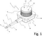
- the Figure 1 shows a perspective view of the plug-in base 1, into which the two-core cable 2 terminates.
- the plug-in base 1 is provided with the kink protection 7, the cuboidal plug-in flange 8, and the conical plug-in section 9. formed.
- the plug-in base 1 is formed with the lamellar outer slot 10.
- the plug-in base 1 forms the flat connection base 11, in which the lines 5 and 6 terminate on the cover surface of the plug-in section 9 as contact means 12 and 13.
- the contact means 12 and 13 form the two electrical poles required to establish a current flow to a solar module.
- the flat seal 14 is arranged on the plug-in flange 8, which is made of foam rubber and has a (in Figure 1 not shown) adhesive coating.
- the Figure 2 shows a perspective view of the route of the cable 2 within the plug-in base 1.
- the lines 5 and 6 are held within the plug-in section 9 by the double clamp 15, which engages the wire insulation 3 and 4.
- the two contact means 12 and 13, each designed as a copper body with a tin coating, are placed on the ends of the lines 5 and 6, which are made of copper wires.
- the contact means 12 and 13 are held in the connection base 11 with a slight axial deformation play, but are otherwise held firmly.
- the slight axial deformation play of the lines 5 and 6 results from the kinked cable routing of the lines 5 and 6 between the double clamp 15 and the contact means 12 and 13 in the plug-in section 9 of the plug-in base 1.
- the contact means 12 and 13 initially protrude slightly from the connection base 11.
- the leads 5 and 6 yield slightly in the area of the lead bends due to deformation.
- This deformation is partly plastic (irreversible) due to further bending of the leads 5 and 6 in the bend area, but partly also elastic (reversible) due to the limited elasticity of the leads 5 and 6 in the bend area.
- Due to the elastic component of the deformation movement a secure contact closure of the contact elements 12 and 13 with the corresponding contacts is ensured by the leads 5 and 6 exerting a slight spring force on the contact connection. This serves to ensure a clean soldered connection between the contact elements 12 and 13 and the corresponding contacts and to practically simplify the production of the soldered connection.
- the Figure 3 shows the plug-in base 1 with the outer sleeve 16 in a perspective exploded view.
- the outer sleeve 16 is designed with axial slots 17, a lamellar inner slot 18 and the retaining flange 19.
- a flat seal 20 is arranged on the retaining flange 19, which is made of foam rubber and has a (in Figure 3 adhesive coating (not shown).
- the (in Figure 3 The adhesive coatings (not shown) of the seals 14 and 20 are each covered with protective films 21 and 21'.
- the segments of the outer sleeve 16 formed by the axial slots 17 serve to encompass the plug-in section 9 of the plug-in base 1.
- the slats of the inner slot 18 of the outer sleeve 16 engage in a locking manner with the slats of the corresponding outer slot 10 of the plug-in section 9.
- the Figure 4 shows the solar module 22 in a partially transparent, perspective view.
- the solar module 22 comprises a cell matrix 23, consisting of a plurality of small solar cells connected in series with one another and a glass pane 24 arranged above it.
- the cell matrix is designed for a power output under full load with currents of approximately 0.2 A at a voltage of 50 V.
- two back contact means 25 and 25' formed from metal plates are arranged on the underside of the solar module 22 and connected to the series connection of the cell matrix 23.
- the back contact means 25 and 25' are each designed as copper bodies with a tin coating.
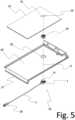
- the Figures 5 to 7 show the solar roof covering element 26 in perspective exploded views.
- Figure 8 shows the finished solar roof covering element 26 in a perspective view.
- the solar module 22 is in the Figures 5 to 8 are shown only schematically; the cell matrix 23 is not shown in each case.
- the solar roof covering element 26 comprises the plug-in base 1, the base body 27, the outer sleeve 16, and the solar module 22.
- the cable 2 of the plug-in base is formed below the underside of the base body 27 at a distance therefrom at its end with the plug-in connector 28.
- the base body 27 is designed as a flat, tile-shaped roof tile.
- the upper side of the base body 27 has a receiving surface 29 for the solar module 22.
- the base body 27 is further formed in the region of the receiving surface 29 with an opening 30 running perpendicular to its base surface.
- the plug-in base 1 is fixed in a workpiece carrier (not shown) so that the connection base 11 is oriented upwards.
- the base body 27 is placed thereon along the insertion axis A so that the insertion section 9 of the plug-in base 1 is received in the opening 30 of the base body 27 and the connection base 11 is arranged approximately at the level of the upper side of the base body 27, as shown in Figure 6 is shown.
- the plug-in socket 1 is held positively on the underside of the base body 27 in the axial insertion direction by the plug-in flange 8.
- the seal 14 for sealing the electrical connection against penetrating moisture from the underside of the base body 27 is arranged between the plug-in flange 8 and the underside of the base body 27.
- the outer sleeve 16 is inserted into the opening 30, wherein the segments of the outer sleeve 16 formed by the axial slots 17 encompass the insertion section 9 of the insertion base 1 and the slats of the inner slot 18 of the outer sleeve 16 engage in a locking manner with the slats of the corresponding outer slot 10 of the insertion section 9.
- the insertion base 1 is held on the upper side of the base body 27 against the axial insertion direction by the holding flange 19 of the outer sleeve 16.
- FIG. 8 2 shows the fully assembled solar roof covering element 26, in which the solar module 22 is placed on the receiving surface 29 of the base body 27.
- the back contact means 25 and 25' are arranged in a form-fitting manner on the contact means 12 and 13, whereby the axial deformation play of the lines 5 and 6 in the plug-in section 9 of the plug-in base 1 ensures a secure contact between the contact means 12 and 13 and the back contact means 25 and 25'.
- the common contact surfaces of the contact means 12, 13 and the back contact means 25, 25' are heated to the melting point of the solder through the solar module using an induction soldering process.
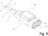
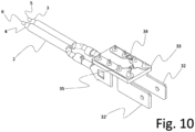
- Figure 9 shows the connector 28, which is formed from an injection-molded housing 31 with a kink protection 7' and in which the lines 5 and 6 end as contacts 32 and 32'.
- Figure 10 shows the internal components of the connector 28, in which the lines 5 and 6 are connected via the circuit board 33 to the contacts 32 and 32'.
- the contacts 32 and 32' represent the two electrical poles required to establish a current flow between the solar module 22 and the other electrical components of a solar roof system.
- the reverse current diode 34 is arranged within the contact of the line 5 on the circuit board 33 as a reverse current barrier for the line 5. This prevents a reverse current into the solar module 22 connected to the line 5.
- the capacitor 35 is arranged between the contacts of the lines 5 and 6 on the circuit board 33.
- a solar module 22 successfully connected via the lines 5 and 6 within a solar roof system can be easily counted or detected using the capacitor 35.
- a suitable capacitor with a capacitance of 0.1 to 100 nF can be used.
- the Figure 11 show the multiple plug-in connector 36, which is designed as a double plug-in connector 36, which consists of an injection-molded housing 31' with bend protectors 7" and 7' and is connected to the plug-in connectors 28 and 28'.
- the double plug-in connector 36 serves to connect the plug-in connectors 28 and 28' to the main lines 5" and 6" of the main cable 2".
- the injection-molded housing 31' of the double plug-in connector 36 has a mounting bracket 37, with which it can be connected to the roof structure during roof installation.
- the mounting bracket 37 can be screwed, nailed, or stapled to components of the roof structure - for example, the roof battens.
- Figure 12 shows the internal components of the double plug-in connection means 36 and the plug connectors 28 and 28'.
- the line 5 of the plug connector 28 is connected to the main line 5" via the circuit board 33, the contact 32 and the piercing contact designed as an insulation displacement contact 38.
- the main line 5" forms the positive contact of the electrical system.
- the line 6 is connected to the Series connection contact 39 is connected and can be connected to line 5' of connector 28' via this and contact 32" and circuit board 33' of connector 28'.
- Line 6' of connector 28' can be connected to main line 6" via circuit board 33', contact 32" and insulation displacement contact 38'.
- the main line 6" forms the negative contact of the electrical system.
- the double plug connection means 36 can be easily configured as a multiple plug connection means, via which correspondingly more roof covering elements can be connected in series with each other in groups.
- Several pairs or groups of solar roof covering elements connected to the main lines 5" and 6" via additional double or multiple plug connection means are connected in parallel with each other via the main lines 5" and 6".
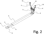
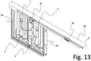
- the Figure 13 shows an arrangement of two solar roof covering elements 26 and 26' in a suspended installation on a roof batten 40.
- the solar roof covering elements 26 and 26' are connected to the main cables 2" via the double plug-in connection means 36 and are connected in series as a pair.
- the plug-in bases 1 and 1' are arranged in such a way that any moisture formed by condensation on the cables 2 and 2' can drip off without penetrating the plug-in bases 1 and 1'.
- a further pair of solar roof covering elements which can be connected to the main lines 5" and 6" via the further double plug-in connection means 36', can be connected in parallel with the solar roof covering element pair 26/26' via the double plug-in connection means 36'.
- the Figure 14 shows a schematic circuit of an arrangement of several solar roof covering elements as a solar roof system.
- the individual solar roof covering elements are connected in pairs via series-connected contacts to the main lines 5" and 6" and are connected in series with each other.
- the solar roof covering elements 26 and 26' and the series connection contact 39 are numbered as examples.
- the individual pairs of solar roof covering elements, each connected in series, are connected in parallel via the series connection contacts and the main lines 5" and 6".
- the overall arrangement is designed for a total voltage of a maximum of 120 V.
- the main lines 5" and 6" are connected to the converter 41, which, depending on the desired functionality and design of the solar roof system, can be, for example, an inverter, an MPP tracker, or a charge controller.
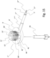
- the Figure 15 shows a perspective, partially transparent view of the plug-in base 1", into which the two-core cable 2′′′ terminates.
- the two electrical lines 5′′′ and 6′′′ are guided within a common cable sheath.
- the plug-in base 1" is designed with the kink protection 7′′′′′′, the round plug-in flange 8', and the conical plug-in section 9'.
- the plug-in base 1" is designed with the lamellar outer slot 10'.
- the plug-in base 1" forms the flat connection base 11', in which the lines 5′′′ and 6′′′ terminate on the cover surface of the plug-in section 9' as contact means 12' and 13'.
- the contact elements 12' and 13' represent the two electrical poles required to establish a current flow to a solar module and are provided with a solder coating.
- the plug-in base 1" is further provided with two internal insertion channels 44 and 44', each accessible via access openings 42, 42' on the underside of the plug-in base 1". At their upper ends, the insertion channels 44 and 44' each terminate at an effective distance from the contact elements 12' and 13'.
- the effective distance is selected such that a finger-shaped induction soldering tool 43, which is inserted into the insertion channels 44 and 44' in a form-fitting manner, ensures sufficient energy input to the contact elements 12' and 13' to melt their solder coating or, in addition, the solder coating of the back contact elements arranged on the contact elements 12' and 13'.
- the induction soldering tool 43 can be inserted successively into the insertion channels 44 and 44' to create a solder connection.
- two induction soldering tools can be inserted simultaneously and in parallel into the insertion channels 44 and 44'.
- the plug-in base 1" can also be designed with a common insertion channel for both contact means 12' and 13'.
- the contact means 12' and 13' are then heated simultaneously by a single appropriately dimensioned induction brazing tool.
Landscapes
- Engineering & Computer Science (AREA)
- Architecture (AREA)
- Civil Engineering (AREA)
- Structural Engineering (AREA)
- Photovoltaic Devices (AREA)
- Roof Covering Using Slabs Or Stiff Sheets (AREA)
Claims (31)
- Élément de couverture de toit comportant un corps de base (27) plat dont le côté supérieur présente une surface de réception (29) pour un module solaire (22) et qui présente une ouverture (30) ou un alésage s'étendant perpendiculairement à sa surface de base, à travers lequel au moins deux câbles (5, 5', 5‴, 6, 6', 6‴) électriques sont guidés conjointement, dans lequel les câbles (5, 5', 5‴, 6, 6', 6‴) se terminent sur le côté supérieur du corps de base (27) dans la zone de la surface de réception (29) sous forme de moyens de contact (12, 12', 13, 13') qui sont maintenus ou guidés de manière à pouvoir se déplacer axialement dans un socle de connexion (11, 11') plat commun,
caractérisé en ce que les câbles (5, 5', 5‴, 6, 6', 6‴) électriques sont guidés dans un socle d'enfichage (1, 1', 1") commun depuis le côté inférieur à travers l'ouverture (30) ou l'alésage, dans lequel le socle d'enfichage (1, 1', 1") est maintenu par complémentarité de forme sur le côté inférieur du corps de base (27) dans la direction d'enfichage axiale par une bride d'enfichage (8, 8') et, sur le côté supérieur du corps de base (27), contre sa direction d'enfichage axiale, est maintenu par complémentarité de forme et/ou par force par un moyen de blocage et forme le socle de connexion (11, 11') sur le côté supérieur du corps de base (27). - Élément de couverture de toit selon la revendication 1,
caractérisé en ce qu'un élément d'étanchéité est agencé entre la bride d'enfichage (8, 8') et le côté inférieur du corps de base (27). - Élément de couverture de toit selon la revendication 1 ou 2,
caractérisé en ce que le moyen de blocage est une agrafe ou une bague d'arrêt ressort. - Élément de couverture de toit selon la revendication 1 ou 2,
caractérisé en ce que le moyen de blocage est un élément creux qui est réalisé avec une bride de maintien (19) agissant sur le côté supérieur du corps de base (27) à l'encontre de la direction d'enfichage axiale du socle d'enfichage (1, 1', 1") et qui vient en prise par complémentarité de forme ou par complémentarité de forme et par force, par une coulisse intérieure (18), avec une coulisse extérieure (10, 10') correspondante du socle d'enfichage (1, 1', 1"). - Élément de couverture de toit selon la revendication 4,
caractérisé en ce que l'élément creux est une douille extérieure (16) qui vient en prise, par un assemblage par vis ou par une connexion par enfichage et rotation, avec une section d'enfichage correspondante du socle d'enfichage. - Élément de couverture de toit selon la revendication 4,
caractérisé en ce que l'élément creux est une douille extérieure (16) fendue dans la direction d'enfichage axiale qui vient en prise par encliquetage avec une section d'enfichage (9, 9') correspondante du socle d'enfichage (1, 1', 1"). - Élément de couverture de toit selon l'une des revendications 4 à 6,
caractérisé en ce qu'un élément d'étanchéité est agencé sur le côté supérieur de la bride de maintien (19). - Élément de couverture de toit selon l'une des revendications 1 à 7,
caractérisé en ce que les moyens de contact (12, 12', 13, 13') font saillie hors du socle de connexion (11) et sont guidés dans celui-ci à l'encontre de la direction d'enfichage par un ressort. - Élément de couverture de toit selon l'une des revendications 1 à 7,
caractérisé en ce que les moyens de contact (12, 12', 13, 13') sont maintenus dans le socle de connexion de manière fixe ou avec un jeu de déformation axial. - Élément de couverture de toit selon la revendication 9,
caractérisé en ce que les moyens de contact (12, 12', 13, 13') sont formés à partir d'un matériau de brasage ou sont réalisés avec un revêtement de brasage. - Élément de couverture de toit selon l'une des revendications 1 à 7, 9 ou 10, caractérisé en ce que le socle d'enfichage (1, 1', 1") est réalisé avec un canal d'insertion ou deux canaux d'insertion (44, 44') pour un outil de brasage, lesquels sont accessibles par l'intermédiaire d'une ouverture d'accès (42, 42') sur le côté inférieur du socle d'enfichage et par l'intermédiaire desquels un contact avec les moyens de contact (12, 12', 13, 13') peut être établi.
- Élément de couverture de toit selon la revendication 11,
caractérisé en ce que le canal d'insertion ou les canaux d'insertion (44, 44') se terminent, au niveau de leur extrémité supérieure, à une distance d'action des moyens de contact (12, 13) et un outil de brasage par induction (43) peut être inséré dans le canal d'insertion ou les canaux d'insertion (44, 44'). - Élément de couverture de toit selon l'une des revendications 1 à 12,
caractérisé en ce que les câbles (5, 5', 5‴, 6, 6', 6‴) se terminent sur le côté inférieur du corps de base (27) ou en dessous du côté inférieur, à une certaine distance dudit corps de base, sous forme de contacts (32, 32', 32", 32‴) dans un connecteur à fiches (28, 28') multipolaire. - Élément de couverture de toit selon l'une des revendications 1 à 13,
caractérisé en ce qu'un condensateur (35) est prévu, lequel est connecté entre les câbles (5, 5', 5‴, 6, 6', 6‴), contacts (32, 32', 32", 32‴) ou moyens de contact (12, 12', 13, 13') formant les deux pôles électriques. - Élément de couverture de toit selon l'une des revendications 1 à 14,
caractérisé en ce qu'une diode de retour de courant (34) est agencée dans le câble ou dans les câbles (5, 5', 5‴, 6, 6', 6‴) formant au moins un pôle électrique. - Élément de couverture de toit selon la revendication 13 et l'une des revendications 14 et/ou 15 ou les deux, caractérisé en ce que le condensateur (35) et/ou la diode de retour de courant (34) sont agencés à l'intérieur du connecteur à fiches (28, 28').
- Élément de couverture de toit solaire (26, 26'), présentant un élément de couverture de toit selon l'une des revendications 1 à 16 et un module solaire (22) agencé sur le côté supérieur du corps de base (27), caractérisé en ce que le module solaire (22) présente des moyens de contact arrière (25, 25') sur son côté tourné vers le côté supérieur du corps de base (27) qui sont agencés de manière à correspondre aux moyens de contact (12, 13).
- Élément de couverture de toit solaire (26, 26') selon la revendication 17, dans lequel les moyens de contact (12, 12', 13, 13') sont maintenus dans le socle de connexion (11, 11') de manière fixe ou avec un jeu de déformation axial,
caractérisé en ce que les moyens de contact arrière (25, 25') sont formés à partir d'un matériau de brasage ou sont réalisés avec un revêtement de brasage. - Élément de couverture de toit solaire (26, 26') selon la revendication 17 ou 18, caractérisé en ce que le module solaire (22) présente une matrice cellulaire (23) composée de plusieurs cellules solaires montées en série.
- Élément de couverture de toit solaire (26, 26') selon la revendication 19,
caractérisé en ce que le format, le nombre et l'agencement des cellules solaires sont choisis de telle sorte que la surface de réception (29) disponible du corps de base (27) est couverte le plus largement possible en tenant compte simultanément de la tension totale souhaitée. - Élément de couverture de toit solaire (26, 26') selon l'une des revendications 17 à 20, caractérisé en ce que son côté supérieur formant la couverture de toit est une vitre en verre (24) ou une vitre ou une feuille en matière plastique.
- Agencement d'éléments de couverture de toit solaire (26, 26') selon l'une des revendications 17 à 21, caractérisé en ce que les éléments de couverture de toit solaire (26, 26') sont connectés entre eux selon un montage en parallèle.
- Agencement d'éléments de couverture de toit solaires (26, 26') selon l'une des revendications 17 à 21, caractérisé en ce que respectivement au moins deux éléments de couverture de toit solaires (26, 26') sont connectés entre eux par groupes selon un montage en série et les groupes d'éléments de couverture de toit solaires montés en série sont connectés entre eux selon un montage en parallèle.
- Agencement d'éléments de couverture de toit solaires (26, 26') selon la revendication 23, caractérisé en ce que le nombre d'éléments de couverture de toit solaires (26, 26') connectés entre eux par groupes selon un montage en série est adapté pour une tension totale allant de 80 V à 120 V maximum.
- Agencement d'éléments de couverture de toit solaires (26, 26') selon la revendication 23 ou 24, dans lequel les câbles (5, 5', 5"', 6, 6', 6"') des éléments de couverture de toit solaires se terminent respectivement en dessous du côté inférieur du corps de base dans un connecteur à fiches (28, 28') multipolaire, caractérisé en ce que les éléments de couverture de toit solaires (26, 26') peuvent être connectés entre eux avec leurs connecteurs à fiches (28, 28') respectivement par groupes par l'intermédiaire d'un moyen de connexion par enfichage multiple commun et peuvent être montés en série, dans lequel le montage en série est établi par un guidage de câble approprié à l'intérieur du moyen de connexion par enfichage multiple, et les groupes d'éléments de couverture de toit solaires peuvent être connectés respectivement à des câbles principaux (5", 6") par l'intermédiaire du moyen de connexion par enfichage multiple et peuvent être montés en parallèle entre eux.
- Agencement d'éléments de couverture de toit solaire (26, 26') selon la revendication 25, caractérisé en ce que les moyens de connexion par enfichage multiples viennent respectivement en prise avec deux contacts de pénétration sur deux pôles électriques différents des câbles principaux (5", 6").
- Procédé permettant d'établir un élément de couverture de toit solaire (26, 26') selon l'une des revendications 17 à 21, dans lequel les moyens de contact (12, 12', 13, 13') font saillie hors du socle de connexion (11, 11') et sont guidés dans celui-ci à l'encontre de la direction d'enfichage par un ressort, caractérisé en ce que le module solaire est agencé sur la surface de réception (29), dans lequel une adhérence est établie entre les moyens de contact (12, 12', 13, 13') et les moyens de contact arrière (25, 25') à l'encontre de la charge supportée par le ressort des moyens de contact (12, 12', 13, 13').
- Procédé permettant d'établir un élément de couverture de toit solaire (26, 26') selon l'une des revendications 17 à 21, dans lequel les moyens de contact (12, 12', 13, 13') sont maintenus dans le socle de connexion de manière fixe ou avec un jeu de déformation axial et les moyens de contact (12, 12', 13, 13') et/ou les moyens de contact arrière (25, 25') sont formés à partir d'un matériau de brasage ou sont réalisés avec un revêtement de brasage, caractérisé en ce que le module solaire (22) est agencé sur la surface de réception (29) et un chauffage des surfaces de contact communes des moyens de contact (12, 12', 13, 13') comportant les moyens de contact arrière (25, 25') est provoqué jusqu'au point de fusion de la brasure au moyen d'un apport d'énergie à travers le module solaire (22).
- Procédé selon la revendication 28, caractérisé en ce que l'apport d'énergie est effectué par brasage par induction.
- Procédé permettant d'établir un élément de couverture de toit solaire (26, 26') selon l'une des revendications 17 à 21, dans lequel les moyens de contact (12, 12', 13, 13') sont maintenus dans le socle de connexion de manière fixe ou avec un jeu de déformation axial et les moyens de contact (12, 12', 13, 13') et/ou les moyens de contact arrière (25, 25') sont formés à partir d'un matériau de brasage ou sont réalisés avec un revêtement de brasage, et dans lequel le socle d'enfichage est réalisé avec un canal d'insertion ou deux canaux d'insertion (44, 44') pour un outil de brasage, lesquels sont accessibles par l'intermédiaire d'une ouverture d'accès (42, 42') sur le côté inférieur du socle d'enfichage et par l'intermédiaire desquels un contact avec les moyens de contact peut être établi, caractérisé en ce que le module solaire (22) est agencé sur la surface de réception (29) et un chauffage des surfaces de contact communes des moyens de contact (12, 12', 13, 13') comportant les moyens de contact arrière (25, 25') est provoqué jusqu'au point de fusion de la brasure par un outil de brasage inséré dans le canal d'insertion ou successivement dans les canaux d'insertion (44, 44') ou par deux outils de brasage insérés simultanément en parallèle dans les canaux d'insertion (44, 44').
- Procédé selon la revendication 30, caractérisé en ce que le canal d'insertion ou les canaux d'insertion (44, 44') se terminent, au niveau de leur extrémité supérieure, à une distance d'action des moyens de contact (12, 12', 13, 13'), et le et un chauffage des surfaces de contact communes des moyens de contact (12, 12', 13, 13') comportant les moyens de contact arrière (25, 25') est provoqué jusqu'au point de fusion de la brasure par un outil de brasage par induction (43) inséré dans le canal d'insertion ou successivement dans les canaux d'insertion (44, 44') ou par deux outils de brasage par induction (43) insérés simultanément en parallèle dans les canaux d'insertion (44, 44').
Applications Claiming Priority (2)
| Application Number | Priority Date | Filing Date | Title |
|---|---|---|---|
| DE102018002476.9A DE102018002476B4 (de) | 2018-03-27 | 2018-03-27 | Dacheindeckungselement, Solar-Dacheindeckungselement, Anordnung von Solar-Dacheindeckungselementen und Herstellungsverfahren für ein Solar-Dacheindeckungselement |
| PCT/DE2019/000084 WO2019185076A1 (fr) | 2018-03-27 | 2019-03-27 | Élément de couverture de toit, élément de couverture de toit solaire, assemblage d'éléments de couverture de toit solaires et procédé de fabrication pour un élément de couverture de toit solaire |
Publications (3)
| Publication Number | Publication Date |
|---|---|
| EP3776843A1 EP3776843A1 (fr) | 2021-02-17 |
| EP3776843C0 EP3776843C0 (fr) | 2025-04-30 |
| EP3776843B1 true EP3776843B1 (fr) | 2025-04-30 |
Family
ID=66439831
Family Applications (1)
| Application Number | Title | Priority Date | Filing Date |
|---|---|---|---|
| EP19722501.4A Active EP3776843B1 (fr) | 2018-03-27 | 2019-03-27 | Élément de couverture de toit, élément de couverture de toit solaire, assemblage d'éléments de couverture de toit solaires et procédé de fabrication pour un élément de couverture de toit solaire |
Country Status (9)
| Country | Link |
|---|---|
| US (1) | US11558006B2 (fr) |
| EP (1) | EP3776843B1 (fr) |
| CA (1) | CA3095107A1 (fr) |
| DE (1) | DE102018002476B4 (fr) |
| ES (1) | ES3036055T3 (fr) |
| HU (1) | HUE072763T2 (fr) |
| PL (1) | PL3776843T3 (fr) |
| WO (1) | WO2019185076A1 (fr) |
| ZA (1) | ZA202005849B (fr) |
Families Citing this family (2)
| Publication number | Priority date | Publication date | Assignee | Title |
|---|---|---|---|---|
| DE102024116886A1 (de) | 2024-06-15 | 2025-12-18 | Autarq Gmbh | Anschlusssockel, Dacheindeckungselement mit Anschlusssockel, und Herstellungsverfahren für einen Anschlusssockel und ein Solar-Dacheindeckungselement |
| DE102025111504A1 (de) | 2024-10-24 | 2026-04-30 | Autarq Gmbh | Leitungsanordnung für Solar-Elemente und Herstellung einer Leitungsanordnung von Solar-Elementen |
Citations (1)
| Publication number | Priority date | Publication date | Assignee | Title |
|---|---|---|---|---|
| US20140041715A1 (en) * | 2011-03-08 | 2014-02-13 | Kingspan Research And Developments Limited | Composite insulating panel |
Family Cites Families (11)
| Publication number | Priority date | Publication date | Assignee | Title |
|---|---|---|---|---|
| US4433200A (en) * | 1981-10-02 | 1984-02-21 | Atlantic Richfield Company | Roll formed pan solar module |
| CA1279127C (fr) * | 1984-05-04 | 1991-01-15 | Vincent D. Cannella | Reseau de detecteurs de rayonnement |
| DE19704255C2 (de) | 1997-02-05 | 2002-01-24 | Gerhard Wissing | Verfahren zum Herstellen eines Solardachziegels |
| US7938661B2 (en) * | 2008-10-29 | 2011-05-10 | Tyco Electronics Corporation | Photovoltaic module connector assembly |
| US20100212740A1 (en) * | 2009-02-24 | 2010-08-26 | Barth Kurt L | Systems and methods for improved photovoltaic module structure and encapsulation |
| FR2947099B1 (fr) | 2009-06-17 | 2013-11-15 | Cynegy Holdings France | Tuile photovoltaique pour toiture |
| US20140246078A1 (en) | 2011-09-30 | 2014-09-04 | Kingspan Holdings (Irl) Limited | Composite insulating panel |
| DE102012008852A1 (de) | 2012-05-07 | 2013-11-07 | Ecomol AG | Dachziegel und Anordnung aus Dachziegeln |
| US9685904B2 (en) | 2013-10-16 | 2017-06-20 | General Electric Company | Photovoltaic system with improved DC connections and method of making same |
| FR3033461B1 (fr) * | 2015-03-02 | 2017-02-24 | Superdome Sarl | Tuile photovoltaique |
| US10069457B2 (en) * | 2015-05-20 | 2018-09-04 | General Electric Company | System for mounting a microinverter to a photovoltaic panel and method of making same |
-
2018
- 2018-03-27 DE DE102018002476.9A patent/DE102018002476B4/de active Active
-
2019
- 2019-03-27 EP EP19722501.4A patent/EP3776843B1/fr active Active
- 2019-03-27 PL PL19722501.4T patent/PL3776843T3/pl unknown
- 2019-03-27 CA CA3095107A patent/CA3095107A1/fr active Pending
- 2019-03-27 US US17/041,478 patent/US11558006B2/en active Active
- 2019-03-27 HU HUE19722501A patent/HUE072763T2/hu unknown
- 2019-03-27 ES ES19722501T patent/ES3036055T3/es active Active
- 2019-03-27 WO PCT/DE2019/000084 patent/WO2019185076A1/fr not_active Ceased
-
2020
- 2020-09-21 ZA ZA2020/05849A patent/ZA202005849B/en unknown
Patent Citations (1)
| Publication number | Priority date | Publication date | Assignee | Title |
|---|---|---|---|---|
| US20140041715A1 (en) * | 2011-03-08 | 2014-02-13 | Kingspan Research And Developments Limited | Composite insulating panel |
Also Published As
| Publication number | Publication date |
|---|---|
| HUE072763T2 (hu) | 2025-12-28 |
| CA3095107A1 (fr) | 2019-10-03 |
| EP3776843A1 (fr) | 2021-02-17 |
| US11558006B2 (en) | 2023-01-17 |
| DE102018002476B4 (de) | 2023-01-19 |
| PL3776843T3 (pl) | 2025-08-18 |
| DE102018002476A1 (de) | 2019-10-02 |
| EP3776843C0 (fr) | 2025-04-30 |
| ES3036055T3 (en) | 2025-09-12 |
| US20210126576A1 (en) | 2021-04-29 |
| ZA202005849B (en) | 2025-06-25 |
| WO2019185076A1 (fr) | 2019-10-03 |
Similar Documents
| Publication | Publication Date | Title |
|---|---|---|
| DE69333735T2 (de) | Photovoltaisches dachbedeckungssystem | |
| EP2118977B1 (fr) | Boîtier de raccordement et de connexion pour un module solaire | |
| DE69734631T2 (de) | Sonnenzelle, und Montage- und Herstellungsmethode dafür | |
| EP1941550B1 (fr) | Systeme a energie solaire comprenant une pluralite de modules photovoltaiques | |
| EP2115839A1 (fr) | Boîtier de raccordement et de connexion pour un module solaire | |
| JP2017527243A (ja) | 光起電装置を備えるパネル | |
| DE102010024350B4 (de) | Anschlusseinrichtung für Photovoltaikmodule, Verfahren zu deren Montage sowie photovoltaikfähige Isolierglasscheibe | |
| EP3776843B1 (fr) | Élément de couverture de toit, élément de couverture de toit solaire, assemblage d'éléments de couverture de toit solaires et procédé de fabrication pour un élément de couverture de toit solaire | |
| WO2017153269A1 (fr) | Tuile photovoltaïque dotée d'une ligne électrique de longueur variable | |
| DE102012102214B3 (de) | Solarmodul mit Anschlusselementen, Solarmodulsystem und Verfahren zur Montage und Verbindung eines Solarmoduls | |
| DE10046134A1 (de) | Dach- und Fassadenschindel | |
| EP3761503B1 (fr) | Composants pourvu de photovoltaïque | |
| DE102005050884A1 (de) | Photovoltaikmodul, Verfahren zu dessen Herstellung sowie System mit mehreren Photovoltaikmodulen | |
| DE102010056591A1 (de) | Photovoltaikmodul und Solaranlage mit derartigen Photovoltaikmodulen | |
| DE102022207465A1 (de) | Solarmodul und Verfahren zu dessen Montage | |
| AT17532U1 (de) | Dacheindeckungselement mit Solarzellenmodul | |
| EP3648339B1 (fr) | Couverture de toiture solaire | |
| DE102010053330B4 (de) | PV-Anlage mit einer Verbindungsklemme zur kabellosen Verbindung von PV-Modulen | |
| DE10046126A1 (de) | Dach- und Fassadenverkleidung | |
| DE202008008743U1 (de) | Photovoltaisches Solarmodul | |
| EP2866345A1 (fr) | Élément de chauffage de surface destiné au chauffage de panneaux photovoltaïques | |
| DE202005000582U1 (de) | Profil für ein Fassadenelement mit Kabelnut und Fassadenelement | |
| DE20023094U1 (de) | Dach- und Fassadenschindel | |
| DE10131234B4 (de) | Elektrische Anschlusseinheit für flexible, unterseitig vlieskaschierte Dachabdichtungsbahnen sowie mit diesen verbundenen, nichtstarren photovoltaischen Flächenzellen | |
| DE20023406U1 (de) | Dach- und Fassadenverkleidung |
Legal Events
| Date | Code | Title | Description |
|---|---|---|---|
| STAA | Information on the status of an ep patent application or granted ep patent |
Free format text: STATUS: UNKNOWN |
|
| STAA | Information on the status of an ep patent application or granted ep patent |
Free format text: STATUS: THE INTERNATIONAL PUBLICATION HAS BEEN MADE |
|
| PUAI | Public reference made under article 153(3) epc to a published international application that has entered the european phase |
Free format text: ORIGINAL CODE: 0009012 |
|
| STAA | Information on the status of an ep patent application or granted ep patent |
Free format text: STATUS: REQUEST FOR EXAMINATION WAS MADE |
|
| 17P | Request for examination filed |
Effective date: 20201016 |
|
| AK | Designated contracting states |
Kind code of ref document: A1 Designated state(s): AL AT BE BG CH CY CZ DE DK EE ES FI FR GB GR HR HU IE IS IT LI LT LU LV MC MK MT NL NO PL PT RO RS SE SI SK SM TR |
|
| AX | Request for extension of the european patent |
Extension state: BA ME |
|
| DAV | Request for validation of the european patent (deleted) | ||
| DAX | Request for extension of the european patent (deleted) | ||
| STAA | Information on the status of an ep patent application or granted ep patent |
Free format text: STATUS: EXAMINATION IS IN PROGRESS |
|
| 17Q | First examination report despatched |
Effective date: 20230201 |
|
| GRAP | Despatch of communication of intention to grant a patent |
Free format text: ORIGINAL CODE: EPIDOSNIGR1 |
|
| STAA | Information on the status of an ep patent application or granted ep patent |
Free format text: STATUS: GRANT OF PATENT IS INTENDED |
|
| INTG | Intention to grant announced |
Effective date: 20240628 |
|
| GRAJ | Information related to disapproval of communication of intention to grant by the applicant or resumption of examination proceedings by the epo deleted |
Free format text: ORIGINAL CODE: EPIDOSDIGR1 |
|
| STAA | Information on the status of an ep patent application or granted ep patent |
Free format text: STATUS: EXAMINATION IS IN PROGRESS |
|
| GRAS | Grant fee paid |
Free format text: ORIGINAL CODE: EPIDOSNIGR3 |
|
| STAA | Information on the status of an ep patent application or granted ep patent |
Free format text: STATUS: GRANT OF PATENT IS INTENDED |
|
| GRAP | Despatch of communication of intention to grant a patent |
Free format text: ORIGINAL CODE: EPIDOSNIGR1 |
|
| INTC | Intention to grant announced (deleted) | ||
| INTG | Intention to grant announced |
Effective date: 20241121 |
|
| GRAA | (expected) grant |
Free format text: ORIGINAL CODE: 0009210 |
|
| STAA | Information on the status of an ep patent application or granted ep patent |
Free format text: STATUS: THE PATENT HAS BEEN GRANTED |
|
| AK | Designated contracting states |
Kind code of ref document: B1 Designated state(s): AL AT BE BG CH CY CZ DE DK EE ES FI FR GB GR HR HU IE IS IT LI LT LU LV MC MK MT NL NO PL PT RO RS SE SI SK SM TR |
|
| REG | Reference to a national code |
Ref country code: CH Ref legal event code: EP Ref country code: GB Ref legal event code: FG4D Free format text: NOT ENGLISH |
|
| REG | Reference to a national code |
Ref country code: IE Ref legal event code: FG4D Free format text: LANGUAGE OF EP DOCUMENT: GERMAN |
|
| REG | Reference to a national code |
Ref country code: DE Ref legal event code: R096 Ref document number: 502019013289 Country of ref document: DE |
|
| U01 | Request for unitary effect filed |
Effective date: 20250527 |
|
| U07 | Unitary effect registered |
Designated state(s): AT BE BG DE DK EE FI FR IT LT LU LV MT NL PT RO SE SI Effective date: 20250604 |
|
| REG | Reference to a national code |
Ref country code: SK Ref legal event code: T3 Ref document number: E 46763 Country of ref document: SK |
|
| REG | Reference to a national code |
Ref country code: ES Ref legal event code: FG2A Ref document number: 3036055 Country of ref document: ES Kind code of ref document: T3 Effective date: 20250912 |
|
| PG25 | Lapsed in a contracting state [announced via postgrant information from national office to epo] |
Ref country code: GR Free format text: LAPSE BECAUSE OF FAILURE TO SUBMIT A TRANSLATION OF THE DESCRIPTION OR TO PAY THE FEE WITHIN THE PRESCRIBED TIME-LIMIT Effective date: 20250731 |
|
| PG25 | Lapsed in a contracting state [announced via postgrant information from national office to epo] |
Ref country code: HR Free format text: LAPSE BECAUSE OF FAILURE TO SUBMIT A TRANSLATION OF THE DESCRIPTION OR TO PAY THE FEE WITHIN THE PRESCRIBED TIME-LIMIT Effective date: 20250430 |
|
| PG25 | Lapsed in a contracting state [announced via postgrant information from national office to epo] |
Ref country code: RS Free format text: LAPSE BECAUSE OF FAILURE TO SUBMIT A TRANSLATION OF THE DESCRIPTION OR TO PAY THE FEE WITHIN THE PRESCRIBED TIME-LIMIT Effective date: 20250731 |
|
| PG25 | Lapsed in a contracting state [announced via postgrant information from national office to epo] |
Ref country code: IS Free format text: LAPSE BECAUSE OF FAILURE TO SUBMIT A TRANSLATION OF THE DESCRIPTION OR TO PAY THE FEE WITHIN THE PRESCRIBED TIME-LIMIT Effective date: 20250830 |
|
| REG | Reference to a national code |
Ref country code: HU Ref legal event code: AG4A Ref document number: E072763 Country of ref document: HU |
|
| PG25 | Lapsed in a contracting state [announced via postgrant information from national office to epo] |
Ref country code: SM Free format text: LAPSE BECAUSE OF FAILURE TO SUBMIT A TRANSLATION OF THE DESCRIPTION OR TO PAY THE FEE WITHIN THE PRESCRIBED TIME-LIMIT Effective date: 20250430 |
|
| PG25 | Lapsed in a contracting state [announced via postgrant information from national office to epo] |
Ref country code: CZ Free format text: LAPSE BECAUSE OF FAILURE TO SUBMIT A TRANSLATION OF THE DESCRIPTION OR TO PAY THE FEE WITHIN THE PRESCRIBED TIME-LIMIT Effective date: 20250430 |
|
| PLBE | No opposition filed within time limit |
Free format text: ORIGINAL CODE: 0009261 |
|
| STAA | Information on the status of an ep patent application or granted ep patent |
Free format text: STATUS: NO OPPOSITION FILED WITHIN TIME LIMIT |
|
| REG | Reference to a national code |
Ref country code: CH Ref legal event code: L10 Free format text: ST27 STATUS EVENT CODE: U-0-0-L10-L00 (AS PROVIDED BY THE NATIONAL OFFICE) Effective date: 20260311 |
|
| REG | Reference to a national code |
Ref country code: CH Ref legal event code: U11 Free format text: ST27 STATUS EVENT CODE: U-0-0-U10-U11 (AS PROVIDED BY THE NATIONAL OFFICE) Effective date: 20260401 |
|
| 26N | No opposition filed |
Effective date: 20260202 |
|
| PGFP | Annual fee paid to national office [announced via postgrant information from national office to epo] |
Ref country code: GB Payment date: 20260324 Year of fee payment: 8 |
|
| PGFP | Annual fee paid to national office [announced via postgrant information from national office to epo] |
Ref country code: NO Payment date: 20260320 Year of fee payment: 8 Ref country code: IE Payment date: 20260323 Year of fee payment: 8 |
|
| PGFP | Annual fee paid to national office [announced via postgrant information from national office to epo] |
Ref country code: HU Payment date: 20260320 Year of fee payment: 8 |
|
| PGFP | Annual fee paid to national office [announced via postgrant information from national office to epo] |
Ref country code: TR Payment date: 20260326 Year of fee payment: 8 |