EP3777415B1 - Sélection d'un intervalle d'ordonnancement semi-persistant pour des dispositifs sans fil sans autorisation - Google Patents
Sélection d'un intervalle d'ordonnancement semi-persistant pour des dispositifs sans fil sans autorisation Download PDFInfo
- Publication number
- EP3777415B1 EP3777415B1 EP18912361.5A EP18912361A EP3777415B1 EP 3777415 B1 EP3777415 B1 EP 3777415B1 EP 18912361 A EP18912361 A EP 18912361A EP 3777415 B1 EP3777415 B1 EP 3777415B1
- Authority
- EP
- European Patent Office
- Prior art keywords
- wireless device
- resources
- network node
- sps
- interval
- Prior art date
- Legal status (The legal status is an assumption and is not a legal conclusion. Google has not performed a legal analysis and makes no representation as to the accuracy of the status listed.)
- Active
Links
Images






Classifications
-
- H—ELECTRICITY
- H04—ELECTRIC COMMUNICATION TECHNIQUE
- H04W—WIRELESS COMMUNICATION NETWORKS
- H04W72/00—Local resource management
- H04W72/12—Wireless traffic scheduling
-
- H—ELECTRICITY
- H04—ELECTRIC COMMUNICATION TECHNIQUE
- H04W—WIRELESS COMMUNICATION NETWORKS
- H04W72/00—Local resource management
- H04W72/04—Wireless resource allocation
-
- H—ELECTRICITY
- H04—ELECTRIC COMMUNICATION TECHNIQUE
- H04W—WIRELESS COMMUNICATION NETWORKS
- H04W72/00—Local resource management
- H04W72/20—Control channels or signalling for resource management
- H04W72/23—Control channels or signalling for resource management in the downlink direction of a wireless link, i.e. towards a terminal
-
- H—ELECTRICITY
- H04—ELECTRIC COMMUNICATION TECHNIQUE
- H04W—WIRELESS COMMUNICATION NETWORKS
- H04W72/00—Local resource management
- H04W72/50—Allocation or scheduling criteria for wireless resources
- H04W72/54—Allocation or scheduling criteria for wireless resources based on quality criteria
-
- H—ELECTRICITY
- H04—ELECTRIC COMMUNICATION TECHNIQUE
- H04W—WIRELESS COMMUNICATION NETWORKS
- H04W72/00—Local resource management
- H04W72/50—Allocation or scheduling criteria for wireless resources
- H04W72/52—Allocation or scheduling criteria for wireless resources based on load
-
- H—ELECTRICITY
- H04—ELECTRIC COMMUNICATION TECHNIQUE
- H04W—WIRELESS COMMUNICATION NETWORKS
- H04W72/00—Local resource management
- H04W72/50—Allocation or scheduling criteria for wireless resources
- H04W72/54—Allocation or scheduling criteria for wireless resources based on quality criteria
- H04W72/543—Allocation or scheduling criteria for wireless resources based on quality criteria based on requested quality, e.g. QoS
Definitions
- Certain embodiments of the present disclosure relate, in general, to wireless communications and more particularly to selecting a semi-persistent scheduling (SPS) interval for grant-free wireless devices.
- SPS semi-persistent scheduling
- resources for uplink (UL) transmissions are normally scheduled by the network node, which may include an eNB or gNB. This can be done dynamically where, for example, the eNB schedules the UL transmission per transmission occasion.
- the transmission occasion may include a transmission time interval (TTI) or multiple TTIs in the case of TTI bundling.
- TTI transmission time interval
- SPS semi-persistent scheduling
- the configuration of SPS includes a periodicity of the grant, allocation in time and frequency, and modulation and coding scheme (MCS) in subsequent SPS occasions.
- SPS was enhanced in LTE rel-14 to support latency reduction of UL data transmissions. Compared to UL dynamic scheduling, SPS can do UL transmission much more quickly, since the user equipment (UE) need not transmit a scheduling request and the eNodeB (eNB) need not respond with an UL dynamic grant.
- UE user equipment
- eNodeB eNodeB
- the periodicity may be reduced to a minimum value such as, for example, one TTI in LTE.
- a minimum value such as, for example, one TTI in LTE.
- the UE needs to send a padding on the allocated SPS resources.
- the likelihood of the buffer being empty increases, and sending padding at every TTI introduces many unnecessary interferences. Consequently, the option of skipping UL data transmissions when the buffer is empty has been introduced.
- the configured resources are still reserved for the UE. This may lead to inefficient resource utilization.
- New Radio which is currently being specified in 3GPP, the principle of allocating periodic UL transmission resources in SPS is adopted. It is discussed under the name “UL transmission without grant.” Some further features are added to support low latency and high reliability requirements.
- Type 1 UL data transmission without grant resource configuration is based only on Radio Resource Control (RRC) (reconfiguration without any L1 signaling.
- RRC Radio Resource Control
- Type 2 UL data transmission without grant is quite similar to LTE SPS, which is based on both RRC configuration and L1 signaling for the activation/deactivation of the UL resources.
- FIGURES 1-12 of the drawings like numerals being used for like and corresponding parts of the various drawings.
- Certain embodiments may include functionality for selecting a semi-persistent scheduling (SPS) interval depending on one or more of a type of the wireless device, a Quality of Service Class Identifier, and the load of the network node for achieving low latency.
- SPS semi-persistent scheduling
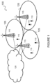
- FIGURE 1 is a block diagram illustrating an embodiment of an example wireless network 100 for sharing frequency resources between grant-free and grant-based UL transmissions, in accordance with certain embodiments.
- UL transmission without grant or “grant-free” are both used herein to refer to either of the type 1 or type 2 schemes explained above.
- configured grant or “semi-persistent scheduling” are used to describe the same or similar concepts where the described techniques may be applied.
- Network 100 includes one or more wireless devices 110A-C, which may be interchangeably referred to as wireless devices 110 or UEs 110, and network nodes 115A-C, which may be interchangeably referred to as network nodes 115 or eNodeBs 115.
- a wireless device 110 may communicate with network nodes 115 over a wireless interface.
- wireless device 110A may transmit wireless signals to one or more of network nodes 115, and/or receive wireless signals from one or more of network nodes 115.
- the wireless signals may contain voice traffic, data traffic, control signals, and/or any other suitable information.
- an area of wireless signal coverage associated with a network node 115 may be referred to as a cell.
- wireless devices 110 may have D2D capability.
- wireless devices 110 may be able to receive signals from and/or transmit signals directly to another wireless device 110.
- wireless device 110A may be able to receive signals from and/or transmit signals to wireless device 110B.
- network nodes 115 may interface with a radio network controller (not depicted in FIGURE 1 ).
- the radio network controller may control network nodes 115 and may provide certain radio resource management functions, mobility management functions, and/or other suitable functions.
- the functions of the radio network controller may be included in network node 115.
- the radio network controller may interface with a core network node.
- the radio network controller may interface with the core network node via an interconnecting network.
- the interconnecting network may refer to any interconnecting system capable of transmitting audio, video, signals, data, messages, or any combination of the preceding.
- the interconnecting network may include all or a portion of a public switched telephone network (PSTN), a public or private data network, a local area network (LAN), a metropolitan area network (MAN), a wide area network (WAN), a local, regional, or global communication or computer network such as the Internet, a wireline or wireless network, an enterprise intranet, or any other suitable communication link, including combinations thereof.
- PSTN public switched telephone network
- LAN local area network
- MAN metropolitan area network
- WAN wide area network
- Internet a local, regional, or global communication or computer network
- wireline or wireless network such as the Internet
- enterprise intranet an enterprise intranet, or any other suitable communication link, including combinations thereof.
- the core network node may manage the establishment of communication sessions and various other functionalities for wireless devices 110.
- Wireless devices 110 may exchange certain signals with the core network node using the non-access stratum layer.
- signals between wireless devices 110 and the core network node may be transparently passed through the radio access network.
- network nodes 115 may interface with one or more network nodes over an internode interface. For example, network nodes 115A and 115B may interface over an X2 interface.
- example embodiments of network 100 may include one or more wireless devices 110, and one or more different types of network nodes capable of communicating (directly or indirectly) with wireless devices 110.
- Wireless device 110 may refer to any type of wireless device communicating with a node and/or with another wireless device in a cellular or mobile communication system. Examples of wireless device 110 include a mobile phone, a smart phone, a PDA (Personal Digital Assistant), a portable computer (e.g., laptop, tablet), a sensor, a modem, a machine-type-communication (MTC) device / machine-to-machine (M2M) device, laptop embedded equipment (LEE), laptop mounted equipment (LME), USB dongles, a D2D capable device, or another device that can provide wireless communication.
- MTC machine-type-communication
- M2M machine-to-machine
- LME laptop mounted equipment
- USB dongles a D2D capable device, or another device that can provide wireless communication.
- a wireless device 110 may also be referred to as UE, a station (STA), a device, or a terminal in some embodiments.
- radio network node (or simply “network node”) is used. It can be any kind of network node, which may comprise a Node B, base station (BS), multi-standard radio (MSR) radio node such as MSR BS, eNode B, network controller, radio network controller (RNC), base station controller (BSC), relay donor node controlling relay, base transceiver station (BTS), access point (AP), transmission points, transmission nodes, RRU, RRH, nodes in distributed antenna system (DAS), core network node (e.g.
- Example embodiments of wireless devices 110, network nodes 115, and other network nodes are described in more detail with respect to FIGURES 2 , 3 , and 8 , respectively.
- FIGURE 1 illustrates a particular arrangement of network 100
- network 100 may include any suitable number of wireless devices 110 and network nodes 115, as well as any additional elements suitable to support communication between wireless devices or between a wireless device and another communication device (such as a landline telephone).
- LTE long term evolution
- the embodiments may be implemented in any appropriate type of telecommunication system supporting any suitable communication standards and using any suitable components, and are applicable to any radio access technology (RAT) or multi-RAT systems in which the wireless device receives and/or transmits signals (e.g., data).
- RAT radio access technology
- multi-RAT multi-RAT
- the various embodiments described herein may be applicable to LTE, LTE-Advanced, LTE-U UMTS, HSPA, GSM, cdma2000, WiMax, WiFi, another suitable radio access technology, or any suitable combination of one or more radio access technologies.
- LTE Long Term Evolution
- LTE-A UMTS Long Term Evolution
- GSM Global System for Mobile communications
- cdma2000 Fifth Generation
- WiMax Wireless Fidelity
- WiFi Wireless Fidelity
- the techniques for sharing and differentiating grant-free and grant-based UL transmissions described herein are applicable to both LAA LTE and standalone LTE operation in license-exempt channels.
- the described techniques are generally applicable for transmissions from both network nodes 115 and wireless devices 110.
- FIGURE 2 is a block schematic of an exemplary wireless device 110 for sharing frequency resources between grant-free and grant-based UL transmissions, in accordance with certain embodiments.
- Wireless device 110 may refer to any type of wireless device communicating with a node and/or with another wireless device in a cellular or mobile communication system. Examples of wireless device 110 include a mobile phone, a smart phone, a PDA (Personal Digital Assistant), a portable computer (e.g., laptop, tablet), a sensor, a modem, an MTC device / machine-to-machine (M2M) device, laptop embedded equipment (LEE), laptop mounted equipment (LME), USB dongles, a D2D capable device, or another device that can provide wireless communication.
- M2M machine-to-machine
- LME laptop mounted equipment
- USB dongles a D2D capable device, or another device that can provide wireless communication.
- a wireless device 110 may also be referred to as UE, a station (STA), a device, or a terminal in some embodiments.
- Wireless device 110 includes transceiver 210, processing circuitry 220, and memory 230.
- transceiver 210 facilitates transmitting wireless signals to and receiving wireless signals from network node 115 (e.g., via antenna 240), processing circuitry 220 (e.g., which may include one or more processors) executes instructions to provide some or all of the functionality described above as being provided by wireless device 110, and memory 230 stores the instructions executed by processing circuitry 220.
- Processing circuitry 220 may include any suitable combination of hardware and software implemented in one or more modules to execute instructions and manipulate data to perform some or all of the described functions of wireless device 110, such as the functions of UE 110 (i.e., wireless device 110) described herein.
- processing circuitry 220 may include, for example, one or more computers, one or more central processing units (CPUs), one or more microprocessors, one or more applications, one or more application specific integrated circuits (ASICs), one or more field programmable gate arrays (FPGAs) and/or other logic.
- CPUs central processing units
- microprocessors one or more applications
- ASICs application specific integrated circuits
- FPGAs field programmable gate arrays
- Memory 230 is generally operable to store instructions, such as a computer program, software, an application including one or more of logic, rules, algorithms, code, tables, etc. and/or other instructions capable of being executed by a processor.
- Examples of memory 230 include computer memory (for example, Random Access Memory (RAM) or Read Only Memory (ROM)), mass storage media (for example, a hard disk), removable storage media (for example, a Compact Disk (CD) or a Digital Video Disk (DVD)), and/or or any other volatile or non-volatile, non-transitory computer-readable and/or computer-executable memory devices that store information, data, and/or instructions that may be used by processor 220.
- RAM Random Access Memory
- ROM Read Only Memory
- mass storage media for example, a hard disk
- removable storage media for example, a Compact Disk (CD) or a Digital Video Disk (DVD)
- CD Compact Disk
- DVD Digital Video Disk
- wireless device 110 may optionally include additional components beyond those shown in FIGURE 2 that may be responsible for providing certain aspects of the wireless device's functionality, including any of the functionality described above and/or any additional functionality (including any functionality necessary to support the solution described above).
- wireless device 110 may include input devices and circuits, output devices, and one or more synchronization units or circuits, which may be part of the processing circuitry 220.
- Input devices include mechanisms for entry of data into wireless device 110.
- input devices may include input mechanisms, such as a microphone, input elements, a display, etc.
- Output devices may include mechanisms for outputting data in audio, video, and/or hard copy format.
- output devices may include a speaker, a display, etc.
- FIGURE 3 illustrates an example network node 115 for differentiating grant-free and grant-based UL transmissions that share one or more frequency resources, in accordance with certain embodiments.
- Network node 115 may be any type of radio network node or any network node that communicates with a UE and/or with another network node.
- network node 115 examples include an gNB, eNodeB, a node B, a base station, a wireless access point (e.g., a Wi-Fi access point), a low power node, a base transceiver station (BTS), relay, donor node controlling relay, transmission points, transmission nodes, remote RF unit (RRU), remote radio head (RRH), multi-standard radio (MSR) radio node such as MSR BS, nodes in distributed antenna system (DAS), O&M, OSS, SON, positioning node (e.g., E-SMLC), MDT, or any other suitable network node.
- Network nodes 115 may be deployed throughout network 100 as a homogenous deployment, heterogeneous deployment, or mixed deployment.
- a homogeneous deployment may generally describe a deployment made up of the same (or similar) type of network nodes 115 and/or similar coverage and cell sizes and inter-site distances.
- a heterogeneous deployment may generally describe deployments using a variety of types of network nodes 115 having different cell sizes, transmit powers, capacities, and inter-site distances.
- a heterogeneous deployment may include a plurality of low-power nodes placed throughout a macro-cell layout.
- Mixed deployments may include a mix of homogenous portions and heterogeneous portions.
- Network node 115 may include one or more of transceiver 310, processing circuitry 320 (e.g., which may include one or more processors), memory 330, and network interface 340.
- transceiver 310 facilitates transmitting wireless signals to and receiving wireless signals from wireless device 110 (e.g., via antenna 350)
- processing circuitry 320 executes instructions to provide some or all of the functionality described above as being provided by a network node 115
- memory 330 stores the instructions executed by processing circuitry 320
- network interface 340 communicates signals to backend network components, such as a gateway, switch, router, Internet, Public Switched Telephone Network (PSTN), core network nodes or radio network controllers, etc.
- PSTN Public Switched Telephone Network
- Processing circuitry 320 may include any suitable combination of hardware and software implemented in one or more modules to execute instructions and manipulate data to perform some or all of the described functions of network node 115, such as those described herein.
- processing circuitry 320 may include, for example, one or more computers, one or more central processing units (CPUs), one or more microprocessors, one or more applications, and/or other logic.
- Memory 330 is generally operable to store instructions, such as a computer program, software, an application including one or more of logic, rules, algorithms, code, tables, etc. and/or other instructions capable of being executed by a processor.
- Examples of memory 330 include computer memory (for example, Random Access Memory (RAM) or Read Only Memory (ROM)), mass storage media (for example, a hard disk), removable storage media (for example, a Compact Disk (CD) or a Digital Video Disk (DVD)), and/or or any other volatile or non-volatile, non-transitory computer-readable and/or computer-executable memory devices that store information.
- RAM Random Access Memory
- ROM Read Only Memory
- mass storage media for example, a hard disk
- removable storage media for example, a Compact Disk (CD) or a Digital Video Disk (DVD)
- CD Compact Disk
- DVD Digital Video Disk
- network interface 340 is communicatively coupled to processing circuitry 320 and may refer to any suitable device operable to receive input for network node 115, send output from network node 115, perform suitable processing of the input or output or both, communicate to other devices, or any combination of the preceding.
- Network interface 340 may include appropriate hardware (e.g., port, modem, network interface card, etc.) and software, including protocol conversion and data processing capabilities, to communicate through a network.
- network node 115 may include additional components beyond those shown in FIGURE 3 that may be responsible for providing certain aspects of the radio network node's functionality, including any of the functionality described above and/or any additional functionality (including any functionality necessary to support the solutions described above).
- the various different types of network nodes may include components having the same physical hardware but configured (e.g., via programming) to support different radio access technologies, or may represent partly or entirely different physical components.
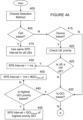
- FIGURES 4A-4B illustrates an example method by a network node 115 for selecting a SPS interval for a grant-free type of transmission from a wireless device, according to certain embodiments.
- the method begins at step 400 when network node 115 chooses a method for selecting the SPS interval.
- the methods for selecting the SPS interval may include any one or more of: a cell-based selection method, a device-based selection method, a QCI-based selection method, and a load-based selection method.
- step 405 it is determined whether a cell-based selection method was selected at step 400. If a cell-based selection method was selected, network node 115 uses the same SPS interval for all wireless devices 110 in a cell 125. In a particular embodiment, if the number of wireless devices in a cell 125 is less than a threshold, network node 115 may decided to use cell-based selection and assign the same short SPS interval to all wireless devices 110. in a particular embodiment, the short SPS interval may be on the order of 1 ms.
- network node 115 may determine, at step 415, whether a device-based selection method was selected at step 400. If a device-based selection method was selected, network node 115 may check a priority of a wireless device 110, at step 420. In a particular embodiment, for example, network node 115 may determining the priority of the wireless device based on a subscriber profile identifier associated with a user of the wireless device.
- a determination may be made as to whether the wireless device 110 is considered a VIP wireless device, If the wireless device 110 is a VIP wireless device, network node 115 may select a shorter SPS interval than if the wireless device 110 were a non-VIP wireless device. In a particular embodiment, for example, network node 115 may schedule a VIP wireless device 110 with a short SPS interval of approximately 1 ms. Conversely, if the wireless device 110 is not a VIP wireless device, network node 115 may assign a SPS interval that is longer than 1 ms and/or continue to step 435 to determine if a QCI-based selection method was selected at step 400.
- a plurality of QCIs may be associated with the wireless device. Each of the QCIs may be associated with a particular SPS interval. In this scenario, network node 115 may assign the SPS interval by selecting a SPS interval from the plurality of SPS intervals that corresponds to a particular one of the plurality of QCIs with a highest priority.
- Network node 115 may then monitor system resources, at step 460.
- the system resources may be monitored during a measurement window to determine a measure of available resources in the cell.
- Network node 115 may then assign the SPS interval to the wireless device based on the measure of available resources in the cell.
- network node 115 may determining an actual amount of resources utilized by all wireless devices scheduled in the cell during a transmission time interval. The actual amount of resources utilized by all wireless devices scheduled in the cell during the transmission time interval may be filtered over the measurement window, where the measurement window comprises one or more transmission time intervals. In a particular embodiment, network node 115 may determine the measure of the available resources in the cell based on a difference between a total amount of resources utilized during the one or more transmission time intervals of the measurement window and an amount of resources filtered over the measurement window.
- the utilized resources may be compared to at least one threshold. For example, in a particular embodiment, a measure of the actual amount of resources utilized by all wireless devices scheduled in the cell during the transmission time interval as filtered over the measurement window may be compared to a threshold. If the measure of the actual amount of resources utilized by all wireless devices scheduled in the cell during the transmission time interval as filtered over the measurement window is less than a threshold, selecting a first SPS interval. Conversely, if the measure of the actual amount of resources utilized by all wireless devices scheduled in the cell during the transmission time interval as filtered over the measurement window is not less than the threshold, selecting a second SPS interval.
- the utilized resources may be compared to multiple thresholds at steps 465-485 and the SPS interval may be selected based on the appropriate threshold. For example, at step 465, the actual amount of utilized resources may be compared to a first threshold, which may be a very low threshold. If it is determined at step 465, that the utilized resources are less than the very low threshold, network node 115 may select a first SPS interval at step 470.
- a first threshold which may be a very low threshold.
- step 475 network node 115 may compare the utilized resources to a second threshold, which may be a low threshold. If it is determined at step 475 that the utilized resources are less than the second threshold, a second SPS interval may be selected at step 480.
- step 485 network node 115 may compare the utilized resources to a third threshold, which may be a medium threshold, in a particular embodiment. If the utilized resources are less than the third threshold, a third SPS interval may be selected at step 490.
- step 492 network node 115 may determine if the utilized resources are less than or equal to a fourth threshold, which may be a high threshold. If network node 115 determines that the utilized resources are less than the fourth threshold, network node 115 may select a fourth interval at step 494. Conversely, if network node 115 determines that the utilized resources are greater than or equal to the fourth threshold, network node 115 may select a fifth interval at step 496.
- a fourth threshold which may be a high threshold. If network node 115 determines that the utilized resources are less than the fourth threshold, network node 115 may select a fourth interval at step 494. Conversely, if network node 115 determines that the utilized resources are greater than or equal to the fourth threshold, network node 115 may select a fifth interval at step 496.
- FIGURE 4 depicts the various selection methods being performed in the alternative (i.e., device-based selection is performed only if cell-based selection is not), it is recognized that network node 115 may select the SPS interval using any combination of cell-based selection, device-based selection, QCI-based selection, and/or load-based selection. For example, network node 115 may perform steps 420-430, which are associated with the device-based selection method, and steps 440, which is associated with the QCI-based selection method, and assign the SPS interval based on both selection methods.
- a network node 115 may assign weights to the different selection methods being used. For example, a network node 115 may perform both UE-based selection and load-based selection but give more weight to the UE-based selection. Another network node 115 may give more weight to the load-based selection.
- the SPS interval may be dynamically assigned.
- network node 115 may perform some or all of the steps illustrated in FIGURE 4 to determine a SPS interval. However, if traffic in the cell 125 changes or the load at network node 115 changes, network node 115 may assign a new SPS interval based on the changes.
- FIGURE 5 illustrates an example distribution of frequency-time resources when different SPS intervals are assigned to different wireless devices in a cell, according to certain embodiments.
- network node 115 assigns resources to three UEs. At a first and third time intervals, resources are divided between UE1 and UE2. However, at second and fourth time intervals, resources are divided between UE1 and UE3. Thus, UE 1 is assigned a short 1 ms SPS interval, and both of UE2 and UE3 are assigned a short 2 ms SPS interval. By supporting different SPS intervals for different UEs, resources can be time shared by more UEs in the system.
- FIGURE 6 illustrates another example method by a network node for selecting a SPS interval for a grant-free type of transmission from a wireless device 110, according to certain embodiments.
- the method begins at step 610 when network node 115 determines criterion for selecting the SPS interval for the wireless device 110.
- the criterion being associated with at least one of a QoS requirement of the wireless device and a utilization of resources by the network node.
- the criterion is associated with a priority of the wireless device, and network node 115 may assign the SPS interval based on the priority of the wireless device.
- network node 115 assigns the SPS interval to the wireless device based on the criterion
- the method may further include determining whether wireless device 110 is a VIP wireless device.
- the priority of wireless device 110 may be determined based on a subscriber profile identifier associated with a user of wireless device 110.
- network node 115 may assign a shorter SPS interval.
- the shorter SPS interval may be on the order of 1 ms.
- the criterion may be associated with a QCI, and network node 115 may further operate to determine at least one QCI associated with wireless device 110. Network node may then assign the SPS interval to wireless device 110 based on the at least one QCI associated with wireless device 1 10.
- wireless device 110 may be associated with a plurality of QCIs, and each QCI may be associated with a respective one of a plurality of SPS intervals.
- Network node 115 may select a SPS interval that corresponds to a particular one of the plurality of QCIs with a highest priority when assigning the SPS interval.
- the criterion may be associated with the utilization of resources by the network node, and network node 115 may operate to monitor system resources during a measurement window to determine a measure of available resources in the cell 125. Network node 115 may assign the SPS interval based on the measure of available resources in the cell.
- network node 115 may determine an actual amount of resources utilized by all wireless devices 110 scheduled in the cell 125 during a transmission time interval.
- Network node 115 may filter the actual amount of resources utilized by all wireless devices 110 scheduled in the cell 125 during the transmission time interval over the measurement window.
- the measurement window may include one or more transmission time intervals.
- network node 115 may determine the measure of available resources in cell 125 based on a difference between the average available during measurement period and the filtered amount of resources utilized during the measurement window.
- network node 115 may compare a measure of the actual amount of resources utilized by all wireless devices 110 scheduled in cell 125 as filtered over the measurement window to a threshold. If the measure of the actual amount of resources utilized by all wireless devices 110 scheduled in the cell 125 during the transmission time interval as filtered over the measurement window is less than a threshold, network node 115 may select a first SPS interval. Conversely, if the measure of the actual amount of resources utilized by all wireless devices 110 scheduled in the cell 125 during the transmission time interval as filtered over the measurement window is not less than the threshold, network node 115 may select a second SPS interval.
- network node 115 may compare the measure of the available resources in cell 125 to a plurality of thresholds that are each associated with a selected one of a plurality of SPS intervals. For example, a shorter SPS interval may be associated with a highest threshold and a longer SPS interval may be associated with a lowest threshold.
- network node 115 may determine that the QoS requirements of wireless device 110 or the utilization of resources by network node 115 has changed since the assignment of the SPS interval. Network node 115 may then adjust the SPS interval for wireless device 110 in response to determining that the at least one of the QoS requirement of wireless device 110 or the utilization of resources by network node 115 has changed.
- FIGURE 7 illustrates an example virtual computing device for selecting a SPS interval for a grant-free type of transmission from a wireless device, according to certain embodiments.
- virtual computing device 600 may include modules for performing steps similar to those described above with regard to the method illustrated and described in FIGURE 6 .
- virtual computing device 700 may include a determining module 710, an assigning module 720, and any other suitable modules for selecting a SPS interval for a grant-free type of transmission from a wireless device 110.
- one or more of the modules may be implemented using processing circuitry 320 of FIGURE 3 .
- the functions of two or more of the various modules may be combined into a single module.
- the determining module 710 may perform certain of the determining functions of virtual computing device 700. For example, in a particular embodiment, determining module 710 may determine criterion for selecting the SPS interval for the wireless device 110.
- the assigning module 720 may perform certain of the assigning functions of virtual computing device 700. For example, in a particular embodiment, assigning module 720 may assign the SPS interval to the wireless device 110 based on the criterion.
- virtual computing device 700 may include additional components beyond those shown in FIGURE 7 that may be responsible for providing certain aspects of the network node's functionality, including any of the functionality described above and/or any additional functionality (including any functionality necessary to support the solutions described above).
- the various different types of wireless devices may include components having the same physical hardware but configured (e.g., via programming) to support different radio access technologies, or may represent partly or entirely different physical components.
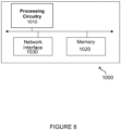
- FIGURE 8 illustrates an example radio network controller or core network node 800, in accordance with certain embodiments.
- network nodes can include a mobile switching center (MSC), a serving GPRS support node (SGSN), a mobility management entity (MME), a radio network controller (RNC), a base station controller (BSC), and so on.
- the radio network controller or core network node includes processing circuitry 810 (e.g., which may include one or more processors), network interface 820, and memory 830.
- processing circuitry 810 executes instructions to provide some or all of the functionality described above as being provided by the network node
- memory 830 stores the instructions executed by processing circuitry 810
- network interface 820 communicates signals to any suitable node, such as a gateway, switch, router, Internet, Public Switched Telephone Network (PSTN), network nodes 115, radio network controllers or core network nodes, etc.
- PSTN Public Switched Telephone Network
- Processing circuitry 810 may include any suitable combination of hardware and software implemented in one or more modules to execute instructions and manipulate data to perform some or all of the described functions of the radio network controller or core network node.
- processing circuitry 810 may include, for example, one or more computers, one or more central processing units (CPUs), one or more microprocessors, one or more applications, and/or other logic.
- CPUs central processing units
- microprocessors one or more applications, and/or other logic.
- Memory 830 is generally operable to store instructions, such as a computer program, software, an application including one or more of logic, rules, algorithms, code, tables, etc. and/or other instructions capable of being executed by a processor.
- Examples of memory 830 include computer memory (for example, Random Access Memory (RAM) or Read Only Memory (ROM)), mass storage media (for example, a hard disk), removable storage media (for example, a Compact Disk (CD) or a Digital Video Disk (DVD)), and/or or any other volatile or non-volatile, non-transitory computer-readable and/or computer-executable memory devices that store information.
- RAM Random Access Memory
- ROM Read Only Memory
- mass storage media for example, a hard disk
- removable storage media for example, a Compact Disk (CD) or a Digital Video Disk (DVD)
- CD Compact Disk
- DVD Digital Video Disk
- network interface 820 is communicatively coupled to processing circuitry 810 and may refer to any suitable device operable to receive input for the network node, send output from the network node, perform suitable processing of the input or output or both, communicate to other devices, or any combination of the preceding.
- Network interface 820 may include appropriate hardware (e.g., port, modem, network interface card, etc.) and software, including protocol conversion and data processing capabilities, to communicate through a network.
- network node may include additional components beyond those shown in FIGURE 8 that may be responsible for providing certain aspects of the network node's functionality, including any of the functionality described above and/or any additional functionality (including any functionality necessary to support the solution described above).
- FIGURE 9 schematically illustrates a telecommunication network connected via an intermediate network to a host computer, according to certain embodiments.
- a communication system includes a telecommunication network 3210, such as a 3GPP-type cellular network, which comprises an access network 3211, such as a radio access network, and a core network 3214.
- the access network 3211 comprises a plurality of base stations 3212a, 3212b, 3212c, such as NBs, eNBs, gNBs or other types of wireless access points, each defining a corresponding coverage area 3213a, 3213b, 3213c.
- Each base station 3212a, 3212b, 3212c is connectable to the core network 3214 over a wired or wireless connection 3215.
- a first user equipment (UE) 3291 located in coverage area 3213c is configured to wirelessly connect to, or be paged by, the corresponding base station 3212c.
- a second UE 3292 in coverage area 3213a is wirelessly connectable to the corresponding base station 3212a. While a plurality of UEs 3291, 3292 are illustrated in this example, the disclosed embodiments are equally applicable to a situation where a sole UE is in the coverage area or where a sole UE is connecting to the corresponding base station 3212.
- the telecommunication network 3210 is itself connected to a host computer 3230, which may be embodied in the hardware and/or software of a standalone server, a cloud-implemented server, a distributed server or as processing resources in a server farm.
- the host computer 3230 may be under the ownership or control of a service provider, or may be operated by the service provider or on behalf of the service provider.
- the connections 3221, 3222 between the telecommunication network 3210 and the host computer 3230 may extend directly from the core network 3214 to the host computer 3230 or may go via an optional intermediate network 3220.
- the intermediate network 3220 may be one of, or a combination of more than one of, a public, private or hosted network; the intermediate network 3220, if any, may be a backbone network or the Internet; in particular, the intermediate network 3220 may comprise two or more sub-networks (not shown).
- the communication system of FIGURE 9 as a whole enables connectivity between one of the connected UEs 3291, 3292 and the host computer 3230.
- the connectivity may be described as an over-the-top (OTT) connection 3250.
- the host computer 3230 and the connected UEs 3291, 3292 are configured to communicate data and/or signaling via the OTT connection 3250, using the access network 3211, the core network 3214, any intermediate network 3220 and possible further infrastructure (not shown) as intermediaries.
- the OTT connection 3250 may be transparent in the sense that the participating communication devices through which the OTT connection 3250 passes are unaware of routing of uplink and downlink communications.
- a base station 3212 may not or need not be informed about the past routing of an incoming downlink communication with data originating from a host computer 3230 to be forwarded (e.g., handed over) to a connected UE 3291. Similarly, the base station 3212 need not be aware of the future routing of an outgoing uplink communication originating from the UE 3291 towards the host computer 3230.
- FIGURE 10 is a generalized block diagram of a host computer communicating via a base station with a user equipment over a partially wireless connection, according to certain embodiments.
- Example implementations, in accordance with an embodiment, of the UE, base station and host computer discussed in the preceding paragraphs will now be described with reference to FIGURE 9 .
- a host computer 3110 comprises hardware 3115 including a communication interface 3316 configured to set up and maintain a wired or wireless connection with an interface of a different communication device of the communication system 1100.
- the host computer 3110 further comprises processing circuitry 3318, which may have storage and/or processing capabilities.
- the processing circuitry 3318 may comprise one or more programmable processors, application-specific integrated circuits, field programmable gate arrays or combinations of these (not shown) adapted to execute instructions.
- the host computer 3110 further comprises software 3311, which is stored in or accessible by the host computer 3110 and executable by the processing circuitry 3318.
- the software 3311 includes a host application 3312.
- the host application 3312 may be operable to provide a service to a remote user, such as a UE 3330 connecting via an OTT connection 3350 terminating at the UE 3330 and the host computer 3110. In providing the service to the remote user, the host application 3312 may provide user data which is transmitted using the OTT connection 3350.
- the communication system 1100 further includes a base station 3320 provided in a telecommunication system and comprising hardware 3325 enabling it to communicate with the host computer 3110 and with the UE 3330.
- the hardware 3325 may include a communication interface 3326 for setting up and maintaining a wired or wireless connection with an interface of a different communication device of the communication system 1100, as well as a radio interface 3327 for setting up and maintaining at least a wireless connection 3370 with a UE 3330 located in a coverage area (not shown in FIGURE 10 ) served by the base station 3320.
- the communication interface 3326 may be configured to facilitate a connection 3360 to the host computer 3110.
- connection 3360 may be direct or it may pass through a core network (not shown in FIGURE 10 ) of the telecommunication system and/or through one or more intermediate networks outside the telecommunication system.
- the hardware 3325 of the base station 3320 further includes processing circuitry 3328, which may comprise one or more programmable processors, application-specific integrated circuits, field programmable gate arrays or combinations of these (not shown) adapted to execute instructions.
- the base station 3320 further has software 3321 stored internally or accessible via an external connection.
- the communication system 1100 further includes the UE 3330 already referred to.
- Its hardware 3335 may include a radio interface 3337 configured to set up and maintain a wireless connection 3370 with a base station serving a coverage area in which the UE 3330 is currently located.
- the hardware 3335 of the UE 3330 further includes processing circuitry 3338, which may comprise one or more programmable processors, application-specific integrated circuits, field programmable gate arrays or combinations of these (not shown) adapted to execute instructions.
- the UE 3330 further comprises software 3331, which is stored in or accessible by the UE 3330 and executable by the processing circuitry 3338.
- the software 3331 includes a client application 3332.
- the client application 3332 may be operable to provide a service to a human or non-human user via the UE 3330, with the support of the host computer 3110.
- an executing host application 3312 may communicate with the executing client application 3332 via the OTT connection 3350 terminating at the UE 3330 and the host computer 3110.
- the client application 3332 may receive request data from the host application 3312 and provide user data in response to the request data.
- the OTT connection 3350 may transfer both the request data and the user data.
- the client application 3332 may interact with the user to generate the user data that it provides.
- the host computer 3110, base station 3320 and UE 3330 illustrated in FIGURE 10 maybe identical to the host computer 3230, one of the base stations 3212a, 3212b, 3212c and one of the UEs 3291, 3292 of FIGURE 9 , respectively.
- the inner workings of these entities may be as shown in FIGURE 10 and independently, the surrounding network topology may be that of FIGURE 9 .
- the OTT connection 3350 has been drawn abstractly to illustrate the communication between the host computer 3110 and the use equipment 3330 via the base station 3320, without explicit reference to any intermediary devices and the precise routing of messages via these devices.
- Network infrastructure may determine the routing, which it may be configured to hide from the UE 3330 or from the service provider operating the host computer 3110, or both. While the OTT connection 3350 is active, the network infrastructure may further take decisions by which it dynamically changes the routing (e.g., on the basis of load balancing consideration or reconfiguration of the network).
- the wireless connection 3370 between the UE 3330 and the base station 3320 is in accordance with the teachings of the embodiments described throughout this disclosure.
- One or more of the various embodiments improve the performance of OTT services provided to the UE 3330 using the OTT connection 3350, in which the wireless connection 3370 forms the last segment. More precisely, the teachings of these embodiments may improve the data rate and/or latency and thereby provide benefits such as reduced user waiting time, relaxed restriction on file size, and better responsiveness.
- a measurement procedure may be provided for the purpose of monitoring data rate, latency and other factors on which the one or more embodiments improve.
- the measurement procedure and/or the network functionality for reconfiguring the OTT connection 3350 may be implemented in the software 3311 of the host computer 3110 or in the software 3331 of the UE 3330, or both.
- sensors (not shown) may be deployed in or in association with communication devices through which the OTT connection 3350 passes; the sensors may participate in the measurement procedure by supplying values of the monitored quantities exemplified above, or supplying values of other physical quantities from which software 3311, 3331 may compute or estimate the monitored quantities.
- the reconfiguring of the OTT connection 3350 may include message format, retransmission settings, preferred routing etc.; the reconfiguring need not affect the base station 3320, and it may be unknown or imperceptible to the base station 3320. Such procedures and functionalities may be known and practiced in the art.
- measurements may involve proprietary UE signaling facilitating the host computer's 3110 measurements of throughput, propagation times, latency and the like.
- the measurements may be implemented in that the software 3311, 3331 causes messages to be transmitted, in particular empty or 'dummy' messages, using the OTT connection 3350 while it monitors propagation times, errors etc.
- FIGURE 11 is a flowchart illustrating a method implemented in a communication system, in accordance with one embodiment.
- the communication system includes a host computer, a base station and a UE which may be those described with reference to FIGURES 9 and 10 .
- the host computer provides user data.
- the host computer provides the user data by executing a host application.
- the host computer initiates a transmission carrying the user data to the UE.
- the base station transmits to the UE the user data which was carried in the transmission that the host computer initiated, in accordance with the teachings of the embodiments described throughout this disclosure.
- the UE executes a client application associated with the host application executed by the host computer.
- FIGURE 12 is a flowchart illustrating a method implemented in a communication system, in accordance with one embodiment.
- the communication system includes a host computer, a base station and a UE which may be those described with reference to FIGURES 9 and 10 .
- the host computer provides user data.
- the host computer provides the user data by executing a host application.
- the host computer initiates a transmission carrying the user data to the UE. The transmission may pass via the base station, in accordance with the teachings of the embodiments described throughout this disclosure.
- the UE receives the user data carried in the transmission.
Landscapes
- Engineering & Computer Science (AREA)
- Computer Networks & Wireless Communication (AREA)
- Signal Processing (AREA)
- Quality & Reliability (AREA)
- Mobile Radio Communication Systems (AREA)
Claims (13)
- Procédé par un noeud de réseau (115) pour sélectionner un intervalle d'ordonnancement semi-persistant, SPS, pour un dispositif sans fil (110) dans une cellule (125) desservie par le noeud de réseau, le procédé comprenant :la détermination (610) d'un critère pour sélectionner l'intervalle SPS pour le dispositif sans fil (110), le critère étant associé à :
une utilisation de ressources par le noeud de réseau ; etl'attribution (620) de l'intervalle SPS au dispositif sans fil sur la base du critère,dans lequel le critère est associé à l'utilisation de ressources par le noeud de réseau, et le procédé comprend en outre la surveillance de ressources de système dans une fenêtre de mesure pour déterminer une mesure de ressources disponibles dans la cellule, et dans lequel l'attribution de l'intervalle SPS au dispositif sans fil comprend l'attribution de l'intervalle SPS sur la base de la mesure de ressources disponibles dans la cellule,dans lequel la surveillance de ressources de système comprend :la détermination d'une quantité réelle de ressources utilisées par tous les dispositifs sans fil ordonnancés dans la cellule au cours d'un intervalle de temps de transmission ; etle filtrage de la quantité réelle de ressources utilisées par tous les dispositifs sans fil ordonnancés dans la cellule au cours de l'intervalle de temps de transmission dans la fenêtre de mesure, dans lequel la fenêtre de mesure comprend un ou plusieurs intervalles de temps de transmission. - Procédé selon la revendication 1, dans lequel :le critère est associé à une pluralité du dispositif sans fil, etl'intervalle SPS est attribué sur la base de la priorité du dispositif sans fil.
- Procédé selon la revendication 2, comprenant en outre la détermination si le dispositif sans fil est ou non un dispositif sans fil VIP, et dans lequel l'attribution de l'intervalle SPS comprend :l'attribution d'un intervalle SPS plus court si le dispositif sans fil est un dispositif sans fil VIP ; etl'attribution d'un intervalle SPS plus long si le dispositif sans fil n'est pas un dispositif sans fil VIP.
- Procédé selon la revendication 3, dans lequel l'intervalle SPS plus court est pour un intervalle de temps de 1 ms.
- Procédé selon l'une quelconque des revendications 2 à 4, comprenant en outre la détermination de la priorité du dispositif sans fil sur la base d'un identifiant de profil d'abonné associé à un utilisateur du dispositif sans fil.
- Procédé selon l'une quelconque des revendications 1 à 5, dans lequel le critère est associé à un identifiant de classe de qualité de service, QCI, et le procédé comprend en outre la détermination d'au moins un QCI associé au dispositif sans fil, et dans lequel l'attribution de l'intervalle SPS au dispositif sans fil comprend l'attribution de l'intervalle SPS sur la base de l'au moins un QCI associé au dispositif sans fil.
- Procédé selon la revendication 6, dans lequel :une pluralité de QCI sont associés au dispositif sans fil,chacun de la pluralité de QCI sont associés à l'un respectif d'une pluralité d'intervalles SPS, etl'attribution de l'intervalle SPS comprend la sélection d'un intervalle SPS parmi la pluralité d'intervalles SPS qui correspond à l'un particulier parmi la pluralité de QCI avec une priorité la plus grande.
- Procédé selon la revendication 1, comprenant en outre :la comparaison d'une mesure de la quantité réelle de ressources utilisées par tous les dispositifs sans fil ordonnancés dans la cellule au cours de l'intervalle de temps de transmission tels que filtrés dans la fenêtre de mesure à un seuil ;si la mesure de la quantité réelle de ressources utilisées par tous les dispositifs sans fil ordonnancés dans la cellule au cours de l'intervalle de temps de transmission tels que filtrés dans la fenêtre de mesure est inférieure à un seuil, la sélection d'un premier intervalle SPS ; etsi la mesure de la quantité réelle de ressources utilisées par tous les dispositifs sans fil ordonnancés dans la cellule au cours de l'intervalle de temps de transmission tels que filtrés dans la fenêtre de mesure n'est pas inférieure au seuil, la sélection d'un deuxième intervalle SPS.
- Procédé selon la revendication 1, comprenant en outre :
la comparaison de la mesure de ressources disponibles dans la cellule à une pluralité de seuils, chacun de la pluralité de seuils étant associé à l'un sélectionné parmi une pluralité d'intervalles SPS, et dans lequel un intervalle SPS plus court est associé à un seuil le plus haut et un intervalle SPS plus long est associé à un seuil le plus bas. - Procédé selon l'une quelconque des revendications 1 à 9, comprenant en outre :la détermination qu'une exigence de QoS du dispositif sans fil ou l'utilisation de ressources par le noeud de réseau a changé depuis l'attribution de l'intervalle SPS ; etl'ajustement de l'intervalle SPS pour le dispositif sans fil en réponse à la détermination que l'au moins une parmi l'exigence de QoS du dispositif sans fil et l'utilisation de ressources par le noeud de réseau a changé.
- Procédé mis un œuvre dans un système de communication incluant un ordinateur hôte, une station de base et un équipement utilisateur, UE, le procédé comprenant :au niveau de l'ordinateur hôte, la fourniture de données d'utilisateur ; etau niveau de l'ordinateur hôte, l'initiation d'une transmission portant les données d'utilisateur à l'UE via un réseau cellulaire comprenant la station de base, dans lequel la station de base réalisela détermination (610) d'un critère pour sélectionner l'intervalle SPS pour l'UE, le critère étant associé à :
une utilisation de ressources par la station de base ; etl'attribution (620) de l'intervalle SPS à l'UE sur la base du critère,dans lequel le critère est associé à l'utilisation de ressources par le noeud de réseau, et le procédé comprend en outre la surveillance de ressources de système dans une fenêtre de mesure pour déterminer une mesure de ressources disponibles dans la cellule, et dans lequel l'attribution de l'intervalle SPS au dispositif sans fil comprend l'attribution de l'intervalle SPS sur la base de la mesure de ressources disponibles dans la cellule,dans lequel la surveillance de ressources de système comprend :la détermination d'une quantité réelle de ressources utilisées par tous les dispositifs sans fil ordonnancés dans la cellule au cours d'un intervalle de temps de transmission ; etle filtrage de la quantité réelle de ressources utilisées par tous les dispositifs sans fil ordonnancés dans la cellule au cours de l'intervalle de temps de transmission dans la fenêtre de mesure, dans lequel la fenêtre de mesure comprend un ou plusieurs intervalles de temps de transmission. - Noeud de réseau (115) pour sélectionner un intervalle d'ordonnancement semi-persistant, SPS, pour un dispositif sans fil (110) dans une cellule (125) desservie par le noeud de réseau, le noeud de réseau comprenant :une mémoire (330) stockant des instructions ; etune circuiterie de traitement (320) configurée pour exécuter les instructions pour amener le noeud de réseau à :déterminer un critère pour sélectionner l'intervalle SPS pour le dispositif sans fil (110), le critère étant associé à :
une utilisation de ressources par le noeud de réseau ; etattribuer l'intervalle SPS au dispositif sans fil sur la base du critère,dans lequel le critère est associé à l'utilisation de ressources par le noeud de réseau ; etla circuiterie de traitement est en outre configurée pour exécuter les instructions pour amener le noeud de réseau à surveiller des ressources de système (460) dans une fenêtre de mesure pour déterminer une mesure de ressources disponibles dans la cellule ; etl'attribution de l'intervalle SPS au dispositif sans fil comprend l'attribution de l'intervalle SPS sur la base de la mesure de ressources disponibles dans la cellule,dans lequel la surveillance de ressources de système comprend :la détermination d'une quantité réelle de ressources utilisées par tous les dispositifs sans fil ordonnancés dans la cellule au cours d'un intervalle de temps de transmission ; etle filtrage de la quantité réelle de ressources utilisées par tous les dispositifs sans fil ordonnancés dans la cellule au cours de l'intervalle de temps de transmission dans la fenêtre de mesure, dans lequel la fenêtre de mesure comprend un ou plusieurs intervalles de temps de transmission. - Système de communication incluant un ordinateur hôte comprenant :une circuiterie de traitement configurée pour fournir des données d'utilisateur ; etune interface de communication configurée pour transférer les données d'utilisateur à un réseau cellulaire pour leur transmission à un équipement utilisateur, UE,dans lequel le réseau cellulaire comprend une station de base ayant une interface radio et une circuiterie de traitement, la circuiterie de traitement de la station de base étant configurée pour :déterminer un critère pour sélectionner l'intervalle SPS pour l'UE, le critère étant associé à :
une utilisation de ressources par la station de base ; etattribuer l'intervalle SPS à l'UE sur la base du critère,dans lequel le critère est associé à l'utilisation de ressources par le noeud de réseau ; etla circuiterie de traitement est en outre configurée pour exécuter les instructions pour amener le noeud de réseau à surveiller des ressources de système (460) dans une fenêtre de mesure pour déterminer une mesure de ressources disponibles dans la cellule ; etl'attribution de l'intervalle SPS au dispositif sans fil comprend l'attribution de l'intervalle SPS sur la base de la mesure de ressources disponibles dans la cellule,dans lequel la surveillance de ressources de système comprend :la détermination d'une quantité réelle de ressources utilisées par tous les dispositifs sans fil ordonnancés dans la cellule au cours d'un intervalle de temps de transmission ; etle filtrage de la quantité réelle de ressources utilisées par tous les dispositifs sans fil ordonnancés dans la cellule au cours de l'intervalle de temps de transmission dans la fenêtre de mesure, dans lequel la fenêtre de mesure comprend un ou plusieurs intervalles de temps de transmission.
Applications Claiming Priority (1)
| Application Number | Priority Date | Filing Date | Title |
|---|---|---|---|
| PCT/CN2018/080485 WO2019183754A1 (fr) | 2018-03-26 | 2018-03-26 | Sélection d'un intervalle d'ordonnancement semi-persistant pour des dispositifs sans fil sans autorisation |
Publications (3)
| Publication Number | Publication Date |
|---|---|
| EP3777415A1 EP3777415A1 (fr) | 2021-02-17 |
| EP3777415A4 EP3777415A4 (fr) | 2021-11-17 |
| EP3777415B1 true EP3777415B1 (fr) | 2024-01-10 |
Family
ID=68059421
Family Applications (1)
| Application Number | Title | Priority Date | Filing Date |
|---|---|---|---|
| EP18912361.5A Active EP3777415B1 (fr) | 2018-03-26 | 2018-03-26 | Sélection d'un intervalle d'ordonnancement semi-persistant pour des dispositifs sans fil sans autorisation |
Country Status (4)
| Country | Link |
|---|---|
| US (1) | US11425736B2 (fr) |
| EP (1) | EP3777415B1 (fr) |
| ES (1) | ES2971717T3 (fr) |
| WO (1) | WO2019183754A1 (fr) |
Families Citing this family (2)
| Publication number | Priority date | Publication date | Assignee | Title |
|---|---|---|---|---|
| CN109219148A (zh) * | 2017-06-29 | 2019-01-15 | 索尼公司 | 基于免授权频段的无线通信方法和装置 |
| US12568493B2 (en) * | 2019-03-28 | 2026-03-03 | Telefonaktiebolaget Lm Ericsson (Publ) | Multiple downlink semi-persistent scheduling configurations for New Radio Internet of Things |
Family Cites Families (9)
| Publication number | Priority date | Publication date | Assignee | Title |
|---|---|---|---|---|
| CN101742427B (zh) * | 2008-11-19 | 2013-04-24 | 华为技术有限公司 | 发送、接收和传输业务数据的方法、装置和系统 |
| CN102056174B (zh) | 2010-12-16 | 2014-03-12 | 大唐移动通信设备有限公司 | 一种资源调度的方法、装置和基站 |
| CN102131297B (zh) | 2011-03-16 | 2013-03-27 | 电信科学技术研究院 | 上行资源分配方法和设备 |
| WO2013046468A1 (fr) * | 2011-09-30 | 2013-04-04 | 富士通株式会社 | Système de communication sans fil, station mobile, station de base et procédé de commande de système de communication sans fil |
| KR101284828B1 (ko) * | 2011-12-07 | 2013-07-10 | 주식회사 케이티 | 사용자 채널 상태에 따른 반-지속 스케줄링 방법 및 그 방법을 수행하는 기지국 장치 |
| WO2016182349A1 (fr) * | 2015-05-11 | 2016-11-17 | Samsung Electronics Co., Ltd. | Procédé et système de planification de ressources en fonction du contexte |
| EP4009727B1 (fr) | 2016-03-30 | 2025-07-02 | InterDigital Patent Holdings, Inc. | Procédés et systèmes permettant une planification dans une communication entre véhicules basée sur uu |
| CN107580340B (zh) | 2016-07-05 | 2020-01-17 | 普天信息技术有限公司 | 一种v2x网络中的资源调度方法 |
| US10356758B2 (en) | 2016-08-11 | 2019-07-16 | Asustek Computer Inc. | Method and apparatus for requesting and modifying resource configuration in a wireless communication system |
-
2018
- 2018-03-26 ES ES18912361T patent/ES2971717T3/es active Active
- 2018-03-26 WO PCT/CN2018/080485 patent/WO2019183754A1/fr not_active Ceased
- 2018-03-26 EP EP18912361.5A patent/EP3777415B1/fr active Active
- 2018-03-26 US US17/041,337 patent/US11425736B2/en active Active
Also Published As
| Publication number | Publication date |
|---|---|
| WO2019183754A1 (fr) | 2019-10-03 |
| US11425736B2 (en) | 2022-08-23 |
| EP3777415A1 (fr) | 2021-02-17 |
| EP3777415A4 (fr) | 2021-11-17 |
| US20210084668A1 (en) | 2021-03-18 |
| ES2971717T3 (es) | 2024-06-06 |
Similar Documents
| Publication | Publication Date | Title |
|---|---|---|
| US11070302B2 (en) | Measurement and report for cross-link interference management based on signal strength | |
| CN109845130B (zh) | 与为在无线通信网络中工作的通信设备提供波束覆盖有关的方法和装置 | |
| US10440581B2 (en) | Inter-carrier D2D resource allocation | |
| US10098122B2 (en) | System and method for resource allocation for device-to-device communications | |
| US10237809B2 (en) | Provisioning transmission pools for inter-carrier prose direct discovery | |
| US11716739B2 (en) | Method and apparatus for uplink transmission | |
| US11387975B2 (en) | System and method for distributed coordination of duplex directions in a NR system | |
| US20210127372A1 (en) | Communication method and apparatus and communication system | |
| EP4268483A1 (fr) | Dispositif de terminal, noeud de réseau et leurs procédés de rapport de mesures | |
| US10667290B2 (en) | Method for handling users with different timing alignment requirements | |
| US20220015125A1 (en) | Method and Network Node for Coordination of Configured Scheduling | |
| US11497022B2 (en) | Grid design for introducing gaps in transmission for DL NB-IoT | |
| US11425736B2 (en) | Selecting a semi-persistent scheduling interval for grant-free wireless devices | |
| US11799625B2 (en) | Explicit measurement definition | |
| WO2022027307A1 (fr) | Procédé et appareil de commande de porteuse |
Legal Events
| Date | Code | Title | Description |
|---|---|---|---|
| STAA | Information on the status of an ep patent application or granted ep patent |
Free format text: STATUS: THE INTERNATIONAL PUBLICATION HAS BEEN MADE |
|
| PUAI | Public reference made under article 153(3) epc to a published international application that has entered the european phase |
Free format text: ORIGINAL CODE: 0009012 |
|
| STAA | Information on the status of an ep patent application or granted ep patent |
Free format text: STATUS: REQUEST FOR EXAMINATION WAS MADE |
|
| 17P | Request for examination filed |
Effective date: 20200707 |
|
| AK | Designated contracting states |
Kind code of ref document: A1 Designated state(s): AL AT BE BG CH CY CZ DE DK EE ES FI FR GB GR HR HU IE IS IT LI LT LU LV MC MK MT NL NO PL PT RO RS SE SI SK SM TR |
|
| AX | Request for extension of the european patent |
Extension state: BA ME |
|
| DAV | Request for validation of the european patent (deleted) | ||
| DAX | Request for extension of the european patent (deleted) | ||
| A4 | Supplementary search report drawn up and despatched |
Effective date: 20211020 |
|
| RIC1 | Information provided on ipc code assigned before grant |
Ipc: H04W 72/08 20090101ALI20211014BHEP Ipc: H04W 72/12 20090101ALI20211014BHEP Ipc: H04W 72/04 20090101AFI20211014BHEP |
|
| RAP3 | Party data changed (applicant data changed or rights of an application transferred) |
Owner name: TELEFONAKTIEBOLAGET LM ERICSSON (PUBL) |
|
| REG | Reference to a national code |
Ref country code: DE Ref legal event code: R079 Free format text: PREVIOUS MAIN CLASS: H04W0072120000 Ipc: H04W0072040000 Ref country code: DE Ref legal event code: R079 Ref document number: 602018064133 Country of ref document: DE Free format text: PREVIOUS MAIN CLASS: H04W0072120000 Ipc: H04W0072040000 |
|
| RIC1 | Information provided on ipc code assigned before grant |
Ipc: H04W 72/12 20090101ALI20230711BHEP Ipc: H04W 72/04 20090101AFI20230711BHEP |
|
| GRAP | Despatch of communication of intention to grant a patent |
Free format text: ORIGINAL CODE: EPIDOSNIGR1 |
|
| STAA | Information on the status of an ep patent application or granted ep patent |
Free format text: STATUS: GRANT OF PATENT IS INTENDED |
|
| RIC1 | Information provided on ipc code assigned before grant |
Ipc: H04W 72/12 20090101ALI20230904BHEP Ipc: H04W 72/04 20090101AFI20230904BHEP |
|
| INTG | Intention to grant announced |
Effective date: 20231002 |
|
| GRAS | Grant fee paid |
Free format text: ORIGINAL CODE: EPIDOSNIGR3 |
|
| GRAA | (expected) grant |
Free format text: ORIGINAL CODE: 0009210 |
|
| STAA | Information on the status of an ep patent application or granted ep patent |
Free format text: STATUS: THE PATENT HAS BEEN GRANTED |
|
| P01 | Opt-out of the competence of the unified patent court (upc) registered |
Effective date: 20231114 |
|
| AK | Designated contracting states |
Kind code of ref document: B1 Designated state(s): AL AT BE BG CH CY CZ DE DK EE ES FI FR GB GR HR HU IE IS IT LI LT LU LV MC MK MT NL NO PL PT RO RS SE SI SK SM TR |
|
| REG | Reference to a national code |
Ref country code: GB Ref legal event code: FG4D |
|
| REG | Reference to a national code |
Ref country code: CH Ref legal event code: EP |
|
| REG | Reference to a national code |
Ref country code: DE Ref legal event code: R096 Ref document number: 602018064133 Country of ref document: DE |
|
| REG | Reference to a national code |
Ref country code: IE Ref legal event code: FG4D |
|
| REG | Reference to a national code |
Ref country code: NL Ref legal event code: FP |
|
| REG | Reference to a national code |
Ref country code: LT Ref legal event code: MG9D |
|
| REG | Reference to a national code |
Ref country code: ES Ref legal event code: FG2A Ref document number: 2971717 Country of ref document: ES Kind code of ref document: T3 Effective date: 20240606 |
|
| REG | Reference to a national code |
Ref country code: AT Ref legal event code: MK05 Ref document number: 1649857 Country of ref document: AT Kind code of ref document: T Effective date: 20240110 |
|
| PG25 | Lapsed in a contracting state [announced via postgrant information from national office to epo] |
Ref country code: IS Free format text: LAPSE BECAUSE OF FAILURE TO SUBMIT A TRANSLATION OF THE DESCRIPTION OR TO PAY THE FEE WITHIN THE PRESCRIBED TIME-LIMIT Effective date: 20240510 |
|
| PG25 | Lapsed in a contracting state [announced via postgrant information from national office to epo] |
Ref country code: LT Free format text: LAPSE BECAUSE OF FAILURE TO SUBMIT A TRANSLATION OF THE DESCRIPTION OR TO PAY THE FEE WITHIN THE PRESCRIBED TIME-LIMIT Effective date: 20240110 |
|
| PG25 | Lapsed in a contracting state [announced via postgrant information from national office to epo] |
Ref country code: GR Free format text: LAPSE BECAUSE OF FAILURE TO SUBMIT A TRANSLATION OF THE DESCRIPTION OR TO PAY THE FEE WITHIN THE PRESCRIBED TIME-LIMIT Effective date: 20240411 |
|
| PG25 | Lapsed in a contracting state [announced via postgrant information from national office to epo] |
Ref country code: RS Free format text: LAPSE BECAUSE OF FAILURE TO SUBMIT A TRANSLATION OF THE DESCRIPTION OR TO PAY THE FEE WITHIN THE PRESCRIBED TIME-LIMIT Effective date: 20240410 Ref country code: HR Free format text: LAPSE BECAUSE OF FAILURE TO SUBMIT A TRANSLATION OF THE DESCRIPTION OR TO PAY THE FEE WITHIN THE PRESCRIBED TIME-LIMIT Effective date: 20240110 |
|
| PG25 | Lapsed in a contracting state [announced via postgrant information from national office to epo] |
Ref country code: AT Free format text: LAPSE BECAUSE OF FAILURE TO SUBMIT A TRANSLATION OF THE DESCRIPTION OR TO PAY THE FEE WITHIN THE PRESCRIBED TIME-LIMIT Effective date: 20240110 |
|
| PG25 | Lapsed in a contracting state [announced via postgrant information from national office to epo] |
Ref country code: RS Free format text: LAPSE BECAUSE OF FAILURE TO SUBMIT A TRANSLATION OF THE DESCRIPTION OR TO PAY THE FEE WITHIN THE PRESCRIBED TIME-LIMIT Effective date: 20240410 Ref country code: NO Free format text: LAPSE BECAUSE OF FAILURE TO SUBMIT A TRANSLATION OF THE DESCRIPTION OR TO PAY THE FEE WITHIN THE PRESCRIBED TIME-LIMIT Effective date: 20240410 Ref country code: LT Free format text: LAPSE BECAUSE OF FAILURE TO SUBMIT A TRANSLATION OF THE DESCRIPTION OR TO PAY THE FEE WITHIN THE PRESCRIBED TIME-LIMIT Effective date: 20240110 Ref country code: IS Free format text: LAPSE BECAUSE OF FAILURE TO SUBMIT A TRANSLATION OF THE DESCRIPTION OR TO PAY THE FEE WITHIN THE PRESCRIBED TIME-LIMIT Effective date: 20240510 Ref country code: HR Free format text: LAPSE BECAUSE OF FAILURE TO SUBMIT A TRANSLATION OF THE DESCRIPTION OR TO PAY THE FEE WITHIN THE PRESCRIBED TIME-LIMIT Effective date: 20240110 Ref country code: GR Free format text: LAPSE BECAUSE OF FAILURE TO SUBMIT A TRANSLATION OF THE DESCRIPTION OR TO PAY THE FEE WITHIN THE PRESCRIBED TIME-LIMIT Effective date: 20240411 Ref country code: BG Free format text: LAPSE BECAUSE OF FAILURE TO SUBMIT A TRANSLATION OF THE DESCRIPTION OR TO PAY THE FEE WITHIN THE PRESCRIBED TIME-LIMIT Effective date: 20240110 Ref country code: AT Free format text: LAPSE BECAUSE OF FAILURE TO SUBMIT A TRANSLATION OF THE DESCRIPTION OR TO PAY THE FEE WITHIN THE PRESCRIBED TIME-LIMIT Effective date: 20240110 |
|
| PG25 | Lapsed in a contracting state [announced via postgrant information from national office to epo] |
Ref country code: PL Free format text: LAPSE BECAUSE OF FAILURE TO SUBMIT A TRANSLATION OF THE DESCRIPTION OR TO PAY THE FEE WITHIN THE PRESCRIBED TIME-LIMIT Effective date: 20240110 Ref country code: PT Free format text: LAPSE BECAUSE OF FAILURE TO SUBMIT A TRANSLATION OF THE DESCRIPTION OR TO PAY THE FEE WITHIN THE PRESCRIBED TIME-LIMIT Effective date: 20240510 |
|
| PG25 | Lapsed in a contracting state [announced via postgrant information from national office to epo] |
Ref country code: SE Free format text: LAPSE BECAUSE OF FAILURE TO SUBMIT A TRANSLATION OF THE DESCRIPTION OR TO PAY THE FEE WITHIN THE PRESCRIBED TIME-LIMIT Effective date: 20240110 Ref country code: PT Free format text: LAPSE BECAUSE OF FAILURE TO SUBMIT A TRANSLATION OF THE DESCRIPTION OR TO PAY THE FEE WITHIN THE PRESCRIBED TIME-LIMIT Effective date: 20240510 Ref country code: PL Free format text: LAPSE BECAUSE OF FAILURE TO SUBMIT A TRANSLATION OF THE DESCRIPTION OR TO PAY THE FEE WITHIN THE PRESCRIBED TIME-LIMIT Effective date: 20240110 Ref country code: LV Free format text: LAPSE BECAUSE OF FAILURE TO SUBMIT A TRANSLATION OF THE DESCRIPTION OR TO PAY THE FEE WITHIN THE PRESCRIBED TIME-LIMIT Effective date: 20240110 |
|
| PG25 | Lapsed in a contracting state [announced via postgrant information from national office to epo] |
Ref country code: DK Free format text: LAPSE BECAUSE OF FAILURE TO SUBMIT A TRANSLATION OF THE DESCRIPTION OR TO PAY THE FEE WITHIN THE PRESCRIBED TIME-LIMIT Effective date: 20240110 |
|
| REG | Reference to a national code |
Ref country code: DE Ref legal event code: R097 Ref document number: 602018064133 Country of ref document: DE |
|
| PG25 | Lapsed in a contracting state [announced via postgrant information from national office to epo] |
Ref country code: SM Free format text: LAPSE BECAUSE OF FAILURE TO SUBMIT A TRANSLATION OF THE DESCRIPTION OR TO PAY THE FEE WITHIN THE PRESCRIBED TIME-LIMIT Effective date: 20240110 |
|
| PG25 | Lapsed in a contracting state [announced via postgrant information from national office to epo] |
Ref country code: CZ Free format text: LAPSE BECAUSE OF FAILURE TO SUBMIT A TRANSLATION OF THE DESCRIPTION OR TO PAY THE FEE WITHIN THE PRESCRIBED TIME-LIMIT Effective date: 20240110 Ref country code: EE Free format text: LAPSE BECAUSE OF FAILURE TO SUBMIT A TRANSLATION OF THE DESCRIPTION OR TO PAY THE FEE WITHIN THE PRESCRIBED TIME-LIMIT Effective date: 20240110 |
|
| PG25 | Lapsed in a contracting state [announced via postgrant information from national office to epo] |
Ref country code: SK Free format text: LAPSE BECAUSE OF FAILURE TO SUBMIT A TRANSLATION OF THE DESCRIPTION OR TO PAY THE FEE WITHIN THE PRESCRIBED TIME-LIMIT Effective date: 20240110 |
|
| PG25 | Lapsed in a contracting state [announced via postgrant information from national office to epo] |
Ref country code: SM Free format text: LAPSE BECAUSE OF FAILURE TO SUBMIT A TRANSLATION OF THE DESCRIPTION OR TO PAY THE FEE WITHIN THE PRESCRIBED TIME-LIMIT Effective date: 20240110 Ref country code: SK Free format text: LAPSE BECAUSE OF FAILURE TO SUBMIT A TRANSLATION OF THE DESCRIPTION OR TO PAY THE FEE WITHIN THE PRESCRIBED TIME-LIMIT Effective date: 20240110 Ref country code: RO Free format text: LAPSE BECAUSE OF FAILURE TO SUBMIT A TRANSLATION OF THE DESCRIPTION OR TO PAY THE FEE WITHIN THE PRESCRIBED TIME-LIMIT Effective date: 20240110 Ref country code: EE Free format text: LAPSE BECAUSE OF FAILURE TO SUBMIT A TRANSLATION OF THE DESCRIPTION OR TO PAY THE FEE WITHIN THE PRESCRIBED TIME-LIMIT Effective date: 20240110 Ref country code: DK Free format text: LAPSE BECAUSE OF FAILURE TO SUBMIT A TRANSLATION OF THE DESCRIPTION OR TO PAY THE FEE WITHIN THE PRESCRIBED TIME-LIMIT Effective date: 20240110 Ref country code: CZ Free format text: LAPSE BECAUSE OF FAILURE TO SUBMIT A TRANSLATION OF THE DESCRIPTION OR TO PAY THE FEE WITHIN THE PRESCRIBED TIME-LIMIT Effective date: 20240110 |
|
| PLBE | No opposition filed within time limit |
Free format text: ORIGINAL CODE: 0009261 |
|
| STAA | Information on the status of an ep patent application or granted ep patent |
Free format text: STATUS: NO OPPOSITION FILED WITHIN TIME LIMIT |
|
| PG25 | Lapsed in a contracting state [announced via postgrant information from national office to epo] |
Ref country code: LU Free format text: LAPSE BECAUSE OF NON-PAYMENT OF DUE FEES Effective date: 20240326 |
|
| PG25 | Lapsed in a contracting state [announced via postgrant information from national office to epo] |
Ref country code: MC Free format text: LAPSE BECAUSE OF FAILURE TO SUBMIT A TRANSLATION OF THE DESCRIPTION OR TO PAY THE FEE WITHIN THE PRESCRIBED TIME-LIMIT Effective date: 20240110 |
|
| PG25 | Lapsed in a contracting state [announced via postgrant information from national office to epo] |
Ref country code: MC Free format text: LAPSE BECAUSE OF FAILURE TO SUBMIT A TRANSLATION OF THE DESCRIPTION OR TO PAY THE FEE WITHIN THE PRESCRIBED TIME-LIMIT Effective date: 20240110 Ref country code: LU Free format text: LAPSE BECAUSE OF NON-PAYMENT OF DUE FEES Effective date: 20240326 |
|
| PG25 | Lapsed in a contracting state [announced via postgrant information from national office to epo] |
Ref country code: IT Free format text: LAPSE BECAUSE OF FAILURE TO SUBMIT A TRANSLATION OF THE DESCRIPTION OR TO PAY THE FEE WITHIN THE PRESCRIBED TIME-LIMIT Effective date: 20240110 |
|
| REG | Reference to a national code |
Ref country code: BE Ref legal event code: MM Effective date: 20240331 |
|
| 26N | No opposition filed |
Effective date: 20241011 |
|
| PG25 | Lapsed in a contracting state [announced via postgrant information from national office to epo] |
Ref country code: IT Free format text: LAPSE BECAUSE OF FAILURE TO SUBMIT A TRANSLATION OF THE DESCRIPTION OR TO PAY THE FEE WITHIN THE PRESCRIBED TIME-LIMIT Effective date: 20240110 |
|
| PG25 | Lapsed in a contracting state [announced via postgrant information from national office to epo] |
Ref country code: BE Free format text: LAPSE BECAUSE OF NON-PAYMENT OF DUE FEES Effective date: 20240331 |
|
| PG25 | Lapsed in a contracting state [announced via postgrant information from national office to epo] |
Ref country code: FR Free format text: LAPSE BECAUSE OF NON-PAYMENT OF DUE FEES Effective date: 20240331 |
|
| PG25 | Lapsed in a contracting state [announced via postgrant information from national office to epo] |
Ref country code: IE Free format text: LAPSE BECAUSE OF NON-PAYMENT OF DUE FEES Effective date: 20240326 |
|
| PG25 | Lapsed in a contracting state [announced via postgrant information from national office to epo] |
Ref country code: IE Free format text: LAPSE BECAUSE OF NON-PAYMENT OF DUE FEES Effective date: 20240326 Ref country code: FR Free format text: LAPSE BECAUSE OF NON-PAYMENT OF DUE FEES Effective date: 20240331 Ref country code: BE Free format text: LAPSE BECAUSE OF NON-PAYMENT OF DUE FEES Effective date: 20240331 |
|
| PG25 | Lapsed in a contracting state [announced via postgrant information from national office to epo] |
Ref country code: SI Free format text: LAPSE BECAUSE OF FAILURE TO SUBMIT A TRANSLATION OF THE DESCRIPTION OR TO PAY THE FEE WITHIN THE PRESCRIBED TIME-LIMIT Effective date: 20240110 |
|
| PGFP | Annual fee paid to national office [announced via postgrant information from national office to epo] |
Ref country code: ES Payment date: 20250401 Year of fee payment: 8 |
|
| PGFP | Annual fee paid to national office [announced via postgrant information from national office to epo] |
Ref country code: CH Payment date: 20250401 Year of fee payment: 8 |
|
| PG25 | Lapsed in a contracting state [announced via postgrant information from national office to epo] |
Ref country code: CY Free format text: LAPSE BECAUSE OF FAILURE TO SUBMIT A TRANSLATION OF THE DESCRIPTION OR TO PAY THE FEE WITHIN THE PRESCRIBED TIME-LIMIT; INVALID AB INITIO Effective date: 20180326 |
|
| PG25 | Lapsed in a contracting state [announced via postgrant information from national office to epo] |
Ref country code: HU Free format text: LAPSE BECAUSE OF FAILURE TO SUBMIT A TRANSLATION OF THE DESCRIPTION OR TO PAY THE FEE WITHIN THE PRESCRIBED TIME-LIMIT; INVALID AB INITIO Effective date: 20180326 |
|
| PG25 | Lapsed in a contracting state [announced via postgrant information from national office to epo] |
Ref country code: FI Free format text: LAPSE BECAUSE OF FAILURE TO SUBMIT A TRANSLATION OF THE DESCRIPTION OR TO PAY THE FEE WITHIN THE PRESCRIBED TIME-LIMIT Effective date: 20240110 |
|
| PG25 | Lapsed in a contracting state [announced via postgrant information from national office to epo] |
Ref country code: TR Free format text: LAPSE BECAUSE OF FAILURE TO SUBMIT A TRANSLATION OF THE DESCRIPTION OR TO PAY THE FEE WITHIN THE PRESCRIBED TIME-LIMIT Effective date: 20240110 |
|
| REG | Reference to a national code |
Ref country code: CH Ref legal event code: U11 Free format text: ST27 STATUS EVENT CODE: U-0-0-U10-U11 (AS PROVIDED BY THE NATIONAL OFFICE) Effective date: 20260401 |
|
| PGFP | Annual fee paid to national office [announced via postgrant information from national office to epo] |
Ref country code: GB Payment date: 20260327 Year of fee payment: 9 |
|
| PGFP | Annual fee paid to national office [announced via postgrant information from national office to epo] |
Ref country code: DE Payment date: 20260327 Year of fee payment: 9 |
|
| PGFP | Annual fee paid to national office [announced via postgrant information from national office to epo] |
Ref country code: NL Payment date: 20260326 Year of fee payment: 9 |