EP3777638B1 - Lave-vaisselle - Google Patents
Lave-vaisselle Download PDFInfo
- Publication number
- EP3777638B1 EP3777638B1 EP20183888.5A EP20183888A EP3777638B1 EP 3777638 B1 EP3777638 B1 EP 3777638B1 EP 20183888 A EP20183888 A EP 20183888A EP 3777638 B1 EP3777638 B1 EP 3777638B1
- Authority
- EP
- European Patent Office
- Prior art keywords
- fresh water
- water tank
- container
- heat exchanger
- washing
- Prior art date
- Legal status (The legal status is an assumption and is not a legal conclusion. Google has not performed a legal analysis and makes no representation as to the accuracy of the status listed.)
- Active
Links
Images





Classifications
-
- A—HUMAN NECESSITIES
- A47—FURNITURE; DOMESTIC ARTICLES OR APPLIANCES; COFFEE MILLS; SPICE MILLS; SUCTION CLEANERS IN GENERAL
- A47L—DOMESTIC WASHING OR CLEANING; SUCTION CLEANERS IN GENERAL
- A47L15/00—Washing or rinsing machines for crockery or tableware
- A47L15/42—Details
- A47L15/4291—Recovery arrangements, e.g. for the recovery of energy or water
Definitions
- the invention relates to a dishwasher, in particular a household dishwasher, with a washing container which provides a washing compartment and is used to hold items to be cleaned, and with a fresh water tank which is arranged next to the washing container as a side tank and which is fluidly connected to the washing container.
- Previously known dishwashers have a washing container that provides a washing space. This is accessible on the user side via a loading opening, which can be closed in a fluid-tight manner by means of a pivotably mounted washing compartment door.
- the washing container serves to hold items to be cleaned, which can be, for example, dishes, cutlery and/or the like.
- the dishwasher To apply washing liquid, the so-called washing liquor, to the items to be cleaned, the dishwasher has a spray device in the interior of the washing container.
- This spray device typically provides rotatably mounted spray arms, with two or three such spray arms generally being provided. When used as intended, the items to be cleaned are exposed to washing liquor by means of rotating spray arms.
- the washing liquor released by a spray device during operation hits the items to be cleaned and then collects in a collecting pot of the washing container.
- the collecting pot is connected to a circulation pump on the one hand and a drain or waste water pump on the other.
- the circulation pump is used to supply the spray device with washing liquid, which, when used as intended, circulates the washing liquid fed into the dishwasher.
- the rinsing liquor is pumped out using the drain pump and discarded.
- a rinsing program begins, fresh water is supplied to the rinsing container, which is typically taken from the public fresh water network. After filling the washing container with fresh water, the actual washing program begins and the circulation pump is started to feed the spray device.
- a rinsing program different program sections are run through, for example a pre-rinse program, a cleaning program, an intermediate rinsing program, a final rinsing program and/or the like.
- the washing liquor is heated.
- appropriate heating devices are used which, depending on the initial temperature of the fresh water, require a corresponding amount of energy until the target temperature of the washing liquor for the respective washing program section is reached. The heating energy required is greater, the greater the difference between the initial temperature of the fresh water and the target temperature desired for carrying out a washing program section.
- a fresh water tank has become known from the prior art, which is arranged on the outside of the washing container.
- This fresh water tank is fluidly connected to a fresh water line on the one hand and to the washing container on the other hand.
- the fresh water tank is filled with fresh water from the fresh water line. This remains in the fresh water tank until the next rinsing program is carried out and is stored by it.
- a next upcoming washing program is then carried out at least partially with fresh water preheated to room temperature, so that the temperature difference between the initial temperature of the fresh water introduced into the washing container and the target temperature to be achieved to carry out a washing program section is reduced, with the result that less heating energy is required.
- the DE 10 2017 120 163 A1 discloses a dishwasher with two tanks for storing fresh water, which are in fluid communication with each other.
- a first fresh water tank is arranged in the base and houses an evaporator of a heat pump device.
- the second fresh water tank is located next to the rinsing container as a side tank and houses a heat exchanger that is in fluid communication with the rinsing container.
- the aim is to propose a heat recovery system that contributes more effectively to saving heating energy by extracting heat from used rinsing liquor to heat up fresh water.
- the invention proposes a dishwasher with the features of claim 1.
- a second fresh water tank connected in parallel to the first fresh water tank is provided.
- this serves to store fresh water.
- the purpose of both fresh water tanks is to raise the fresh water stored therein to a higher temperature level, so that in the further course of a properly carried out rinsing process, in contrast to the prior art, less heating energy has to be used to achieve a rinsing liquor temperature to be achieved for the respective rinsing process.
- the advantage of the embodiment according to the invention is, first of all, that the amount of Fresh water, which can be stored, is enlarged in contrast to the prior art.
- the tank volume of the first fresh water tank and the second fresh water tank are preferably designed in combination so that the amount of fresh water that can be stored is sufficient, so that no further fresh water has to be supplied to the rinsing process via a fresh water line during the rinsing process in order to carry out a rinsing process as intended.
- the fresh water stored in the two fresh water tanks is sufficient to carry out a proper rinsing process, at least with regard to a cleaning program and/or a final rinsing program.
- the installation space available on the side of the washing container is not sufficient. It is therefore provided according to the invention to design the second fresh water tank as a base tank, that is to say to arrange it in the base area of the dishwasher below the washing container.
- the base area of the dishwasher offers sufficient installation space to make the second fresh water tank in the tank volume so large that, in combination with the first fresh water tank, a sufficient amount of fresh water can be temporarily stored in the manner already described, so that the stored amount of fresh water is sufficient to be able to carry out a washing process as intended .
- the first and second fresh water tanks are in fluid communication.
- a pipeline is provided which leads from the first fresh water tank to the second fresh water tank.
- the second fresh water tank is filled with fresh water with the interposition of the first fresh water tank by first supplying it with fresh water, which then overflows into the second fresh water tank via the flow connection. As soon as the second fresh water tank is filled with fresh water, the first fresh water tank is filled.
- the two fresh water tanks are typically filled with fresh water after a properly carried out rinsing process has ended. This can then warm up to room temperature before the start of a subsequent rinsing process.
- a pump is integrated into the fluidic connection between the first fresh water tank and the second fresh water tank. This pump allows the fresh water stored in the two fresh water tanks to circulate between the fresh water tanks, that is to say to circulate between the two fresh water tanks. This enables additional heat input into the fresh water, with the result that an even higher temperature level can be achieved with regard to the fresh water.
- the fluidic connection between the first and second fresh water tank has a flow circuit which is designed to be closed and has a forward line between the first and second fresh water tank on the one hand and a return line between the second and first fresh water tank on the other hand.
- the pump provided according to the invention is preferably integrated into the return line.
- the pump integrated into the flow circuit from fresh water tank to fresh water tank is an axial pump or a radial pump in a vertical orientation.
- This has the advantage of being able to arrange the second fresh water tank, which is designed as a base tank, comparatively deep in the base area of the dishwasher, so that the available installation space below the washing container can be maximized. This advantageously enables an optimized large tank volume with regard to the second fresh water tank.
- a heat exchanger which is in fluid communication with the washing container.
- the heat exchanger can be viewed in particular as a tank that can be filled with rinsing liquor or through which rinsing liquor can flow. When used as intended The heat exchanger can be charged with rinsing liquor from the rinsing container. This enables heat to be transferred from hot rinsing liquor to fresh water.
- the heat exchanger can be connected to the washing container via a washing liquor line, via which both the filling of the heat exchanger and the emptying of the heat exchanger back into the collecting pot take place.
- a vent valve is opened, which releases a vent line that opens into the rinsing container and thus enables gravity-driven filling of the heat exchanger via the rinsing liquor line.
- the vent valve is closed for a second heat exchange phase, in which part of the rinsing liquor is temporarily stored in the heat exchanger and the rest is pumped out.
- the fluidic connection between the heat exchanger and the washing container has a flow circuit which is designed to be open and guided through the washing container, with a check valve being provided on both the inlet and outlet sides of the heat exchanger.
- washing liquor can be circulated through the flow circuit, starting from the washing container through the heat exchanger back to the washing container.
- the check valves provided on the inlet and outlet sides of the heat exchanger also make it possible to store rinsing liquor in the heat exchanger if necessary by closing the check valves during a rinsing liquor circulation operation. The rinsing liquor stored in this way by the heat exchanger can still be used until it is pumped out to transfer the residual heat contained therein to the fresh water carried in the other flow circuit.
- the heat exchanger is arranged in the second fresh water tank.
- the heat exchanger which is designed in particular as a tank, is therefore flushed around by the fresh water when the fresh water is circulating, so that the rinsing liquor located in the heat exchanger can transfer heat to the fresh water located in the second fresh water tank.
- the design according to the invention allows two different procedures, which can optionally be combined with one another, for reasons of one maximized heat transfer is preferred.
- the still hot rinsing liquor is passed through the heat exchanger after a cleaning program has been carried out as intended.
- the fresh water in the second fresh water tank heats up.
- This circulation operation is maintained for a predetermined period of time.
- the rinsing liquor that is no longer required for the further rinsing process is then pumped out, but only partially. Part of the washing liquor that is no longer required remains in the heat exchanger.
- the rinsing liquor remaining in the heat exchanger can still be used to additionally heat up fresh water circulating in the second flow circuit.
- this second process step can be carried out in parallel with the continued rinsing process, which means that it does not have to be interrupted for heat transfer from the rinsing liquor to the fresh water.
- the rinsing liquor stored by the heat exchanger can then be pumped out and discarded.
- the heat exchanger In order to optimize heat transfer from the rinsing liquor to the fresh water, the heat exchanger is designed in a special way. The design of the heat exchanger is itself protectable.
- the heat exchanger arranged in the second fresh water tank is designed as a fluid-tight container. Has passage openings through which circulated fresh water is passed when used as intended.
- the container serving as a heat exchanger divides the volume space provided by the second fresh water tank into a first compartment and a second compartment.
- the container serving as a heat exchanger is connected to the fresh water tank in a fluid-tight manner on the outside circumference.
- Filling the second fresh water tank with fresh water leads to fresh water being initially fed into the first compartment of the fresh water tank, which is upper in the height direction. From there, the fresh water flows through the openings into the second compartment. After passing through the second compartment, a return takes place via the flow circuit connecting the two fresh water tanks to the first compartment with the interposition of the first fresh water tank.
- the bottom of the fresh water tank is inclined towards its outlet.
- two opposite container sides in particular container sides lying one above the other, are brought together in sections and connected to one another with the respective formation of folds serving as channels, with a connection point being equipped with at least one passage opening, in particular several or all connection points Equipped with at least one passage opening.
- the advantage is achieved that the tank volume provided by the second fresh water tank is maximized, and on the other hand, the heat transfer surface provided by the container serving as a heat exchanger is also maximized.
- the fresh water tank is preferably designed as an injection molded part. It has two half parts that are connected to each other, for example by welding.
- the container serving as a heat exchanger is preferably thin-walled in order to enable optimized heat transfer between the washing liquid and fresh water. It is therefore preferred to design the container as a blow molded part. In order to ensure that the washing liquid flows out without leaving any residue, the container base of the heat exchanger is designed to be inclined towards a drain.
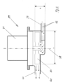
- the container has a circumferential seam which, in the final assembled state, is arranged circumferentially between the mutually facing edge edges of the two half parts of the second fresh water tank.
- the design of the heat exchanger described above is optimized overall in this respect designed so that, on the one hand, an optimized heat exchange takes place between the rinsing liquor to be discarded and the fresh water, and on the other hand, a sufficient volume is provided by the second fresh water tank so that it can store enough fresh water so that non-preheated fresh water can be supplied during the implementation a rinsing process is avoided.
- Fig. 17 shows a dishwasher 1 according to the prior art in a purely schematic representation.
- the dishwasher 1 has a housing, not shown in the figure, which, among other things, accommodates a washing container 2.
- the washing container 2 in turn provides a washing space 3, which, when used as intended, serves to hold items to be cleaned.
- a spray device 4 which is arranged within the washing container 2, is used to load the items to be cleaned with washing liquid.
- a spray device 4 preferably has spray arms 5, each of which is rotatably arranged within the washing container 2.
- the spray device 4 has a total of three spray arms 5, namely an upper spray arm, a middle spray arm and a lower spray arm.
- the washing chamber 3 opens into a collecting pot 6 of the washing container 2, to which one Circulation pump 7 is fluidly connected.
- the spray arms 5 of the spray device 4 are fluidly connected to the circulation pump 7 via corresponding supply lines 9, 10 and 11, with the interposition of a water switch 8.
- the spray device 4 can be charged with rinsing liquor by means of the circulation pump 7, with each After setting the water switch 8, either the upper and middle spray arm 5 or the lower spray arm 5 are charged with rinsing liquor.
- a wastewater pump 12 is also fluidly connected to the collecting pot 6 and, if necessary, pumps out the rinsing liquor located in the collecting pot 6 and feeds it to the wastewater line 13, as a result of which the rinsing liquor is discarded.
- the dishwasher 1 is also connected to a fresh water line 14.
- the fresh water line 14 is preceded by a softener in terms of flow, which is not shown in more detail in the figure.
- the fresh water line 14 opens into a changeover valve 15.
- a supply line 16 and a tank line 18 are provided on the output side of the switching valve 15. Depending on the position of the switching valve 15, either the supply line 16 or the tank line 18 can be served with fresh water.
- the feed line 16 opens into the collecting pot 6.
- fresh water flows directly into the collecting pot 6 via the fresh water line 14, the changeover valve 15 and the supply line 16.
- the tank line 18 opens into a fresh water tank 17. This is typically arranged next to the washing container 2 and is attached as a side tank to a side wall of the washing container 2.
- the fresh water tank 17 is in fluid communication with the supply line 16, namely by means of a line 22 designed approximately as a tube. This is fluidly connected to the fresh water tank 17 with the interposition of a valve 21 designed as a check valve.
- valve 21 If the valve 21 is in the blocking position, as shown in the figure, the Line 22 closed. According to this position of the check valve 21, no fresh water stored in the fresh water tank can flow through the line 22 into the supply line 16. When the check valve 21 is open, fresh water stored in the fresh water tank 17 passes through the line 22 and the supply line 16 into the collecting pot 6.
- the fresh water tank 17 is also in fluid communication with the washing chamber 3 provided by the washing container 2.
- the fresh water tank 17 has an overflow 19, which is followed by an overflow line 20 which opens into the washing chamber 3. If the fresh water tank 17 is overfilled with fresh water, it passes directly into the washing chamber 3 via the overflow 19 and the overflow line 20.
- the overflow line 20 also serves as a vent line for the fresh water tank 17.
- the fresh water tank 17 is used to be filled with fresh water after completing a washing program that has been carried out as intended.
- the fresh water stored in the fresh water tank 17 can warm up to room temperature by the time the next rinsing program is carried out, so that the heating energy required in the subsequent rinsing program to heat up the rinsing liquor is advantageously reduced.
- Fig. 1 shows a schematic representation of a dishwasher 1 designed according to the invention, in comparison to the prior art Fig. 17
- the same structural components of the dishwasher 1 have the same reference numbers.
- the dishwasher 1 according to the invention is characterized by a second fresh water tank 23. This is designed as a base tank and is arranged below the washing container 2.
- the first and second fresh water tanks 17 and 23 are in fluid communication.
- a pump 29 is integrated into this fluidic connection.
- a heat exchanger 24 is provided. This is housed by the second fresh water tank 23.
- the washing container 2 and the heat exchanger 24 are in a common, first Flow circuit 25 integrated, which flow circuit 25 serves to circulate the washing liquid.
- washing liquor can therefore be conveyed from the washing container 2 into the heat exchanger 24 and from there back into the washing container 2.
- the first fresh water tank 17 and the second fresh water tank 23 are integrated into a common second flow circuit 26, which flow circuit 26 serves to circulate fresh water.
- fresh water can slide from the first fresh water tank 17 into the second fresh water tank 23 and from there be guided back into the first fresh water tank 17.
- the second flow circuit 26, which fluidly connects the two fresh water tanks 17 and 23, is designed to be closed. It has a forward line 27 on the one hand and a return line 28 on the other.
- the outward line 27 leads from the first fresh water tank 17 to the second fresh water tank 23.
- the return line 28 is laid in the opposite direction to the outward line 27 and leads from the second fresh water tank 23 to the first fresh water tank 17.
- the pump 29 serving as a circulation pump is integrated into the return line 28 of the second flow circuit 26. If necessary, this serves to transfer fresh water from the fresh water tank 23, which is lower in the vertical direction, to the fresh water tank 17, which is upper in the vertical direction, by pumping.
- a changeover valve which is preferably the valve 21, is integrated into the outward line 27 of the second flow circuit 26. This adjoins the first fresh water tank 17 in the direction of flow and allows either the outward line 27 of the second flow circuit 26 or the line 22, which opens into the washing container 3 via the feed line 16 and is designed as a pipeline, to be selectively charged.
- the first fresh water tank 17 and second fresh water tank 23 can be filled as follows. Fresh water passes through the tank line 18 into the fresh water tank 1 via the fresh water line 14 and the changeover valve 15. The changeover valve 21 is connected to the outward line 27 of the flow circuit 26, so that the fresh water introduced into the first fresh water tank 17 passes through the fresh water tank 17 the second fresh water tank 23 flows. As soon as the second fresh water tank 23 is filled with fresh water, the first fresh water tank 17 also fills with fresh water. A supply of fresh water via the fresh water line 14 ends as soon as the first fresh water tank 17 is filled with fresh water.
- the first flow circuit 25, in which the washing container 2 and the heat exchanger 24 are integrated, is designed to be open.
- a free path leads through the washing container 2.
- a check valve 31 and 32 is provided on the input and output sides of the heat exchanger 24. With the interposition of the check valve 31, the heat exchanger 24 is connected to the water switch 8 on the input side. With the interposition of the check valve 32, the heat exchanger 24 is connected to the supply line 11 on the output side.
- the heat exchanger 24 With regard to the heat exchanger 24, the following operating modes are possible: With the check valves 31 and 32 closed, as shown in Fig. 1 is shown, the heat exchanger 24 is closed on both the input and output sides. It is not possible to charge the heat exchanger 24 with rinsing liquor. In this position of the check valves 31 and 32, when the circulation pump 7 is in operation, the spray arms 5 are charged with rinsing liquor via the supply lines 9, 10 and 11, with either the two upper spray arms 5 or the lower spray arm 5 depending on the position of the water switch 8 Rinsing liquor is supplied.
- the heat exchanger 24 can be charged with rinsing liquor if the water switch 8 is in the appropriate position, in which case the rinsing liquor after passing through the water switch 8 in the first Flow circuit 25 is circulated, that is, through the line 30, which is designed as a pipeline, it is led into the supply line 11 to the lower spray arm 5, delivered there via the lower spray arm 5 and returned to the collecting pot 6, from where it is then passed through again Circulation pump 7 is sucked in and fed back into line 30 via the water switch 8.
- the circulation pump 7 is only operated at a reduced speed. The circulated washing liquor is therefore subjected to only reduced pressure, so that it emerges from the lower spray arm 5 without spraying up to the items to be washed.
- the check valves 31 and 32 can be closed according to a third mode of operation if there is still washing liquor within the line 30. In this case, rinsing liquor is stored by the heat exchanger 24 until at least the check valve 32 is opened again to drain the stored rinsing liquor.
- the fresh water stored in the first and second fresh water tanks 17 and 23 is fed into the washing container 2 at the start of a cleaning program and the cleaning program is carried out. Meanwhile, the first and second fresh water tanks 17 and 23 are refilled with fresh water.
- washing liquor coming from the washing container 2 is passed through the first flow circuit 25 in circulation mode and, on the other hand, fresh water coming from the fresh water tanks 17 and 23 is passed through the second flow circuit 26 in circulation mode.
- hot rinsing liquor is still applied to the fresh water, which heats up the fresh water.
- the circulation operation is ended, at least with respect to the first flow circuit 25, and the check valves 31 and 32 provided on the inlet and outlet sides of the heat exchanger 24 are closed.
- the wastewater pump 12 is then switched on and the rinsing liquor located in the collecting pot is pumped out and fed to the wastewater line 13.
- the rinsing liquor stored by the heat exchanger 24 remains in the heat exchanger 24 with the check valves 31 and 32 still closed, and is therefore stored by it.
- fresh water stored in the first fresh water tank 17 is passed into the rinsing container 2 and the intermediate rinsing program is carried out.
- the fresh water stored in the first fresh water tank 17 is preheated due to the previously carried out heat transfer from the rinsing liquor to the fresh water.
- the first fresh water tank 17 is refilled with fresh water. While the intermediate rinsing program section is being carried out, the fresh water coming from the fresh water tanks 17 and 23 is passed through the second flow circuit 26 in circulation mode. In this respect, the fresh water from the fresh water tank 17, which is cold after refilling, and the preheated fresh water from the fresh water tank 23 are mixed. In addition, as a result of the circulation operation of the fresh water, there is a renewed transfer of heat from the rinsing liquor, which is still at least warm and stored by the heat exchanger 24, to that in the circulation operation Fresh water guided through the second flow circuit 26.
- the washing container 2 This is fed into the washing container 2 at the start of a final rinse program and a final rinse program is carried out.
- the first and second fresh water tanks 17 and 23 are also Fresh water is refilled so that the fresh water can warm up to room temperature until a new rinse program is carried out.
- Both the fresh water tank 23 and the heat exchanger 24 housed therein are connected to a ventilation line 33.
- This opens into the washing container 2, possibly with the interposition of the overflow line 20, which serves as a vent line for the first fresh water tank 17, as in Fig. 1 shown.
- the first fresh water tank 17 is equipped with insulation 34 and 35 on both sides of its two large areas.
- the insulation 34 is arranged between the fresh water tank 17 and the washing container 2.
- the insulation 34 or 35 ensures that after cold fresh water has been poured into the fresh water tank 17, no heat is withdrawn from the atmosphere surrounding the fresh water tank 17 and transferred to the fresh water stored in the fresh water tank 17. In particular, unwanted cooling of the associated side wall of the washing container 2 is avoided.
- the second fresh water tank 23 can also be equipped with appropriate insulation. However, a spaced arrangement of the second fresh water tank 23 from the washing container 2 is also preferred, so that no direct thermal bridge is formed between the second fresh water tank 23 and the washing container 2.
- Fig. 2 shows a schematic side view of the pump 29 integrated into the return line 28 of the second flow circuit 26.
- the pump 29 is a radial pump in a vertical orientation. In a manner known per se, it has a motor 36 and an impeller 37 driven by it during operation, which is arranged within a pump housing 41. During operation, the impeller 37 rotates about the axis of rotation 38, which is aligned vertically.
- the pump housing has a connecting piece 39 and a connecting piece 40, which serve to connect corresponding pipes of the second flow circuit 26.
- the pump 29 delivers fresh water in the second flow circuit 26 in circulation mode, that is, with interposition the two fresh water tanks 17 and 23 in the circuit, as shown by arrows 42 Fig. 2 is indicated.
- the pump 29 is aligned horizontally, the fresh water tank 23 would have to be arranged at least by the distance a above the base of the dishwasher, so that the impeller 37 is in the fresh water to be pumped even when the fresh water tank 23 is almost empty. Since the installation space in the base of the dishwasher should be used as much as possible, the pump 29 is as in Fig. 2 shown aligned vertically, with the pump housing 41 providing the impeller 37 being arranged below the motor 36 in the height direction. The distance b is decisive for the minimum distance between the underside of the fresh water tank 23 and the base floor.
- the distance dimension b is significantly smaller than the distance dimension a, when the pump 29 is aligned vertically, the bottom of the fresh water tank 23 can be significantly lower than when the pump 29 is aligned horizontally, so that the fresh water tank 23 provides a significantly larger filling volume.
- a corresponding advantage could also be achieved by designing the pump as an axial pump.
- the fresh water tank 23 and the heat exchanger 24 accommodated therein are designed in a special way, as shown in the following Figures 3 to 16 is described in detail.
- the design is optimized to the extent that, on the one hand, an optimized heat exchange can take place between the rinsing liquor to be discarded and the fresh water and, on the other hand, a sufficient tank volume is provided by the fresh water tank 23, so that enough fresh water can be stored in the fresh water tank 23 so that it can be supplied of non-preheated fresh water in an ongoing rinsing process is largely avoided.
- Fig. 3 shows the fresh water tank 23 and the heat exchanger 24 contained therein in a schematic side view.
- the fresh water tank 23 is designed as a container with an inlet 43 and an outlet 44.
- the design of the fresh water tank 23 as an injection molded part is preferred.
- a first and a second half part 49 and 50 are provided, which are connected to one another in the final assembled state, preferably welded to one another.
- the heat exchanger 24 arranged in the second fresh water tank 23 is a fluid-tight container. This is designed, for example, as a blow molded part. It has passage openings 45.
- the heat exchanger 24 divides the volume space 46 provided by the fresh water tank 23 into a first and a second compartment 47 and 48.
- the heat exchanger 24 is connected to the second fresh water tank 23 in a fluid-tight manner on the outer circumference.
- Fresh water flowing into the fresh water tank via the inlet 43 therefore first reaches the first compartment 47. From there, a flow through the flow openings 45 takes place, whereby the fresh water from the first compartment 47 reaches the second compartment 48. From there the fresh water then reaches outlet 44.
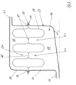
- Fig. 3 Furthermore, it can be seen that two opposing container sides of the heat exchanger 24 are brought together in sections and connected to one another with the respective formation of folds serving as channels 51.
- the passage openings 45 are formed in the area of the resulting connection points.
- the container forming the heat exchanger 24 has a circumferential seam 52, which in the case of a container designed as a blow-molded part is a pinch seam.
- the seam 52 is arranged all around between the mutually facing edge edges 53 and 54 of the two half parts 49 and 50.
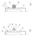
- the two half parts 49 and 50 are welded along their mutually facing edge edges 53 and 54 together with the seam 52 of the container serving as a heat exchanger 24 arranged between them. There is thus a fluid-tight connection between the two half parts 49 and 50 on the one hand and a fluid-tight edge-side connection between the second fresh water tank 23 and the container serving as a heat exchanger 24.
- a weld seam 55 shown as an example can be seen.
- connection between the fresh water tank 23 and the heat exchanger 24 by means of a connecting seam 56, as shown in Fig. 5 is shown. It is preferred to design the connecting seam 56 as an injection molded seam.
- Fig. 6 In a schematic representation, the flow of fresh water through the fresh water tank 23 can be seen using arrows 58 drawn as examples.
- the fresh water is guided in the second flow circuit 26 and reaches the fresh water tank 23 via the inlet 43. It flows through the first compartment 47 and then the second compartment 48 in the manner already described before it then returns to the pump 29 via the outlet 44.
- the heat exchanger 24 housed therein is washed around by the fresh water.
- the fresh water tank 23 has flow guide elements 57 on the inside.
- the flow guide ribs 57 are integrated into the upper half part 49 and have the function of distributing the water as evenly as possible above the heat exchanger 24.
- the bottom of the fresh water tank 23 is inclined towards the outlet 44 at an angle ⁇ , which is in particular at least four degrees.
- two supply lines 61 and 62 are also provided on the inlet side.
- the inlet 43 therefore has several supply lines, with two supply lines 61 and 62 in Fig. 7 are shown.
- Fig. 8 shows in a schematic representation using the arrows 63 that the container serving as a heat exchanger 24 is exposed to washing liquor.
- the container has several ports, with two of the ports in Fig. 8 can be seen, namely the connections 64 and 65.
- the rinsing liquor circulated in the first flow circuit 25 reaches the heat exchanger 24 via the connections 64 and 65. This flows through in accordance with the arrows 63, with the rinsing liquor returning to the heat exchanger 24 via the outlet 60 leaves.
- the container base 59 of the heat exchanger 24 is designed to be inclined, with the angle of inclination ⁇ in particular being at least five degrees.
- Fig. 9 shows the fresh water tank 23 in a perspective view.
- a first half part 49 there is a cover 67 and as a second half part 50, a base body 66 is provided. When fully assembled, these are welded together in the manner already described.
- Fig. 10 shows a schematic exploded view. It shows the base body 66, the heat exchanger 24 accommodated in the final assembled state and the cover 67 closing the base body 66.
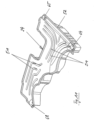
- the heat exchanger 24 is shown in a schematic perspective view in Fig. 11 shown. As can be seen from this illustration, the heat exchanger 24 has a total of three connections, namely the already mentioned connections 64 and 65 as well as the additional connection 68. The illustration according to Fig. 11 also shows channels 51 well.
- Fig. 12 shows a schematic top view from above of a heat exchanger 24 through which rinsing liquor flows.
- rinsing liquor flows into the heat exchanger 24 via the connections 64, 65 and 68 and is distributed here in accordance with the arrows 63.
- Fresh water circulated in the second flow circuit 26 flows separately from the rinsing liquor through the channels 51 and the flow openings 45 that fluidly connect the two compartments. This results in heat transfer from the rinsing liquor to the fresh water.
- the Figures 13 and 14 show the fresh water tank 23 in two different side views.
- the Figures 15 and 16 finally show a special design of the channels 51. It is then provided that the walls of the channels 51 are at least partially wave-shaped or corrugated, as is shown as an example in the area of section 69. This wavy or corrugated design creates an enlarged effective surface for heat transfer between the rinsing liquor and the fresh water.
- the design according to the invention makes it possible to transfer an increased amount of thermal energy from a first rinse cycle to several subsequent rinse cycles.
- the available installation space is used in an optimized manner by, on the one hand, providing a side tank as the first fresh water tank 17 and a base tank as the second fresh water tank 23. This maximizes the total usable volume of fresh water.
- the heat exchanger 24 which is designed as a container in the manner described above, has both the character of a heat storage tank and that of a flow-optimized channel geometry. This results in significant energy advantages.
- the internal volume is approximately four times larger and the entire heat exchanger surface is more than twice larger.
- the heat exchanger 24 is designed to be very compact overall. Therefore, the heat exchanger 23 can transfer significantly more heat energy to the fresh water of the wash cycles following a cleaning program than is the case with previously known heat recovery systems for dishwashers.
Landscapes
- Washing And Drying Of Tableware (AREA)
Claims (12)
- Lave-vaisselle, en particulier lave-vaisselle électroménager, comportant une cuve de lavage (2) fournissant un espace de lavage (3), laquelle cuve de lavage sert à recevoir des articles à laver, comportant un réservoir d'eau fraîche (17) disposé à côté de la cuve de lavage (2) en tant que réservoir latéral, lequel réservoir d'eau fraîche est raccordé à la cuve de lavage (2) par communication fluidique, et comportant un second réservoir d'eau fraîche (23) qui est disposé au-dessous de la cuve de lavage (2) en tant que réservoir de socle, dans lequel le premier et le second réservoir d'eau fraîche (17, 23) sont en liaison par communication fluidique, dans laquelle liaison est intégrée une pompe (29), de sorte que de l'eau fraîche peut circuler entre les deux réservoirs d'eau fraîche (17, 23) dans un fonctionnement de recirculation,et comportant un échangeur de chaleur (24) qui est en liaison par communication fluidique avec la cuve de lavage (2),caractérisé en ce quel'échangeur de chaleur (24) est une cuve étanche aux fluides disposée dans le second réservoir d'eau fraîche (23), lequel échangeur de chaleur peut être alimenté en bain de lavage provenant de la cuve de lavage (2),dans lequel, lorsque l'eau fraîche circule entre les deux réservoirs d'eau fraîche (17, 23) dans le fonctionnement de recirculation, la cuve est baignée par l'eau fraîche,et dans lequel la cuve présente des ouvertures d'écoulement (45) à travers lesquelles l'eau fraîche est menée.
- Lave-vaisselle selon la revendication 1, caractérisé en ce que la liaison par communication fluidique entre le premier et le second réservoir d'eau fraîche (17, 23) présente un circuit d'écoulement (26) qui est réalisé de manière à être fermé et dispose d'une conduite d'amenée (27) entre le premier et le second réservoir d'eau fraîche (17, 23) ainsi que d'une conduite de retour (28) entre le second et le premier réservoir d'eau fraîche (23, 17).
- Lave-vaisselle selon la revendication 2, caractérisé en ce que la pompe (29) est intégrée dans la conduite de retour (28).
- Lave-vaisselle selon l'une des revendications précédentes,
caractérisé en ce que la pompe (29) est une pompe axiale ou une pompe radiale dans un alignement vertical. - Lave-vaisselle selon l'une des revendications précédentes,
caractérisé en ce que la liaison par communication fluidique entre l'échangeur de chaleur (24) et la cuve de lavage (2) présente un circuit d'écoulement (25) qui est réalisé de manière à être ouvert et qui mène à travers la cuve de lavage (2), dans lequel est prévu, aussi bien du côté entrée que du côté sortie de l'échangeur de chaleur (24), respectivement un clapet antiretour (31, 32). - Lave-vaisselle selon l'une des revendications précédentes,
caractérisé en ce que la cuve divise l'espace volumétrique (46) fourni par le second réservoir d'eau fraîche (23) en un premier et en un second compartiment (47, 48), dans lequel la cuve est reliée de manière étanche aux fluides côté circonférence extérieure au second réservoir d'eau fraîche (23). - Lave-vaisselle selon l'une des revendications précédentes,
caractérisé en ce que le second réservoir d'eau fraîche (23) est réalisé en tant que pièce moulée par injection, dans lequel une première et une seconde demi-pièce (49, 50) sont prévues, lesquelles sont soudées l'une à l'autre côté circonférence. - Lave-vaisselle selon l'une des revendications précédentes,
caractérisé en ce que la cuve est réalisée en tant que pièce moulée par soufflage. - Lave-vaisselle selon l'une des revendications précédentes,
caractérisé en ce que deux côtés de cuve opposés l'un à l'autre sont réunis dans certaines sections et reliés l'un à l'autre en réalisant respectivement des plis servant de canaux (51), dans lequel un point de liaison est équipé d'une ouverture d'écoulement (45). - Lave-vaisselle selon l'une des revendications précédentes 7 à 9,
caractérisé en ce que la cuve présente une soudure (52) circonférentielle, de préférence une soudure sur bords tombés, qui est disposée, à l'état de montage final, de manière circonférentielle entre les bords marginaux (53, 54) tournés l'un vers l'autre des deux demi-pièces (49, 59) du second réservoir d'eau fraîche (23). - Lave-vaisselle selon la revendication 10, caractérisé en ce que les deux demi-pièces (49, 50) sont soudées le long de leurs bords marginaux (53, 54) tournés l'un vers l'autre, conjointement avec la soudure (52) de la cuve disposée entre elles.
- Lave-vaisselle selon la revendication 10, caractérisé en ce que la soudure (52) de la cuve fait saillie côté extérieur des demi-pièces (49, 50) et est équipée d'une soudure de liaison moulée par injection (56).
Applications Claiming Priority (2)
| Application Number | Priority Date | Filing Date | Title |
|---|---|---|---|
| DE102019118807.5A DE102019118807A1 (de) | 2019-07-11 | 2019-07-11 | Geschirrspülmaschine, insbesondere Haushaltsgeschirrspülmaschine |
| DE102019121748.2A DE102019121748A1 (de) | 2019-08-13 | 2019-08-13 | Geschirrspülmaschine |
Publications (2)
| Publication Number | Publication Date |
|---|---|
| EP3777638A1 EP3777638A1 (fr) | 2021-02-17 |
| EP3777638B1 true EP3777638B1 (fr) | 2024-02-14 |
Family
ID=71266509
Family Applications (1)
| Application Number | Title | Priority Date | Filing Date |
|---|---|---|---|
| EP20183888.5A Active EP3777638B1 (fr) | 2019-07-11 | 2020-07-03 | Lave-vaisselle |
Country Status (1)
| Country | Link |
|---|---|
| EP (1) | EP3777638B1 (fr) |
Families Citing this family (2)
| Publication number | Priority date | Publication date | Assignee | Title |
|---|---|---|---|---|
| EP4601522A1 (fr) * | 2022-10-12 | 2025-08-20 | Electrolux Appliances Aktiebolag | Machine de traitement d'articles avec ensemble réservoir |
| WO2024078709A1 (fr) * | 2022-10-12 | 2024-04-18 | Electrolux Appliances Aktiebolag | Machine de traitement d'articles avec ensemble réservoir |
Family Cites Families (6)
| Publication number | Priority date | Publication date | Assignee | Title |
|---|---|---|---|---|
| DE102009029115A1 (de) * | 2009-09-02 | 2011-03-03 | BSH Bosch und Siemens Hausgeräte GmbH | Geschirrspülmaschine sowie Verfahren zum Betrieb einer Geschirrspülmaschine |
| DE102011078730A1 (de) * | 2011-07-06 | 2013-01-10 | BSH Bosch und Siemens Hausgeräte GmbH | Geschirrspülmaschine |
| DE102011086788B4 (de) * | 2011-11-22 | 2025-11-20 | BSH Hausgeräte GmbH | Wasserführendes Haushaltsgerät, insbesondere Geschirrspülmaschine |
| DE102013213970B4 (de) | 2013-07-17 | 2017-03-09 | BSH Hausgeräte GmbH | Geschirrspülmaschine mit einem in einem Wasserbehälter integrierten Abflussrohrleitungsabschnitt sowie zugehöriges Verfahren |
| EP3095373B1 (fr) * | 2015-05-22 | 2020-01-22 | Vestel Beyaz Esya Sanayi Ve Ticaret A.S. | Dispositif de lavage et procédé de fonctionnement de celui-ci |
| DE102017120163A1 (de) * | 2017-09-01 | 2019-03-07 | Miele & Cie. Kg | Geschirrspülmaschine, insbesondere Haushaltsgeschirrspülmaschine |
-
2020
- 2020-07-03 EP EP20183888.5A patent/EP3777638B1/fr active Active
Also Published As
| Publication number | Publication date |
|---|---|
| EP3777638A1 (fr) | 2021-02-17 |
Similar Documents
| Publication | Publication Date | Title |
|---|---|---|
| DE102019121736B4 (de) | Geschirrspülmaschine und Verfahren zum Betrieb einer Geschirrspülmaschine | |
| EP0689791B1 (fr) | Lave-vaiselle avec un dispositif de récupération de chaleur des eaux usées | |
| DE102014202423B4 (de) | Spülmaschine | |
| EP3777637B1 (fr) | Lave-vaisselle, en particulier lave-vaisselle électroménager | |
| EP2292138B1 (fr) | Lave-vaisselle | |
| DE1812771B2 (de) | Geschirrspuelmaschine | |
| DE102014104373A1 (de) | Geschirrspülmaschine | |
| EP3777638B1 (fr) | Lave-vaisselle | |
| DE102014104369B4 (de) | Verfahren zur Rückgewinnung von Energie aus der Wärme von Spülflotte | |
| EP1878370A1 (fr) | Dispositif de nettoyage | |
| DE102015224723A1 (de) | Vorrichtung und Verfahren zur Wärmerückgewinnung aus Abwasser eines mit Warmwasser arbeitenden Geräts | |
| EP3675704B1 (fr) | Lave-vaisselle ménager pourvu de dispositif réservoir | |
| DE102019131958A1 (de) | Geschirrspülmaschine mit Wärmepumpe | |
| DE102022129366B4 (de) | Reinigungschemiebaugruppe für ein Gargerät und Gargerät mit einer solchen Baugruppe | |
| DE102019121748A1 (de) | Geschirrspülmaschine | |
| CH715427A1 (de) | Wasserführendes Haushaltsgerät mit Wärmerrückgewinnung. | |
| DE102017129052A1 (de) | Geschirrspülmaschine | |
| EP3406180B1 (fr) | Procédé de fonctionnement d'un appareil de nettoyage | |
| EP2679135B1 (fr) | Appareil ménager transportant de l'eau doté d'un récipient de stockage | |
| DE19946563B4 (de) | Geschirrspülmaschine mit einem Spülbehälter | |
| AT516597B1 (de) | Vorrichtung und Verfahren zur Wärmerückgewinnung aus Abwasser eines mit Warmwasser arbeitenden Geräts | |
| DE102011000759A1 (de) | Verfahren zum Füllen eines Behandlungsraums eines wasserführenden Haushaltgeräts | |
| EP3473155B1 (fr) | Lave-vaisselle | |
| DE102019218097A1 (de) | Energierückgewinnungstauscher | |
| EP2287384B1 (fr) | Appareil ménager transportant de l'eau |
Legal Events
| Date | Code | Title | Description |
|---|---|---|---|
| PUAI | Public reference made under article 153(3) epc to a published international application that has entered the european phase |
Free format text: ORIGINAL CODE: 0009012 |
|
| STAA | Information on the status of an ep patent application or granted ep patent |
Free format text: STATUS: THE APPLICATION HAS BEEN PUBLISHED |
|
| AK | Designated contracting states |
Kind code of ref document: A1 Designated state(s): AL AT BE BG CH CY CZ DE DK EE ES FI FR GB GR HR HU IE IS IT LI LT LU LV MC MK MT NL NO PL PT RO RS SE SI SK SM TR |
|
| AX | Request for extension of the european patent |
Extension state: BA ME |
|
| STAA | Information on the status of an ep patent application or granted ep patent |
Free format text: STATUS: REQUEST FOR EXAMINATION WAS MADE |
|
| 17P | Request for examination filed |
Effective date: 20210817 |
|
| RBV | Designated contracting states (corrected) |
Designated state(s): AL AT BE BG CH CY CZ DE DK EE ES FI FR GB GR HR HU IE IS IT LI LT LU LV MC MK MT NL NO PL PT RO RS SE SI SK SM TR |
|
| RIC1 | Information provided on ipc code assigned before grant |
Ipc: A47L 15/42 20060101AFI20230928BHEP |
|
| GRAP | Despatch of communication of intention to grant a patent |
Free format text: ORIGINAL CODE: EPIDOSNIGR1 |
|
| STAA | Information on the status of an ep patent application or granted ep patent |
Free format text: STATUS: GRANT OF PATENT IS INTENDED |
|
| INTG | Intention to grant announced |
Effective date: 20231116 |
|
| GRAS | Grant fee paid |
Free format text: ORIGINAL CODE: EPIDOSNIGR3 |
|
| GRAA | (expected) grant |
Free format text: ORIGINAL CODE: 0009210 |
|
| STAA | Information on the status of an ep patent application or granted ep patent |
Free format text: STATUS: THE PATENT HAS BEEN GRANTED |
|
| REG | Reference to a national code |
Ref country code: DE Ref legal event code: R084 Ref document number: 502020006985 Country of ref document: DE |
|
| AK | Designated contracting states |
Kind code of ref document: B1 Designated state(s): AL AT BE BG CH CY CZ DE DK EE ES FI FR GB GR HR HU IE IS IT LI LT LU LV MC MK MT NL NO PL PT RO RS SE SI SK SM TR |
|
| REG | Reference to a national code |
Ref country code: GB Ref legal event code: FG4D Free format text: NOT ENGLISH |
|
| REG | Reference to a national code |
Ref country code: CH Ref legal event code: EP |
|
| REG | Reference to a national code |
Ref country code: DE Ref legal event code: R096 Ref document number: 502020006985 Country of ref document: DE |
|
| REG | Reference to a national code |
Ref country code: IE Ref legal event code: FG4D Free format text: LANGUAGE OF EP DOCUMENT: GERMAN |
|
| REG | Reference to a national code |
Ref country code: GB Ref legal event code: 746 Effective date: 20240304 |
|
| REG | Reference to a national code |
Ref country code: LT Ref legal event code: MG9D |
|
| REG | Reference to a national code |
Ref country code: NL Ref legal event code: MP Effective date: 20240214 |
|
| PG25 | Lapsed in a contracting state [announced via postgrant information from national office to epo] |
Ref country code: IS Free format text: LAPSE BECAUSE OF FAILURE TO SUBMIT A TRANSLATION OF THE DESCRIPTION OR TO PAY THE FEE WITHIN THE PRESCRIBED TIME-LIMIT Effective date: 20240614 |
|
| PG25 | Lapsed in a contracting state [announced via postgrant information from national office to epo] |
Ref country code: LT Free format text: LAPSE BECAUSE OF FAILURE TO SUBMIT A TRANSLATION OF THE DESCRIPTION OR TO PAY THE FEE WITHIN THE PRESCRIBED TIME-LIMIT Effective date: 20240214 |
|
| PG25 | Lapsed in a contracting state [announced via postgrant information from national office to epo] |
Ref country code: GR Free format text: LAPSE BECAUSE OF FAILURE TO SUBMIT A TRANSLATION OF THE DESCRIPTION OR TO PAY THE FEE WITHIN THE PRESCRIBED TIME-LIMIT Effective date: 20240515 |
|
| PG25 | Lapsed in a contracting state [announced via postgrant information from national office to epo] |
Ref country code: RS Free format text: LAPSE BECAUSE OF FAILURE TO SUBMIT A TRANSLATION OF THE DESCRIPTION OR TO PAY THE FEE WITHIN THE PRESCRIBED TIME-LIMIT Effective date: 20240514 Ref country code: NL Free format text: LAPSE BECAUSE OF FAILURE TO SUBMIT A TRANSLATION OF THE DESCRIPTION OR TO PAY THE FEE WITHIN THE PRESCRIBED TIME-LIMIT Effective date: 20240214 Ref country code: HR Free format text: LAPSE BECAUSE OF FAILURE TO SUBMIT A TRANSLATION OF THE DESCRIPTION OR TO PAY THE FEE WITHIN THE PRESCRIBED TIME-LIMIT Effective date: 20240214 |
|
| PG25 | Lapsed in a contracting state [announced via postgrant information from national office to epo] |
Ref country code: ES Free format text: LAPSE BECAUSE OF FAILURE TO SUBMIT A TRANSLATION OF THE DESCRIPTION OR TO PAY THE FEE WITHIN THE PRESCRIBED TIME-LIMIT Effective date: 20240214 |
|
| PG25 | Lapsed in a contracting state [announced via postgrant information from national office to epo] |
Ref country code: RS Free format text: LAPSE BECAUSE OF FAILURE TO SUBMIT A TRANSLATION OF THE DESCRIPTION OR TO PAY THE FEE WITHIN THE PRESCRIBED TIME-LIMIT Effective date: 20240514 Ref country code: NO Free format text: LAPSE BECAUSE OF FAILURE TO SUBMIT A TRANSLATION OF THE DESCRIPTION OR TO PAY THE FEE WITHIN THE PRESCRIBED TIME-LIMIT Effective date: 20240514 Ref country code: NL Free format text: LAPSE BECAUSE OF FAILURE TO SUBMIT A TRANSLATION OF THE DESCRIPTION OR TO PAY THE FEE WITHIN THE PRESCRIBED TIME-LIMIT Effective date: 20240214 Ref country code: LT Free format text: LAPSE BECAUSE OF FAILURE TO SUBMIT A TRANSLATION OF THE DESCRIPTION OR TO PAY THE FEE WITHIN THE PRESCRIBED TIME-LIMIT Effective date: 20240214 Ref country code: IS Free format text: LAPSE BECAUSE OF FAILURE TO SUBMIT A TRANSLATION OF THE DESCRIPTION OR TO PAY THE FEE WITHIN THE PRESCRIBED TIME-LIMIT Effective date: 20240614 Ref country code: HR Free format text: LAPSE BECAUSE OF FAILURE TO SUBMIT A TRANSLATION OF THE DESCRIPTION OR TO PAY THE FEE WITHIN THE PRESCRIBED TIME-LIMIT Effective date: 20240214 Ref country code: GR Free format text: LAPSE BECAUSE OF FAILURE TO SUBMIT A TRANSLATION OF THE DESCRIPTION OR TO PAY THE FEE WITHIN THE PRESCRIBED TIME-LIMIT Effective date: 20240515 Ref country code: FI Free format text: LAPSE BECAUSE OF FAILURE TO SUBMIT A TRANSLATION OF THE DESCRIPTION OR TO PAY THE FEE WITHIN THE PRESCRIBED TIME-LIMIT Effective date: 20240214 Ref country code: ES Free format text: LAPSE BECAUSE OF FAILURE TO SUBMIT A TRANSLATION OF THE DESCRIPTION OR TO PAY THE FEE WITHIN THE PRESCRIBED TIME-LIMIT Effective date: 20240214 Ref country code: BG Free format text: LAPSE BECAUSE OF FAILURE TO SUBMIT A TRANSLATION OF THE DESCRIPTION OR TO PAY THE FEE WITHIN THE PRESCRIBED TIME-LIMIT Effective date: 20240214 |
|
| PG25 | Lapsed in a contracting state [announced via postgrant information from national office to epo] |
Ref country code: PL Free format text: LAPSE BECAUSE OF FAILURE TO SUBMIT A TRANSLATION OF THE DESCRIPTION OR TO PAY THE FEE WITHIN THE PRESCRIBED TIME-LIMIT Effective date: 20240214 Ref country code: PT Free format text: LAPSE BECAUSE OF FAILURE TO SUBMIT A TRANSLATION OF THE DESCRIPTION OR TO PAY THE FEE WITHIN THE PRESCRIBED TIME-LIMIT Effective date: 20240614 |
|
| PG25 | Lapsed in a contracting state [announced via postgrant information from national office to epo] |
Ref country code: SE Free format text: LAPSE BECAUSE OF FAILURE TO SUBMIT A TRANSLATION OF THE DESCRIPTION OR TO PAY THE FEE WITHIN THE PRESCRIBED TIME-LIMIT Effective date: 20240214 Ref country code: PT Free format text: LAPSE BECAUSE OF FAILURE TO SUBMIT A TRANSLATION OF THE DESCRIPTION OR TO PAY THE FEE WITHIN THE PRESCRIBED TIME-LIMIT Effective date: 20240614 Ref country code: PL Free format text: LAPSE BECAUSE OF FAILURE TO SUBMIT A TRANSLATION OF THE DESCRIPTION OR TO PAY THE FEE WITHIN THE PRESCRIBED TIME-LIMIT Effective date: 20240214 Ref country code: LV Free format text: LAPSE BECAUSE OF FAILURE TO SUBMIT A TRANSLATION OF THE DESCRIPTION OR TO PAY THE FEE WITHIN THE PRESCRIBED TIME-LIMIT Effective date: 20240214 |
|
| PG25 | Lapsed in a contracting state [announced via postgrant information from national office to epo] |
Ref country code: DK Free format text: LAPSE BECAUSE OF FAILURE TO SUBMIT A TRANSLATION OF THE DESCRIPTION OR TO PAY THE FEE WITHIN THE PRESCRIBED TIME-LIMIT Effective date: 20240214 |
|
| PG25 | Lapsed in a contracting state [announced via postgrant information from national office to epo] |
Ref country code: SM Free format text: LAPSE BECAUSE OF FAILURE TO SUBMIT A TRANSLATION OF THE DESCRIPTION OR TO PAY THE FEE WITHIN THE PRESCRIBED TIME-LIMIT Effective date: 20240214 |
|
| PG25 | Lapsed in a contracting state [announced via postgrant information from national office to epo] |
Ref country code: CZ Free format text: LAPSE BECAUSE OF FAILURE TO SUBMIT A TRANSLATION OF THE DESCRIPTION OR TO PAY THE FEE WITHIN THE PRESCRIBED TIME-LIMIT Effective date: 20240214 Ref country code: EE Free format text: LAPSE BECAUSE OF FAILURE TO SUBMIT A TRANSLATION OF THE DESCRIPTION OR TO PAY THE FEE WITHIN THE PRESCRIBED TIME-LIMIT Effective date: 20240214 |
|
| PG25 | Lapsed in a contracting state [announced via postgrant information from national office to epo] |
Ref country code: SK Free format text: LAPSE BECAUSE OF FAILURE TO SUBMIT A TRANSLATION OF THE DESCRIPTION OR TO PAY THE FEE WITHIN THE PRESCRIBED TIME-LIMIT Effective date: 20240214 |
|
| PG25 | Lapsed in a contracting state [announced via postgrant information from national office to epo] |
Ref country code: SM Free format text: LAPSE BECAUSE OF FAILURE TO SUBMIT A TRANSLATION OF THE DESCRIPTION OR TO PAY THE FEE WITHIN THE PRESCRIBED TIME-LIMIT Effective date: 20240214 Ref country code: SK Free format text: LAPSE BECAUSE OF FAILURE TO SUBMIT A TRANSLATION OF THE DESCRIPTION OR TO PAY THE FEE WITHIN THE PRESCRIBED TIME-LIMIT Effective date: 20240214 Ref country code: RO Free format text: LAPSE BECAUSE OF FAILURE TO SUBMIT A TRANSLATION OF THE DESCRIPTION OR TO PAY THE FEE WITHIN THE PRESCRIBED TIME-LIMIT Effective date: 20240214 Ref country code: EE Free format text: LAPSE BECAUSE OF FAILURE TO SUBMIT A TRANSLATION OF THE DESCRIPTION OR TO PAY THE FEE WITHIN THE PRESCRIBED TIME-LIMIT Effective date: 20240214 Ref country code: DK Free format text: LAPSE BECAUSE OF FAILURE TO SUBMIT A TRANSLATION OF THE DESCRIPTION OR TO PAY THE FEE WITHIN THE PRESCRIBED TIME-LIMIT Effective date: 20240214 Ref country code: CZ Free format text: LAPSE BECAUSE OF FAILURE TO SUBMIT A TRANSLATION OF THE DESCRIPTION OR TO PAY THE FEE WITHIN THE PRESCRIBED TIME-LIMIT Effective date: 20240214 |
|
| REG | Reference to a national code |
Ref country code: DE Ref legal event code: R097 Ref document number: 502020006985 Country of ref document: DE |
|
| PG25 | Lapsed in a contracting state [announced via postgrant information from national office to epo] |
Ref country code: IT Free format text: LAPSE BECAUSE OF FAILURE TO SUBMIT A TRANSLATION OF THE DESCRIPTION OR TO PAY THE FEE WITHIN THE PRESCRIBED TIME-LIMIT Effective date: 20240214 |
|
| PLBE | No opposition filed within time limit |
Free format text: ORIGINAL CODE: 0009261 |
|
| STAA | Information on the status of an ep patent application or granted ep patent |
Free format text: STATUS: NO OPPOSITION FILED WITHIN TIME LIMIT |
|
| PG25 | Lapsed in a contracting state [announced via postgrant information from national office to epo] |
Ref country code: IT Free format text: LAPSE BECAUSE OF FAILURE TO SUBMIT A TRANSLATION OF THE DESCRIPTION OR TO PAY THE FEE WITHIN THE PRESCRIBED TIME-LIMIT Effective date: 20240214 |
|
| 26N | No opposition filed |
Effective date: 20241115 |
|
| PG25 | Lapsed in a contracting state [announced via postgrant information from national office to epo] |
Ref country code: MC Free format text: LAPSE BECAUSE OF FAILURE TO SUBMIT A TRANSLATION OF THE DESCRIPTION OR TO PAY THE FEE WITHIN THE PRESCRIBED TIME-LIMIT Effective date: 20240214 |
|
| REG | Reference to a national code |
Ref country code: CH Ref legal event code: PL |
|
| PG25 | Lapsed in a contracting state [announced via postgrant information from national office to epo] |
Ref country code: LU Free format text: LAPSE BECAUSE OF NON-PAYMENT OF DUE FEES Effective date: 20240703 |
|
| PG25 | Lapsed in a contracting state [announced via postgrant information from national office to epo] |
Ref country code: LU Free format text: LAPSE BECAUSE OF NON-PAYMENT OF DUE FEES Effective date: 20240703 |
|
| PG25 | Lapsed in a contracting state [announced via postgrant information from national office to epo] |
Ref country code: SI Free format text: LAPSE BECAUSE OF FAILURE TO SUBMIT A TRANSLATION OF THE DESCRIPTION OR TO PAY THE FEE WITHIN THE PRESCRIBED TIME-LIMIT Effective date: 20240214 Ref country code: CH Free format text: LAPSE BECAUSE OF NON-PAYMENT OF DUE FEES Effective date: 20240731 Ref country code: BE Free format text: LAPSE BECAUSE OF NON-PAYMENT OF DUE FEES Effective date: 20240731 |
|
| REG | Reference to a national code |
Ref country code: BE Ref legal event code: MM Effective date: 20240731 |
|
| PG25 | Lapsed in a contracting state [announced via postgrant information from national office to epo] |
Ref country code: IE Free format text: LAPSE BECAUSE OF NON-PAYMENT OF DUE FEES Effective date: 20240703 |
|
| PGFP | Annual fee paid to national office [announced via postgrant information from national office to epo] |
Ref country code: DE Payment date: 20250731 Year of fee payment: 6 |
|
| PGFP | Annual fee paid to national office [announced via postgrant information from national office to epo] |
Ref country code: GB Payment date: 20250722 Year of fee payment: 6 |
|
| PGFP | Annual fee paid to national office [announced via postgrant information from national office to epo] |
Ref country code: FR Payment date: 20250725 Year of fee payment: 6 Ref country code: AT Payment date: 20251020 Year of fee payment: 5 |
|
| PG25 | Lapsed in a contracting state [announced via postgrant information from national office to epo] |
Ref country code: CY Free format text: LAPSE BECAUSE OF FAILURE TO SUBMIT A TRANSLATION OF THE DESCRIPTION OR TO PAY THE FEE WITHIN THE PRESCRIBED TIME-LIMIT; INVALID AB INITIO Effective date: 20200703 |
|
| PG25 | Lapsed in a contracting state [announced via postgrant information from national office to epo] |
Ref country code: HU Free format text: LAPSE BECAUSE OF FAILURE TO SUBMIT A TRANSLATION OF THE DESCRIPTION OR TO PAY THE FEE WITHIN THE PRESCRIBED TIME-LIMIT; INVALID AB INITIO Effective date: 20200703 |