EP3777655B1 - Testvorrichtung zur analyse von körperflüssigkeiten - Google Patents
Testvorrichtung zur analyse von körperflüssigkeiten Download PDFInfo
- Publication number
- EP3777655B1 EP3777655B1 EP19854459.5A EP19854459A EP3777655B1 EP 3777655 B1 EP3777655 B1 EP 3777655B1 EP 19854459 A EP19854459 A EP 19854459A EP 3777655 B1 EP3777655 B1 EP 3777655B1
- Authority
- EP
- European Patent Office
- Prior art keywords
- assembly
- body fluid
- test device
- guide
- coupling
- Prior art date
- Legal status (The legal status is an assumption and is not a legal conclusion. Google has not performed a legal analysis and makes no representation as to the accuracy of the status listed.)
- Active
Links
Images


Classifications
-
- A—HUMAN NECESSITIES
- A61—MEDICAL OR VETERINARY SCIENCE; HYGIENE
- A61B—DIAGNOSIS; SURGERY; IDENTIFICATION
- A61B5/00—Measuring for diagnostic purposes; Identification of persons
- A61B5/145—Measuring characteristics of blood in vivo, e.g. gas concentration or pH-value ; Measuring characteristics of body fluids or tissues, e.g. interstitial fluid or cerebral tissue
- A61B5/14507—Measuring characteristics of blood in vivo, e.g. gas concentration or pH-value ; Measuring characteristics of body fluids or tissues, e.g. interstitial fluid or cerebral tissue specially adapted for measuring characteristics of body fluids other than blood
-
- A—HUMAN NECESSITIES
- A61—MEDICAL OR VETERINARY SCIENCE; HYGIENE
- A61B—DIAGNOSIS; SURGERY; IDENTIFICATION
- A61B5/00—Measuring for diagnostic purposes; Identification of persons
- A61B5/0059—Measuring for diagnostic purposes; Identification of persons using light, e.g. diagnosis by transillumination, diascopy, fluorescence
-
- A—HUMAN NECESSITIES
- A61—MEDICAL OR VETERINARY SCIENCE; HYGIENE
- A61B—DIAGNOSIS; SURGERY; IDENTIFICATION
- A61B10/00—Instruments for taking body samples for diagnostic purposes; Other methods or instruments for diagnosis, e.g. for vaccination diagnosis, sex determination or ovulation-period determination; Throat striking implements
- A61B10/0045—Devices for taking samples of body liquids
-
- A—HUMAN NECESSITIES
- A61—MEDICAL OR VETERINARY SCIENCE; HYGIENE
- A61B—DIAGNOSIS; SURGERY; IDENTIFICATION
- A61B10/00—Instruments for taking body samples for diagnostic purposes; Other methods or instruments for diagnosis, e.g. for vaccination diagnosis, sex determination or ovulation-period determination; Throat striking implements
- A61B10/0045—Devices for taking samples of body liquids
- A61B10/0051—Devices for taking samples of body liquids for taking saliva or sputum samples
-
- A—HUMAN NECESSITIES
- A61—MEDICAL OR VETERINARY SCIENCE; HYGIENE
- A61B—DIAGNOSIS; SURGERY; IDENTIFICATION
- A61B5/00—Measuring for diagnostic purposes; Identification of persons
- A61B5/145—Measuring characteristics of blood in vivo, e.g. gas concentration or pH-value ; Measuring characteristics of body fluids or tissues, e.g. interstitial fluid or cerebral tissue
- A61B5/1455—Measuring characteristics of blood in vivo, e.g. gas concentration or pH-value ; Measuring characteristics of body fluids or tissues, e.g. interstitial fluid or cerebral tissue using optical sensors, e.g. spectral photometrical oximeters
-
- A—HUMAN NECESSITIES
- A61—MEDICAL OR VETERINARY SCIENCE; HYGIENE
- A61B—DIAGNOSIS; SURGERY; IDENTIFICATION
- A61B5/00—Measuring for diagnostic purposes; Identification of persons
- A61B5/43—Detecting, measuring or recording for evaluating the reproductive systems
- A61B5/4375—Detecting, measuring or recording for evaluating the reproductive systems for evaluating the male reproductive system
-
- A—HUMAN NECESSITIES
- A61—MEDICAL OR VETERINARY SCIENCE; HYGIENE
- A61B—DIAGNOSIS; SURGERY; IDENTIFICATION
- A61B5/00—Measuring for diagnostic purposes; Identification of persons
- A61B5/68—Arrangements of detecting, measuring or recording means, e.g. sensors, in relation to patient
- A61B5/6887—Arrangements of detecting, measuring or recording means, e.g. sensors, in relation to patient mounted on external non-worn devices, e.g. non-medical devices
- A61B5/6898—Portable consumer electronic devices, e.g. music players, telephones, tablet computers
-
- G—PHYSICS
- G01—MEASURING; TESTING
- G01N—INVESTIGATING OR ANALYSING MATERIALS BY DETERMINING THEIR CHEMICAL OR PHYSICAL PROPERTIES
- G01N21/00—Investigating or analysing materials by the use of optical means, i.e. using sub-millimetre waves, infrared, visible or ultraviolet light
- G01N21/17—Systems in which incident light is modified in accordance with the properties of the material investigated
-
- G—PHYSICS
- G01—MEASURING; TESTING
- G01N—INVESTIGATING OR ANALYSING MATERIALS BY DETERMINING THEIR CHEMICAL OR PHYSICAL PROPERTIES
- G01N33/00—Investigating or analysing materials by specific methods not covered by groups G01N1/00 - G01N31/00
- G01N33/48—Biological material, e.g. blood, urine; Haemocytometers
- G01N33/483—Physical analysis of biological material
- G01N33/487—Physical analysis of biological material of liquid biological material
-
- H—ELECTRICITY
- H04—ELECTRIC COMMUNICATION TECHNIQUE
- H04M—TELEPHONIC COMMUNICATION
- H04M1/00—Substation equipment, e.g. for use by subscribers
- H04M1/02—Constructional features of telephone sets
- H04M1/21—Combinations with auxiliary equipment, e.g. with clocks or memoranda pads
-
- G—PHYSICS
- G01—MEASURING; TESTING
- G01N—INVESTIGATING OR ANALYSING MATERIALS BY DETERMINING THEIR CHEMICAL OR PHYSICAL PROPERTIES
- G01N2201/00—Features of devices classified in G01N21/00
- G01N2201/06—Illumination; Optics
- G01N2201/063—Illuminating optical parts
Definitions
- the present disclosure relates to a test device for a body fluid, and more particularly, to a test device for analyzing a body fluid allowing a user to directly test a body fluid without restriction of place or time and check an analysis result of the body fluid through a user terminal.
- test device is disclosed in US 2016/290916 A1 .
- the said test device comprises a first assembly having a lens for observing semen.
- a second assembly is configured to be coupled to the first assembly.
- an Observation sheet is shown for receiving the semen between the first assembly and the second assembly.
- Such a test device detects biochemical substances such as hormones released in specific situations using secretions or body fluids, such as saliva, urine, sweat, blood, or sperm, discharged from the human body, which has advantages of relatively high accuracy and ease of use and is mainly used as a test means such as pregnancy diagnosis, diabetes diagnosis, or blood sugar check.
- a pregnancy test device may only determine a pregnancy Status and is not helpful for users suffering from sterility and infertility. Moreover, even such a pregnancy test device may only determine a woman's pregnancy and matters such as a woman's possibility of pregnancy and a man's ability to fertilize may be limitedly verified at specialized medical institutions.
- a sperm test to check man's fertilizing power requires a man to ejaculate a semen sample in a laboratory, which may make him feel ashamed shy, and if he collects a sperm sample at home, he may be requested to quickly bring it a laboratory, which may risk sperm death during transport.
- An aspect of the present disclosure provides a test device for body fluid analysis that the user may simply carry around and use conveniently, so that the user may directly perform a body fluid test at a desired place and time and immediately check an analysis result of a body fluid through a user terminal.
- present disclosure includes any other objects that may be achieved from the configuration of the present disclosure described later, in addition to the explicitly mentioned object.
- test device for a body fluid analysis according to claim 1.
- the handle part may be disposed in an outer space of the first assembly and the second assembly.
- the first assembly may further include a first communication hole connecting the seating recess and the external space.
- the magnifying lens may be installed in the seating recess.
- the first assembly may further include a first circumferential step formed along an outer edge of the first assembly body to guide assembly according to coupling with the second assembly.
- the second assembly may further include a second assembly body and at least one coupling protrusion formed on a lower surface of the second assembly body so as to be coupled with the at least one coupling recess.
- the second assembly may further include a second communication hole formed in the second assembly body so that the handle part of the Observation sheet is disposed in an external space.
- the lens transmission hole may penetrate from an upper side to a lower side of the second assembly body.
- the second assembly may further include a second circumferential protrusion formed to be stepped along an outer edge of the second assembly body to guide assembly according to coupling with the first assembly.
- the body part includes a body fluid input part formed to allow the target body fluid to be injected thereinto and a body fluid guide part configured to guide the target body fluid injected into the body fluid input part so as to be observed in a field of view of the magnifying lens.
- the body fluid input part may include at least one body fluid guide recess formed in the body part to guide injection of the target body fluid.
- the first assembly may be detachably attached to a camera of a user terminal.
- the test device for a body fluid analysis may be simply carried around and conveniently used by the user and easily detachably attached to a camera portion of a user terminal. Therefore, the user may directly perform a test at a desired place and time and immediately check an analysis result of a body fluid through a user terminal
- test device for a body fluid analysis may be used by both women and men. That is, women may check their ovulation period to check a time with a high chance of pregnancy and men may check their sperm Status, thereby increasing a likelihood of pregnancy.
- the test device for a body fluid analysis may be easily attached and may be uniformly attached around a camera.
- the handle part that may be gripped by the user is provided on the Observation sheet accommodating the body fluid, contamination of the body fluid by the user may be prevented and the Observation sheet may be easily seated inside the test device for a body fluid analysis and separated therefrom.
- the effects of the present disclosure are not limited to those described above and other effects that may be derived from the configuration of the present disclosure described later are included in the effects of the present disclosure.
- FIG. 1 is a view of a test device for a body fluid analysis mounted on a user terminal according to an embodiment of the present disclosure
- FIG. 2 is an exploded perspective view of a test device for a body fluid analysis according to an embodiment of the present disclosure.
- a test device 1 for a body fluid analysis may image a target body fluid through a camera 11 of a user terminal 10 to generate a body fluid image, and a result of analyzing the body fluid image may be checked through the user terminal 10.
- the user terminal 10 may analyze the body fluid image through a preinstalled analysis program or analysis application and Output the analyzed result so that the analyzed result may be provided to a user or may be transferred to a Professional examination Institution.
- the test device 1 for a body fluid analysis includes a first assembly 100 detachably installed to the camera 11 of the user terminal 10, a second assembly 200 coupled to the first assembly 100, and an Observation sheet 300 accommodating a target body fluid between the first assembly 100 and the second assembly 200.
- the first assembly 100 is detachably installed to the camera 11 of the user terminal 10 and is configured so that the camera 11 may image the target body fluid.
- the first assembly 100 may be attached to a portion near the camera 11 of the user terminal by an adhesive or may be selectively attached to or removed from the user terminal 10 through a separate mounting member formed in the form of a clip.
- the mounting member is not limited to the clip form and may have any other various forms that may be attached to the user terminal 10.
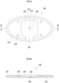
- FIG. 3A is a plan view of a first assembly according to an embodiment of the present disclosure and FIG. 3B is an enlarged cross-sectional view taken along line A-A of FIG. 3A .
- the first assembly 100 may include a first assembly body 110 as a flat plate, a seating recess formed to allow the Observation sheet 300 to be seated on an inner side of the first assembly body 110, a through hole 130 formed in the seating recess 120 and penetrating the first assembly body 110, a first communication hole 140 connecting the seating recess 120 and the external space, and at least one coupling recess 150 formed on an upper surface of the first assembly body 110 so as to be assembled with the second assembly 200.
- the first assembly body 110 may protect the target body fluid from an external shock or contamination and may be formed of a material which is strong against an external impact and light in weight, such as synthetic resin or a metal so that the camera 11 of the user terminal 10 may stably image the target body fluid.
- an outer surface of the first assembly body 110 may be colored with non-transmissive paint or formed of an opaque material so that light may be transmitted only in a limited portion.
- the seating recess 120 may be formed as a recess having a certain width at the center of an upper surface of the first assembly body 110.
- the seating recess 120 may be formed as a recess having a shape corresponding to the Observation sheet 300, thereby stably supporting the Observation sheet 300 and fixing the Observation sheet 300 not to wobble, when the Observation sheet 300 is seated therein.
- the through hole 130 is formed at the center of the seating recess 120 and penetrates the first assembly body 110. Wien attached to the user terminal 11, the test device 1 for a body fluid analysis may be located in a direction facing the camera 11 to image the target body fluid accommodated in the Observation sheet 300 through the through hole 130.
- the first communication hole 140 may be formed to pass through an edge portion of the first assembly body 110 to connect the seating recess 120 and an external space.
- the first communication hole 140 may allow the handle part 320 of the Observation sheet 300 to be described below to be seated therein and may have a shape corresponding to a cross section of the handle part 320.
- At least one coupling recess 150 may be formed on an upper surface of the first assembly body 110 and may be coupled with a coupling protrusion 240 of the second assembly 200 to be described below to assemble the first assembly 100 and the second assembly 200.
- the two coupling protrusions 240 may be provided on left and right sides of an upper surface of the first assembly body 110 and may be coupled with two coupling protrusions 240 provided at the second assembly 200, respectively.
- the first assembly 100 may further include a magnifying lens 160 installed at the center of an inner side of the first assembly body 110, in particular, at the center of the seating recess 120 in which the Observation sheet 300 is seated.
- a pinhole effect may be obtained because the target body fluid may be magnified.
- the pinhole effect is a phenomenon in which an object is visible relatively clearly when viewed through a small hole, and since light entering through the lens transmission hole 220 of the second assembly 200 to be described below enters in a straight line without having to be collected to one place, an exact image may be formed so that the target body fluid may be observed clearly.
- the magnifying lens 160 compensates for an insufficient magnification ratio in the camera 11 of the user terminal 10 so that the target body fluid may be sufficiently magnified to be observed.
- first assembly 100 may further include a first circumferential step 170 formed to be stepped along an outer edge of the first assembly body 110 to guide assembly according to coupling with the second assembly 200. Accordingly, reinforcing may be provided in response to horizontal pushing when the first assembly 100 and the second assembly 200 may are assembled, and since positions of the first assembly 100 and the second assembly 200 according to coupling may be easily secured, assembling may be easily performed.
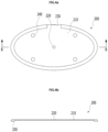
- FIG. 4A is a plan view of a second assembly according to an embodiment of the present disclosure
- FIG. 4B is an enlarged cross-sectional view taken along line B-B shown in FIG. 4A .
- the second assembly 200 may be configured to be assembled to an upper side of the first assembly 100 and may include a second assembly body 210 as a flat plate, a lens transmission hole 220 for concentrating light, a second communication hole 230 formed at the second assembly body 210, and at least one coupling protrusion 240 provided on a lower surface of the second assembly body 210 so as to be coupled with the coupling recess 150 of the first assembly 100.
- the second assembly body 210 may protect the target body fluid from an external impact or contamination and may be formed of a material which is strong against an external impact and is light in weight such as a synthetic resin or a metal to stably image the target body fluid.
- an outer surface of the second assembly body 210 may be colored with non-transmissive paint or formed of an opaque material so that light may be transmitted only in a limited portion.
- the lens transmission hole 220 may be a narrow vertical hole and may penetrate from an upper center of the second assembly body 210 to a lower side, and a periphery of the upper surface of the penetrated second assembly body 210 may be coated in black. Accordingly, more light may be absorbed to the narrow hole under the influence of black which absorbs light well.
- the second communication hole 230 may be formed at a position corresponding to the first communication hole 140 and penetrates an edge portion of the second assembly body 210. That is, the second communication hole 230 may be formed in the second assembly body 210 so that the handle part 320 of the Observation sheet 300 is disposed in an external space. Specifically, the second communication hole 230 may be configured to allow the handle part of the Observation sheet 300 to be described below to be seated therein and may have a shape corresponding to a cross-section of the handle part 320. At least one coupling protrusion 240 may be formed to protrude from a lower surface of the second assembly body 210 and may be coupled to at least one coupling recess 150.
- the two coupling protrusions 240 may be provided on left and right sides of a lower surface of the second assembly body 210 and installed at positions corresponding to the coupling recesses 150, so that the coupling protrusions 240 may be inserted into the coupling recesses 150, respectively, when the first assembly 100 and the second assembly 200 are coupled.
- the second assembly 200 may further include a second circumferential protrusion 250 formed to be stepped along an outer edge of the second assembly body 210 to guide assembly according to coupling with the first assembly 100.
- the first circumferential step 170 installed on the edge of the first assembly 100 and the second circumferential protrusion 250 installed on the edge of the second assembly 200 may be installed to be coupled to correspond to each other, the first assembly 100 and the second assembly 200 may be easily assembled without adjusting a position according to the coupling of the first assembly 100 and the second assembly 200.
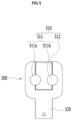
- FIG. 5 is a plan view of an Observation sheet according to an embodiment of the present disclosure.
- the Observation sheet 300 serves as a stage which a target body fluid to be inspected is applied to and which allows the camera 11 of the user terminal 10 to image the target body fluid.
- the Observation sheet 300 may include a body part 310 accommodating the target body fluid and a handle part 320 extending from the body part 310.
- the body part 310 may accommodate a certain amount of the target body fluid and may be formed as a thin plate.
- the body part 310 may be formed of a transparent material, such as a synthetic resin material including polycarbonate, polyethylene, or acrylic material or a glass material in order to allow light to be transmitted therethrough and to obtain a clear image.
- the body part 310 may be colored with a single color or a complementary color of the target body fluid so that the target body fluid may be clearly observed, or a film may be attached to one surface thereof.
- the body part 310 may include a body fluid input part 311 allowing the target body fluid to be injected therein and a body fluid guide part 312 guiding the target body fluid injected into the body fluid input part 311 to be observed in the field of view of the magnifying lens 160.
- the body fluid input part 311 may include at least one body fluid guide recess 311a and 311b formed in the body part 310 to guide the input of the target body fluid.
- the body fluid input part 311 may include a pair of body fluid guide recesses 311a and 311b respectively formed on left and right sides of the body part 310.
- the body fluid guide part 312 may be inserted as a flat plate into the center of the body part 310 so that the target body fluid permeates an inner side of the center so as to be observed in the field of view of the magnifying lens 160, while protecting the target body fluid injected into the body fluid inlet 311.
- the body fluid guide part 312 may be formed higher than a bottom of the body fluid input part 311 and maintain a certain distance from the lens transmission hole 220 of the second assembly 200.
- the target body fluid may permeate the inner side of the center of the body fluid guide part 312 from the body fluid guide recesses 311a and 311b.
- an upper surface of the body fluid guide part 312 which is as a surface capable of absorbing a liquid, may be formed of a material such as paper or a porous synthetic resin, so that a predetermined amount of the target body fluid may be absorbed thereto.
- the handle part 320 may extend from the body part 310 and may be disposed at an outer space of the first assembly 100 and the second assembly 200.
- the handle part 320 may be configured to be gripped by a user to easily insert the body part 310 into or remove the body part 310 from the seating recess 120 of the first assembly 100.
- the handle part 320 may be formed of the same material as the body part 310 but is not limited thereto. In this manner, by implementing the handle part 320 on the Observation sheet 300, the target body fluid may be prevented from being contaminated by the user and the Observation sheet 300 is easily seated inside the test device 1 for a body fluid analysis or separated therefrom.
- a direction indicator may be provided on the handle part 320 so that the user may easily check an input direction of the Observation sheet 300.
- the handle part 320 may be disposed in an internal space of the first assembly 100 and the second assembly 200. That is, when the seating recess 120 is formed to have the same shape as a plane of the Observation sheet 300, the handle part 320 may be seated inside the first assembly 100 and the second assembly 200 together with the body part 310. In this manner, when the body part 310 and the handle part 320 are disposed at the internal space of the first assembly 100 and the second assembly 200, the first assembly 100 and the second assembly 200 may not have the first communication hole 140 and the second communication hole 230.
- the first assembly 100 may be installed so that the through hole 130 is located in a direction facing the camera 11 of the user terminal 10 and light is controlled to be concentrated through the lens transmission hole 220 of the second assembly 200, whereby the target body fluid accommodated in the Observation sheet 300 may be clearly observed through the magnifying lens 160.
- the first assembly 100 of the test device 1 for a body fluid analysis is mounted or attached to an upper side of the camera 11 of the user terminal 10, and the Observation sheet 300 is subsequently seated in the seating recess 120 of the first assembly 100.
- a target body fluid may be dropped onto the body fluid input part 311 of the Observation sheet 300 seated in the first assembly 100, and the second assembly 200 is subsequently coupled to an upper side of the first assembly 100, thereby finishing assembling.
- the Observation sheet 300 in which the target body fluid is accommodated may be first seated in the seating recess 120 of the first assembly 100, the first assembly 100 in which the Observation sheet is seated and the second assembly 200 may be coupled to be assembled, and thereafter, the test device for a body fluid analysis to which the first assembly 100 and the second assembly 200 may be mounted on or attached to the user terminal 10.
- a program or application dedicated to a body fluid analysis test of the user terminal 10 may be executed to observe and image the target body fluid accommodated in the Observation sheet 300 through the camera 11, thereby performing the body fluid analysis test process.
- test device 1 for a body fluid analysis may be simply carried around by the user and collect only a target body fluid and apply the collected target body fluid to the test device, and thus the user may directly perform the body fluid test, and since the user may immediately check a result of analyzing the body fluid through the user terminal, user convenience may be improved and an accurate test result may be provided to the user.
Landscapes
- Health & Medical Sciences (AREA)
- Life Sciences & Earth Sciences (AREA)
- Engineering & Computer Science (AREA)
- Biomedical Technology (AREA)
- Physics & Mathematics (AREA)
- Pathology (AREA)
- General Health & Medical Sciences (AREA)
- Molecular Biology (AREA)
- Surgery (AREA)
- Medical Informatics (AREA)
- Veterinary Medicine (AREA)
- Public Health (AREA)
- Heart & Thoracic Surgery (AREA)
- Animal Behavior & Ethology (AREA)
- Biophysics (AREA)
- Chemical & Material Sciences (AREA)
- Hematology (AREA)
- General Physics & Mathematics (AREA)
- Immunology (AREA)
- Biochemistry (AREA)
- Analytical Chemistry (AREA)
- Urology & Nephrology (AREA)
- Medicinal Chemistry (AREA)
- Food Science & Technology (AREA)
- Optics & Photonics (AREA)
- Pulmonology (AREA)
- Signal Processing (AREA)
- Multimedia (AREA)
- Gynecology & Obstetrics (AREA)
- Reproductive Health (AREA)
- Spectroscopy & Molecular Physics (AREA)
- Investigating Or Analysing Biological Materials (AREA)
- Sampling And Sample Adjustment (AREA)
Claims (11)
- Testvorrichtung (1) zu einer Analyse von Körperflüssigkeiten, wobei die Testvorrichtung (1) Folgendes umfasst:- eine erste Baugruppe (100) mit einer Vergrößerungslinse (160) zum Vergrößern und Beobachten einer ZielkörperΣlüssigkeit;- eine zweite Baugruppe (200), die konfiguriert ist, um an die erste Baugruppe (100) gekoppelt zu sein und ein Linsenübertragungsloch (220) zum Konzentrieren von Licht aufweist; und- einen Beobachtungsbogen (300) zum Aufnehmen der Zielkörperflüssigkeit zwischen der ersten Baugruppe (100) und der zweiten Baugruppe (200),- wobei der Beobachtungsbogen (300) einen Körperteil (310), der innerhalb der ersten Baugruppe (100) und der zweiten Baugruppe (200) angeordnet ist, und einen Griffteil (320), der sich von dem Körperteil (310) erstreckt, beinhaltet,- wobei der Körperteil (310) einen Körperflüssigkeitseingabeteil (311), der gebildet ist, um zu ermöglichen, dass die Zielkörperflüssigkeit dort hinein eingespritzt wird, und einen Körperflüssigkeitsführungsteil (312), der konfiguriert ist, um die Zielkörperflüssigkeit, die in den Körperflüssigkeitseingabeteil (311) eingespritzt wird, zu führen, sodass die Zielkörperflüssigkeit eine Innenseite der Mitte des Körperteils (310) durchdringt, um in einem Sichtfeld der Vergrößerungslinse (160) beobachtet zu werden, umfasst, wobei der Körperflüssigkeitsführungsteil (312) höher als ein Boden des Körperflüssigkeitseingabeteils (311) gebildet ist, und- wobei die erste Baugruppe (100) ferner einen ersten Baugruppenkörper (110), eine Sitzvertiefung (120), die auf einer Innenseite des ersten Baugruppenkörpers (110) gebildet ist, die ermöglicht, dass der Beobachtungsbogen (300) darin sitzt, ein Durchgangsloch (130), das in der Sitzvertiefung (120) gebildet ist und den ersten Baugruppenkörper (110) penetriert, und zumindest eine Kopplungsvertiefung (150), die auf einer oberen Oberfläche des ersten Baugruppenkörpers (110) gebildet ist, um mit der zweiten Baugruppe (200) zusammengebaut zu werden, umfasst.
- Testvorrichtung (1) nach Anspruch 1, wobei der Griffteil (320) in einem Außenbereich der ersten Baugruppe (100) und der zweiten Baugruppe (200) angeordnet sein kann.
- Testvorrichtung (1) nach Anspruch 2, wobei die erste Baugruppe (100) ferner ein erstes Kommunikationsloch (140) umfasst, das die Sitzvertiefung (120) und den externen Bereich verbindet.
- Testvorrichtung (1) nach Anspruch 1, wobei die Vergrößerungslinse (160) in der Sitzvertiefung (120) installiert ist.
- Testvorrichtung (1) nach Anspruch 3, wobei die erste Baugruppe (100) ferner eine erste umlaufende Stufe (170) umfasst, die entlang einer Außenkante des ersten Baugruppenkörpers (110) gebildet ist, um die Baugruppe gemäß Kopplung mit der zweiten Baugruppe (200) zu führen.
- Testvorrichtung (1) nach Anspruch 5, wobei die zweite Baugruppe (200) ferner einen zweiten Baugruppenkörper (210) und zumindest einen Kopplungsvorsprung (240) umfasst, der an einer unteren Oberfläche des zweiten Baugruppenkörpers (210) gebildet ist, um mit der zumindest einen Kopplungsaussparung (150) gekoppelt zu sein.
- Testvorrichtung (1) nach Anspruch 6, wobei die zweite Baugruppe (200) ferner ein zweites Kommunikationsloch (230) umfasst, das in dem zweiten Baugruppenkörper (210) gebildet ist, sodass der Griffteil (320) des Beobachtungsbogens (300) in einem externen Bereich angeordnet ist.
- Testvorrichtung (1) nach Anspruch 6, wobei das Linsenübertragungsloch (220) von einer Oberseite zu einer Unterseite des zweiten Baugruppenkörpers (200) penetriert.
- Testvorrichtung (1) nach Anspruch 7, wobei die zweite Baugruppe (200) ferner einen zweiten umlaufenden Vorsprung (250) umfasst, der gebildet ist, um entlang einer Außenkante des zweiten Baugruppenkörpers (210) abgestuft zu sein, um die Baugruppe gemäß Kopplung mit der ersten Baugruppe (100) zu führen.
- Testvorrichtung (1) nach Anspruch 1, wobei der Körperflüssigkeitseingabeteil (311) zumindest eine Körperflüssigkeitsführungsvertiefung (311a) umfasst, die in dem Körperteil (310) gebildet ist, um Einspritzung der Zielkörperflüssigkeit zu führen.
- Testvorrichtung (1) nach Anspruch 1, wobei die erste Baugruppe (100) abnehmbar an einer Kamera (11) eines Benutzerterminals (10) angebracht ist.
Applications Claiming Priority (2)
| Application Number | Priority Date | Filing Date | Title |
|---|---|---|---|
| KR1020180101355A KR102210306B1 (ko) | 2018-08-28 | 2018-08-28 | 체액 분석용 검사 장치 |
| PCT/KR2019/002460 WO2020045778A1 (ko) | 2018-08-28 | 2019-03-04 | 체액 분석용 검사 장치 |
Publications (4)
| Publication Number | Publication Date |
|---|---|
| EP3777655A1 EP3777655A1 (de) | 2021-02-17 |
| EP3777655A4 EP3777655A4 (de) | 2021-06-23 |
| EP3777655B1 true EP3777655B1 (de) | 2024-10-16 |
| EP3777655C0 EP3777655C0 (de) | 2024-10-16 |
Family
ID=69643233
Family Applications (1)
| Application Number | Title | Priority Date | Filing Date |
|---|---|---|---|
| EP19854459.5A Active EP3777655B1 (de) | 2018-08-28 | 2019-03-04 | Testvorrichtung zur analyse von körperflüssigkeiten |
Country Status (7)
| Country | Link |
|---|---|
| US (1) | US12329492B2 (de) |
| EP (1) | EP3777655B1 (de) |
| JP (1) | JP7100197B2 (de) |
| KR (1) | KR102210306B1 (de) |
| CN (1) | CN112105288A (de) |
| ES (1) | ES2995115T3 (de) |
| WO (1) | WO2020045778A1 (de) |
Families Citing this family (3)
| Publication number | Priority date | Publication date | Assignee | Title |
|---|---|---|---|---|
| USD976435S1 (en) * | 2021-04-23 | 2023-01-24 | Intin Co., Ltd. | Body fluid analyzer |
| KR102569696B1 (ko) * | 2021-05-28 | 2023-08-24 | (주)에프피에이 | 재활용 방지형 체액분석용 키트 |
| KR20250148265A (ko) * | 2024-04-05 | 2025-10-14 | (주)인트인 | 액상 물질 검사용 챔버 |
Family Cites Families (18)
| Publication number | Priority date | Publication date | Assignee | Title |
|---|---|---|---|---|
| US5104619A (en) * | 1990-01-24 | 1992-04-14 | Gds Technology, Inc. | Disposable diagnostic system |
| US6844149B2 (en) | 2001-06-29 | 2005-01-18 | International Business Machines Corporation | Method, system, and apparatus for measurement and recording of blood chemistry and other physiological measurements |
| JP2003287530A (ja) | 2002-03-28 | 2003-10-10 | Fuji Photo Film Co Ltd | 体液検査ユニット |
| US20080255472A1 (en) | 2007-04-13 | 2008-10-16 | Youti Kuo | Ovulation-prediction devices with image processing system |
| US9212995B2 (en) * | 2009-03-02 | 2015-12-15 | Mbio Diagnostics, Inc. | System and method for detecting multiple molecules in one assay |
| CN102053051A (zh) | 2009-10-30 | 2011-05-11 | 西门子公司 | 一种体液分析系统和用于体液分析的图像处理设备、方法 |
| KR101323373B1 (ko) | 2011-07-26 | 2013-10-29 | 김수동 | 뇨, 혈액, 타액, 생체분비물 등의 체액으로 질병을 진단할 수 있는 휴대용 디지털멀티리더기 |
| KR101634541B1 (ko) | 2013-04-24 | 2016-07-05 | 연세대학교 산학협력단 | 스트레스, 우울증 측정을 위한 스트립 센서 및 스마트폰 연동 스트립 센서 측정시스템 |
| JP2015057626A (ja) | 2013-08-16 | 2015-03-26 | 國昭 永山 | レンズユニット及び透過型複式顕微鏡装置 |
| KR102179088B1 (ko) * | 2013-12-12 | 2020-11-18 | 메스 메디컬 일렉트로닉 시스템즈 리미티드 | 홈 테스팅 장치 |
| KR101533107B1 (ko) | 2014-11-14 | 2015-07-01 | (주)종로의료기 | 스마트폰을 이용한 배란 측정 방법 |
| CN107429285B (zh) * | 2015-03-19 | 2021-10-15 | 3M创新有限公司 | 流体样品中微生物的检测方法、装置和套件 |
| KR101813866B1 (ko) | 2015-12-15 | 2018-01-02 | (주)종로의료기 | 자연광을 이용한 체액 분석용 검사장치 |
| TW201728955A (zh) * | 2016-02-05 | 2017-08-16 | 億觀生物科技股份有限公司 | 光學觀測裝置 |
| DE102016102867A1 (de) | 2016-02-18 | 2017-08-24 | Oculyze Gmbh | Mikroskopanordnung |
| JP6045738B1 (ja) | 2016-03-08 | 2016-12-14 | 株式会社リクルートホールディングス | 精子簡易検査キット、システム及び精子の簡易検査を行う方法 |
| KR101994982B1 (ko) | 2016-11-22 | 2019-07-01 | (주)인트인 | 휴대용 체액 검사장치 |
| CN107144568B (zh) | 2017-06-23 | 2023-06-20 | 深圳乐普智能医疗器械有限公司 | 精子分析装置及其分析方法 |
-
2018
- 2018-08-28 KR KR1020180101355A patent/KR102210306B1/ko active Active
-
2019
- 2019-03-04 US US17/054,180 patent/US12329492B2/en active Active
- 2019-03-04 WO PCT/KR2019/002460 patent/WO2020045778A1/ko not_active Ceased
- 2019-03-04 EP EP19854459.5A patent/EP3777655B1/de active Active
- 2019-03-04 JP JP2021513733A patent/JP7100197B2/ja active Active
- 2019-03-04 CN CN201980030548.1A patent/CN112105288A/zh active Pending
- 2019-03-04 ES ES19854459T patent/ES2995115T3/es active Active
Also Published As
| Publication number | Publication date |
|---|---|
| KR102210306B1 (ko) | 2021-02-09 |
| JP7100197B2 (ja) | 2022-07-12 |
| ES2995115T3 (en) | 2025-02-06 |
| EP3777655A4 (de) | 2021-06-23 |
| WO2020045778A1 (ko) | 2020-03-05 |
| EP3777655A1 (de) | 2021-02-17 |
| KR20200024544A (ko) | 2020-03-09 |
| CN112105288A (zh) | 2020-12-18 |
| US20210186333A1 (en) | 2021-06-24 |
| JP2021521468A (ja) | 2021-08-26 |
| US12329492B2 (en) | 2025-06-17 |
| EP3777655C0 (de) | 2024-10-16 |
Similar Documents
| Publication | Publication Date | Title |
|---|---|---|
| EP3777655B1 (de) | Testvorrichtung zur analyse von körperflüssigkeiten | |
| US5714123A (en) | Protective shield for a blood glucose strip | |
| US5595187A (en) | Analytical specimen cup system and method | |
| EP2363062B1 (de) | Analytisches System zum Nachweis eines Analyten in Körperflüssigkeit | |
| US5207984A (en) | Blood sample collection and test device | |
| EP0555296A1 (de) | Reaktionsbehälter | |
| US20060254962A1 (en) | Diagnostic whole blood and plasma apparatus | |
| RU2645091C2 (ru) | Способ и устройство для отделения плазмы от крови для оценки содержания билирубина | |
| CN112462055A (zh) | 用于分析样品,尤其是血液,的装置和系统以及其使用方法 | |
| EP3273217A1 (de) | Probenentnahme- und trenninstrument | |
| CN110998334A (zh) | 具有毛细管擦拭器的分析仪试剂盒 | |
| EP1692999A1 (de) | Vorrichtung zur Entnahme flüssiger Proben | |
| KR101813866B1 (ko) | 자연광을 이용한 체액 분석용 검사장치 | |
| CA2728379C (en) | Collection and assay device for biological fluid | |
| US8172866B2 (en) | Medical aid | |
| CN112113895B (zh) | 一种血细胞分析仪 | |
| US10456068B2 (en) | Device for obtaining small, precise volumes of fluid from animals | |
| KR200246866Y1 (ko) | 여성들의 생리 혈액을 이용하여 질병을 진단할 수 있게하여주는 면역 자가진단기 | |
| AU2003254203B2 (en) | Integrated confirmation sample in a body fluid test device | |
| IT201900020152A1 (it) | Dispositivo diagnostico per analisi tossicologiche dell’urina dotato di serbatoio multiplo | |
| HK1005798A (en) | Protective shield for a blood glucose strip | |
| SA111320542B1 (ar) | حاوية العينات الآمنة |
Legal Events
| Date | Code | Title | Description |
|---|---|---|---|
| STAA | Information on the status of an ep patent application or granted ep patent |
Free format text: STATUS: THE INTERNATIONAL PUBLICATION HAS BEEN MADE |
|
| PUAI | Public reference made under article 153(3) epc to a published international application that has entered the european phase |
Free format text: ORIGINAL CODE: 0009012 |
|
| STAA | Information on the status of an ep patent application or granted ep patent |
Free format text: STATUS: REQUEST FOR EXAMINATION WAS MADE |
|
| 17P | Request for examination filed |
Effective date: 20201111 |
|
| AK | Designated contracting states |
Kind code of ref document: A1 Designated state(s): AL AT BE BG CH CY CZ DE DK EE ES FI FR GB GR HR HU IE IS IT LI LT LU LV MC MK MT NL NO PL PT RO RS SE SI SK SM TR |
|
| AX | Request for extension of the european patent |
Extension state: BA ME |
|
| REG | Reference to a national code |
Ref country code: DE Ref legal event code: R079 Ipc: A61B0010000000 Ref document number: 602019060611 Country of ref document: DE Free format text: PREVIOUS MAIN CLASS: A61B0005000000 |
|
| A4 | Supplementary search report drawn up and despatched |
Effective date: 20210525 |
|
| RIC1 | Information provided on ipc code assigned before grant |
Ipc: A61B 10/00 20060101AFI20210518BHEP Ipc: A61B 5/1455 20060101ALI20210518BHEP Ipc: G01N 15/06 20060101ALI20210518BHEP Ipc: H04M 1/72409 20210101ALI20210518BHEP Ipc: G01N 33/487 20060101ALI20210518BHEP |
|
| DAV | Request for validation of the european patent (deleted) | ||
| DAX | Request for extension of the european patent (deleted) | ||
| STAA | Information on the status of an ep patent application or granted ep patent |
Free format text: STATUS: EXAMINATION IS IN PROGRESS |
|
| 17Q | First examination report despatched |
Effective date: 20231208 |
|
| REG | Reference to a national code |
Ref country code: DE Ref legal event code: R079 Free format text: PREVIOUS MAIN CLASS: A61B0010000000 Ref document number: 602019060611 Country of ref document: DE Ipc: A61B0005145500 |
|
| GRAP | Despatch of communication of intention to grant a patent |
Free format text: ORIGINAL CODE: EPIDOSNIGR1 |
|
| STAA | Information on the status of an ep patent application or granted ep patent |
Free format text: STATUS: GRANT OF PATENT IS INTENDED |
|
| RIC1 | Information provided on ipc code assigned before grant |
Ipc: G01N 33/487 20060101ALI20240415BHEP Ipc: H04M 1/21 20060101ALI20240415BHEP Ipc: A61B 5/1455 20060101AFI20240415BHEP |
|
| INTG | Intention to grant announced |
Effective date: 20240515 |
|
| GRAL | Information related to payment of fee for publishing/printing deleted |
Free format text: ORIGINAL CODE: EPIDOSDIGR3 |
|
| GRAS | Grant fee paid |
Free format text: ORIGINAL CODE: EPIDOSNIGR3 |
|
| GRAS | Grant fee paid |
Free format text: ORIGINAL CODE: EPIDOSNIGR3 |
|
| GRAA | (expected) grant |
Free format text: ORIGINAL CODE: 0009210 |
|
| STAA | Information on the status of an ep patent application or granted ep patent |
Free format text: STATUS: THE PATENT HAS BEEN GRANTED |
|
| AK | Designated contracting states |
Kind code of ref document: B1 Designated state(s): AL AT BE BG CH CY CZ DE DK EE ES FI FR GB GR HR HU IE IS IT LI LT LU LV MC MK MT NL NO PL PT RO RS SE SI SK SM TR |
|
| REG | Reference to a national code |
Ref country code: GB Ref legal event code: FG4D |
|
| REG | Reference to a national code |
Ref country code: CH Ref legal event code: EP |
|
| REG | Reference to a national code |
Ref country code: IE Ref legal event code: FG4D |
|
| REG | Reference to a national code |
Ref country code: DE Ref legal event code: R096 Ref document number: 602019060611 Country of ref document: DE |
|
| U01 | Request for unitary effect filed |
Effective date: 20241101 |
|
| RAP4 | Party data changed (patent owner data changed or rights of a patent transferred) |
Owner name: INTIN INC. |
|
| U07 | Unitary effect registered |
Designated state(s): AT BE BG DE DK EE FI FR IT LT LU LV MT NL PT RO SE SI Effective date: 20241209 |
|
| REG | Reference to a national code |
Ref country code: ES Ref legal event code: FG2A Ref document number: 2995115 Country of ref document: ES Kind code of ref document: T3 Effective date: 20250206 |
|
| PG25 | Lapsed in a contracting state [announced via postgrant information from national office to epo] |
Ref country code: HR Free format text: LAPSE BECAUSE OF FAILURE TO SUBMIT A TRANSLATION OF THE DESCRIPTION OR TO PAY THE FEE WITHIN THE PRESCRIBED TIME-LIMIT Effective date: 20241016 Ref country code: IS Free format text: LAPSE BECAUSE OF FAILURE TO SUBMIT A TRANSLATION OF THE DESCRIPTION OR TO PAY THE FEE WITHIN THE PRESCRIBED TIME-LIMIT Effective date: 20250216 |
|
| PGFP | Annual fee paid to national office [announced via postgrant information from national office to epo] |
Ref country code: IE Payment date: 20250317 Year of fee payment: 7 |
|
| PG25 | Lapsed in a contracting state [announced via postgrant information from national office to epo] |
Ref country code: NO Free format text: LAPSE BECAUSE OF FAILURE TO SUBMIT A TRANSLATION OF THE DESCRIPTION OR TO PAY THE FEE WITHIN THE PRESCRIBED TIME-LIMIT Effective date: 20250116 |
|
| PG25 | Lapsed in a contracting state [announced via postgrant information from national office to epo] |
Ref country code: GR Free format text: LAPSE BECAUSE OF FAILURE TO SUBMIT A TRANSLATION OF THE DESCRIPTION OR TO PAY THE FEE WITHIN THE PRESCRIBED TIME-LIMIT Effective date: 20250117 |
|
| PG25 | Lapsed in a contracting state [announced via postgrant information from national office to epo] |
Ref country code: PL Free format text: LAPSE BECAUSE OF FAILURE TO SUBMIT A TRANSLATION OF THE DESCRIPTION OR TO PAY THE FEE WITHIN THE PRESCRIBED TIME-LIMIT Effective date: 20241016 |
|
| PGFP | Annual fee paid to national office [announced via postgrant information from national office to epo] |
Ref country code: GB Payment date: 20250321 Year of fee payment: 7 |
|
| PG25 | Lapsed in a contracting state [announced via postgrant information from national office to epo] |
Ref country code: RS Free format text: LAPSE BECAUSE OF FAILURE TO SUBMIT A TRANSLATION OF THE DESCRIPTION OR TO PAY THE FEE WITHIN THE PRESCRIBED TIME-LIMIT Effective date: 20250116 |
|
| U20 | Renewal fee for the european patent with unitary effect paid |
Year of fee payment: 7 Effective date: 20250324 |
|
| PG25 | Lapsed in a contracting state [announced via postgrant information from national office to epo] |
Ref country code: SM Free format text: LAPSE BECAUSE OF FAILURE TO SUBMIT A TRANSLATION OF THE DESCRIPTION OR TO PAY THE FEE WITHIN THE PRESCRIBED TIME-LIMIT Effective date: 20241016 |
|
| PGFP | Annual fee paid to national office [announced via postgrant information from national office to epo] |
Ref country code: ES Payment date: 20250407 Year of fee payment: 7 |
|
| PG25 | Lapsed in a contracting state [announced via postgrant information from national office to epo] |
Ref country code: SK Free format text: LAPSE BECAUSE OF FAILURE TO SUBMIT A TRANSLATION OF THE DESCRIPTION OR TO PAY THE FEE WITHIN THE PRESCRIBED TIME-LIMIT Effective date: 20241016 |
|
| PG25 | Lapsed in a contracting state [announced via postgrant information from national office to epo] |
Ref country code: CZ Free format text: LAPSE BECAUSE OF FAILURE TO SUBMIT A TRANSLATION OF THE DESCRIPTION OR TO PAY THE FEE WITHIN THE PRESCRIBED TIME-LIMIT Effective date: 20241016 |
|
| PLBE | No opposition filed within time limit |
Free format text: ORIGINAL CODE: 0009261 |
|
| STAA | Information on the status of an ep patent application or granted ep patent |
Free format text: STATUS: NO OPPOSITION FILED WITHIN TIME LIMIT |
|
| 26N | No opposition filed |
Effective date: 20250717 |
|
| PG25 | Lapsed in a contracting state [announced via postgrant information from national office to epo] |
Ref country code: MC Free format text: LAPSE BECAUSE OF FAILURE TO SUBMIT A TRANSLATION OF THE DESCRIPTION OR TO PAY THE FEE WITHIN THE PRESCRIBED TIME-LIMIT Effective date: 20241016 |
|
| REG | Reference to a national code |
Ref country code: CH Ref legal event code: H13 Free format text: ST27 STATUS EVENT CODE: U-0-0-H10-H13 (AS PROVIDED BY THE NATIONAL OFFICE) Effective date: 20251023 |
|
| PG25 | Lapsed in a contracting state [announced via postgrant information from national office to epo] |
Ref country code: CH Free format text: LAPSE BECAUSE OF NON-PAYMENT OF DUE FEES Effective date: 20250331 |