EP3777936A1 - Nicht abnehmbares verbindungssystem - Google Patents
Nicht abnehmbares verbindungssystem Download PDFInfo
- Publication number
- EP3777936A1 EP3777936A1 EP19191551.1A EP19191551A EP3777936A1 EP 3777936 A1 EP3777936 A1 EP 3777936A1 EP 19191551 A EP19191551 A EP 19191551A EP 3777936 A1 EP3777936 A1 EP 3777936A1
- Authority
- EP
- European Patent Office
- Prior art keywords
- connector
- collar
- locking projection
- fluid
- connection system
- Prior art date
- Legal status (The legal status is an assumption and is not a legal conclusion. Google has not performed a legal analysis and makes no representation as to the accuracy of the status listed.)
- Granted
Links
Images


Classifications
-
- A—HUMAN NECESSITIES
- A61—MEDICAL OR VETERINARY SCIENCE; HYGIENE
- A61M—DEVICES FOR INTRODUCING MEDIA INTO, OR ONTO, THE BODY; DEVICES FOR TRANSDUCING BODY MEDIA OR FOR TAKING MEDIA FROM THE BODY; DEVICES FOR PRODUCING OR ENDING SLEEP OR STUPOR
- A61M39/00—Tubes, tube connectors, tube couplings, valves, access sites or the like, specially adapted for medical use
- A61M39/10—Tube connectors; Tube couplings
- A61M39/1011—Locking means for securing connection; Additional tamper safeties
-
- A—HUMAN NECESSITIES
- A61—MEDICAL OR VETERINARY SCIENCE; HYGIENE
- A61M—DEVICES FOR INTRODUCING MEDIA INTO, OR ONTO, THE BODY; DEVICES FOR TRANSDUCING BODY MEDIA OR FOR TAKING MEDIA FROM THE BODY; DEVICES FOR PRODUCING OR ENDING SLEEP OR STUPOR
- A61M1/00—Suction or pumping devices for medical purposes; Devices for carrying-off, for treatment of, or for carrying-over, body-liquids; Drainage systems
- A61M1/14—Dialysis systems; Artificial kidneys; Blood oxygenators ; Reciprocating systems for treatment of body fluids, e.g. single needle systems for hemofiltration or pheresis
- A61M1/16—Dialysis systems; Artificial kidneys; Blood oxygenators ; Reciprocating systems for treatment of body fluids, e.g. single needle systems for hemofiltration or pheresis with membranes
- A61M1/1621—Constructional aspects thereof
-
- A—HUMAN NECESSITIES
- A61—MEDICAL OR VETERINARY SCIENCE; HYGIENE
- A61M—DEVICES FOR INTRODUCING MEDIA INTO, OR ONTO, THE BODY; DEVICES FOR TRANSDUCING BODY MEDIA OR FOR TAKING MEDIA FROM THE BODY; DEVICES FOR PRODUCING OR ENDING SLEEP OR STUPOR
- A61M1/00—Suction or pumping devices for medical purposes; Devices for carrying-off, for treatment of, or for carrying-over, body-liquids; Drainage systems
- A61M1/36—Other treatment of blood in a by-pass of the natural circulatory system, e.g. temperature adaptation, irradiation ; Extra-corporeal blood circuits
- A61M1/3621—Extra-corporeal blood circuits
- A61M1/3653—Interfaces between patient blood circulation and extra-corporal blood circuit
- A61M1/3659—Cannulae pertaining to extracorporeal circulation
- A61M1/3661—Cannulae pertaining to extracorporeal circulation for haemodialysis
-
- A—HUMAN NECESSITIES
- A61—MEDICAL OR VETERINARY SCIENCE; HYGIENE
- A61M—DEVICES FOR INTRODUCING MEDIA INTO, OR ONTO, THE BODY; DEVICES FOR TRANSDUCING BODY MEDIA OR FOR TAKING MEDIA FROM THE BODY; DEVICES FOR PRODUCING OR ENDING SLEEP OR STUPOR
- A61M39/00—Tubes, tube connectors, tube couplings, valves, access sites or the like, specially adapted for medical use
- A61M39/10—Tube connectors; Tube couplings
- A61M39/16—Tube connectors; Tube couplings having provision for disinfection or sterilisation
- A61M39/165—Shrouds or protectors for aseptically enclosing the connector
-
- A—HUMAN NECESSITIES
- A61—MEDICAL OR VETERINARY SCIENCE; HYGIENE
- A61M—DEVICES FOR INTRODUCING MEDIA INTO, OR ONTO, THE BODY; DEVICES FOR TRANSDUCING BODY MEDIA OR FOR TAKING MEDIA FROM THE BODY; DEVICES FOR PRODUCING OR ENDING SLEEP OR STUPOR
- A61M5/00—Devices for bringing media into the body in a subcutaneous, intra-vascular or intramuscular way; Accessories therefor, e.g. filling or cleaning devices, arm-rests
- A61M5/50—Devices for bringing media into the body in a subcutaneous, intra-vascular or intramuscular way; Accessories therefor, e.g. filling or cleaning devices, arm-rests having means for preventing re-use, or for indicating if defective, used, tampered with or unsterile
- A61M5/5086—Devices for bringing media into the body in a subcutaneous, intra-vascular or intramuscular way; Accessories therefor, e.g. filling or cleaning devices, arm-rests having means for preventing re-use, or for indicating if defective, used, tampered with or unsterile for indicating if defective, used, tampered with or unsterile
-
- A—HUMAN NECESSITIES
- A61—MEDICAL OR VETERINARY SCIENCE; HYGIENE
- A61M—DEVICES FOR INTRODUCING MEDIA INTO, OR ONTO, THE BODY; DEVICES FOR TRANSDUCING BODY MEDIA OR FOR TAKING MEDIA FROM THE BODY; DEVICES FOR PRODUCING OR ENDING SLEEP OR STUPOR
- A61M60/00—Blood pumps; Devices for mechanical circulatory actuation; Balloon pumps for circulatory assistance
- A61M60/10—Location thereof with respect to the patient's body
- A61M60/104—Extracorporeal pumps, i.e. the blood being pumped outside the patient's body
- A61M60/109—Extracorporeal pumps, i.e. the blood being pumped outside the patient's body incorporated within extracorporeal blood circuits or systems
- A61M60/113—Extracorporeal pumps, i.e. the blood being pumped outside the patient's body incorporated within extracorporeal blood circuits or systems in other functional devices, e.g. dialysers or heart-lung machines
-
- A—HUMAN NECESSITIES
- A61—MEDICAL OR VETERINARY SCIENCE; HYGIENE
- A61M—DEVICES FOR INTRODUCING MEDIA INTO, OR ONTO, THE BODY; DEVICES FOR TRANSDUCING BODY MEDIA OR FOR TAKING MEDIA FROM THE BODY; DEVICES FOR PRODUCING OR ENDING SLEEP OR STUPOR
- A61M60/00—Blood pumps; Devices for mechanical circulatory actuation; Balloon pumps for circulatory assistance
- A61M60/20—Type thereof
- A61M60/247—Positive displacement blood pumps
- A61M60/253—Positive displacement blood pumps including a displacement member directly acting on the blood
- A61M60/268—Positive displacement blood pumps including a displacement member directly acting on the blood the displacement member being flexible, e.g. membranes, diaphragms or bladders
- A61M60/279—Peristaltic pumps, e.g. roller pumps
-
- A—HUMAN NECESSITIES
- A61—MEDICAL OR VETERINARY SCIENCE; HYGIENE
- A61M—DEVICES FOR INTRODUCING MEDIA INTO, OR ONTO, THE BODY; DEVICES FOR TRANSDUCING BODY MEDIA OR FOR TAKING MEDIA FROM THE BODY; DEVICES FOR PRODUCING OR ENDING SLEEP OR STUPOR
- A61M60/00—Blood pumps; Devices for mechanical circulatory actuation; Balloon pumps for circulatory assistance
- A61M60/30—Medical purposes thereof other than the enhancement of the cardiac output
- A61M60/36—Medical purposes thereof other than the enhancement of the cardiac output for specific blood treatment; for specific therapy
- A61M60/37—Haemodialysis, haemofiltration or diafiltration
-
- F—MECHANICAL ENGINEERING; LIGHTING; HEATING; WEAPONS; BLASTING
- F16—ENGINEERING ELEMENTS AND UNITS; GENERAL MEASURES FOR PRODUCING AND MAINTAINING EFFECTIVE FUNCTIONING OF MACHINES OR INSTALLATIONS; THERMAL INSULATION IN GENERAL
- F16L—PIPES; JOINTS OR FITTINGS FOR PIPES; SUPPORTS FOR PIPES, CABLES OR PROTECTIVE TUBING; MEANS FOR THERMAL INSULATION IN GENERAL
- F16L37/00—Couplings of the quick-acting type
- F16L37/08—Couplings of the quick-acting type in which the connection between abutting or axially overlapping ends is maintained by locking members
- F16L37/10—Couplings of the quick-acting type in which the connection between abutting or axially overlapping ends is maintained by locking members using a rotary external sleeve or ring on one part
- F16L37/101—Couplings of the quick-acting type in which the connection between abutting or axially overlapping ends is maintained by locking members using a rotary external sleeve or ring on one part in which the coupling is coaxial with the pipe
-
- F—MECHANICAL ENGINEERING; LIGHTING; HEATING; WEAPONS; BLASTING
- F16—ENGINEERING ELEMENTS AND UNITS; GENERAL MEASURES FOR PRODUCING AND MAINTAINING EFFECTIVE FUNCTIONING OF MACHINES OR INSTALLATIONS; THERMAL INSULATION IN GENERAL
- F16L—PIPES; JOINTS OR FITTINGS FOR PIPES; SUPPORTS FOR PIPES, CABLES OR PROTECTIVE TUBING; MEANS FOR THERMAL INSULATION IN GENERAL
- F16L37/00—Couplings of the quick-acting type
- F16L37/08—Couplings of the quick-acting type in which the connection between abutting or axially overlapping ends is maintained by locking members
- F16L37/10—Couplings of the quick-acting type in which the connection between abutting or axially overlapping ends is maintained by locking members using a rotary external sleeve or ring on one part
- F16L37/113—Couplings of the quick-acting type in which the connection between abutting or axially overlapping ends is maintained by locking members using a rotary external sleeve or ring on one part the male part having lugs on its periphery penetrating into the corresponding slots provided in the female part
-
- A—HUMAN NECESSITIES
- A61—MEDICAL OR VETERINARY SCIENCE; HYGIENE
- A61M—DEVICES FOR INTRODUCING MEDIA INTO, OR ONTO, THE BODY; DEVICES FOR TRANSDUCING BODY MEDIA OR FOR TAKING MEDIA FROM THE BODY; DEVICES FOR PRODUCING OR ENDING SLEEP OR STUPOR
- A61M39/00—Tubes, tube connectors, tube couplings, valves, access sites or the like, specially adapted for medical use
- A61M39/10—Tube connectors; Tube couplings
- A61M2039/1038—Union screw connectors, e.g. hollow screw or sleeve having external threads
Definitions
- the present invention relates to a non removable connection system for medical devices particularly configured to be connected to a fluid line, such as a blood line, an infusion line or a monitoring line.
- a fluid line such as a blood line, an infusion line or a monitoring line.
- said connection system may be connected to the fluid lines of a dialysis machine or may be directly attached to the dialysis machine or to an accessory of the disposable set/dialysis machine.
- the present invention also refers to a disposable comprising fluid lines of a blood treatment apparatus, such as a dialysis machine, and said connection system.
- connection systems for medical purposes are already known in the state of the art, for example used to connect fluid lines each other or to a medical machine.
- connectors are commonly used for connecting fluid lines, for example for connecting in a fluid-tight manner return lines and access lines to respective vascular access systems of the patient, and/or for connecting infusion lines or monitoring lines to the blood or fluid circuit.
- Luer-type connectors are frequently used.
- connectors are required, in specific cases, to avoid voluntary or involuntary disconnections: for example, where the connector is used on a blood line of a dialysis machine, a disconnection during an operative condition of the machine would lead to dangerous consequences potentially lethal for the patient. Any undesired disconnection may lead to sterility issues and requires the operator intervention, sometimes including the interruption of the treatment.
- Document US8882726 is directed to a drug delivery device defining a reservoir for containing a liquid, such as a medicine.
- the device comprises a distal end presenting an end-piece traversed by a channel along a longitudinal axis.
- the end-piece is surrounded by a collar extending from the distal end, wherein the collar is provided with a plurality of outer longitudinal ridges running on the whole circumference of the collar: all the longitudinal ridges have each a sloped surface.
- the device also comprises a tubular wall having an inner duct, wherein an interface of the tubular wall is associable with the end-piece to define a fluid tight connection.
- the tubular wall is also provided with an outer flange configured to be engaged with a thread arranged in an inner lateral wall of the collar to allow axial engagement between the tubular wall and the end-piece of the device.
- the tubular wall also comprises a skirt provided with inner longitudinal projections able to cooperate with the longitudinal ridges and their sloped surfaces, to allow a screwing rotation of the tubular wall and to prevent unscrewing rotation of the same.
- the scope of this invention is therefore to at least partially solve one or more of the drawbacks and/or limitations of the previous solutions.
- a first scope is to provide a non removable connector for medical applications suitable for connecting disposable components, such as fluid lines.
- An aim is to avoid the need of multiple interventions and checks during the set-up of a medical apparatus and during the following treatment of a patient.
- a further aim is to reduce the risk for the connection to untighten, either due to human error or to other causes, such as mechanical/thermal stress on the connectors.
- connection system and a disposable set in accordance with one or more of the following claims and/or aspects.
- a first aspect refers to a non-removable connection system (100) for a medical apparatus, said connection system (100) comprising:
- connection system (100) is configurable, through the engagement rotation, in an unlocked condition, wherein the collar (20) is movable by rotation with respect to the first connector (1) and the at least one locking projection (24) of the collar (20) and the at least one locking projection (14) of the second connector (11) are in an uncoupled configuration.
- connection system (100) is configurable, through the engagement rotation, in a locked condition, wherein the at least one locking projection (24) of the collar (20) and the at least one locking projection (14) of the second connector (11) are in the coupled configuration, and the hooking portion (23) of the collar (20) and the hooking portion (13) of the second connector (11) are in the engaged configuration, in said locked condition the collar (20) being irremovably engaged to the second connector (11) through said engagement rotation and the at least one locking projection (14) and the hooking portion (13) of the second connector (11) respectively cooperating with the at least one locking projection (24) and the hooking portion (23) of the collar (20) preventing disengagement of the first connector (1) from the second connector (11).
- the first connector (1) in particular the coupling portion (2) of the first connector (1), extends in length along a fluid flow axis
- the second connector (11), in particular the coupling portion (12) of the second connector (11) extends in length along a respective fluid flow axis, wherein the fluid flow axis of the first connector (1) being aligned, at least when the coupling portion (2) of the first connector (1) is connected to the coupling portion (12) of the second connector (11), to the fluid flow axis of the second connector (11).
- the engaged configuration determines an axial constraint between the first and the second connectors (1, 11), in particular said axial constraint being along the fluid flow axis of the first connector (1) and/or of the second connector (11).
- the coupled configuration is defined at least at an end stage of the engagement rotation between the collar (20) and the second connector (11).
- the first connector (1) comprises a main abutment portion (5) and the collar (20) comprises a respective abutment portion (25) configured to contact the main abutment portion (5) of the first connector (1) when disposed in an abutment configuration.
- the collar (20) is axially constrained with respect to the first connector (1) at least along one axial direction, so that, at least when the connection system (100) is disposed in the engaged configuration, the collar (20) axially engages the first connector (1) to the second connector (11), in particular said axial direction being parallel, optionally coincident, to the fluid flow axis of the first connector (1).
- the first connector comprises an auxiliary abutment portion (6), said auxiliary abutment portion being configured to block an axial sliding of the collar (20) along a direction opposite to said axial direction.
- the collar (20) is:
- the first connector (1) comprises a main body having tubular shape defining an internal channel (7) for passage of the fluid.
- said main and auxiliary abutment portions (5, 6) radially extend away from said main body.
- the first connector (1) further comprising a recess (8) interposed between the main and the auxiliary abutment portions (5, 6).
- the abutment portion (25) of the collar (20) is arranged between the main and the auxiliary abutment portions (5, 6) of the first connector (1) into said recess (8).
- the collar (20) is axially movable with respect to the first connector (1) of an amount proportional to the distance between the main and the auxiliary abutment portions (5, 6) of the first connector (1).
- the fluid coupling portion (2) of the first connector (1) includes a tip portion (2a) defining an internal channel (7) for fluid transport, in particular said tip portion (2a) having a tapered external surface.
- the fluid coupling portion (12) of the second connector (11) includes a terminal portion (12a) defining an internal channel (17) for fluid transport.
- said terminal portion (12a) of the second connector (11) has a tapered internal surface optionally counter shaped to the tapered external surface of the tip portion (2a) of the first connector.
- the collar (20) comprises a main body having tubular shape extending between a first opening (21) configured to receive the second connector (11), in particular to receive the coupling portion (12), the hooking portion (13) and the at least one locking projection (14) of the second connector (11), and a second opening (22) receiving by insertion the first connector (1).
- the collar surrounds externally at least part of the first connector (1) and the main body of the collar (20) being coaxial with the first connector (1).
- the second opening (22) is arranged at a recess (8) of the first connector (1) to allow coupling.
- an abutment portion (25) of the collar (20) extends radially inwardly is arranged at the second opening (22).
- said at least one locking projection (24) of the collar (20) is arranged at an inlet of the first opening (21).
- said hooking portion (23) of the collar (20) is interposed between said at least one locking projection (24) and the second opening (22) of the collar (20).
- the hooking portion (13) of the second connector (11) is interposed between the at least one locking projection (14) and a terminal portion (12a) of the coupling portion (12) of the second connector (11).
- said hooking portion (23) of the collar (20) is arranged at an inlet of the first opening (21), said at least one locking projection (24) of the collar (20) being interposed between said hooking portion (23) and the second opening (22) of the collar (20); and - the at least one locking projection (14) of the second connector (11) is interposed between the hooking portion (13) and a terminal portion (12a) of the coupling portion (12) of the second connector (11).
- the hooking portion (23) of the collar (20) and the hooking portion (13) of the second connector both comprise respective threads configured to engage each other, in particular through the engagement rotation, to define the engaged configuration; or respective undercut joints configured to engage each other as a bayonet coupling, in particular through the engagement rotation, to define the engaged configuration.
- the collar (20) comprises a main body having tubular shape extending in depth between an internal lateral wall (20a) and an external lateral wall (20b).
- the collar (20) is mounted over the first connector (1) so that the main body externally surrounds at least part of the first connector (11), in particular surrounding at least part of the coupling portion (2) of the first connector (1).
- said hooking portion (23) of the collar (20), in particular said threads of the collar (20), is arranged on said internal lateral wall (20a) of the collar (20).
- the at least one locking projection (24) of the collar (20) is radially arranged on the same internal lateral wall (20a) of the collar (20).
- the second connector (11) has tubular shape defining an internal channel (17) for fluid transport, said tubular shape of the second connector (11) comprising an external lateral wall (11a).
- said hooking portion (13) of the second connector (11), in particular said threads of the second connector (11), is arranged on said external lateral wall (11a) of the second connector (11), in particular said hooking portion (13) being arranged at the coupling portion (12) of the second connector (11).
- the at least one locking projection (14) of the second connector (11) being radially arranged on said external lateral wall (11a) of the second connector (11), in particular said at least one locking projection (14) being arranged at the coupling portion (12) of the second connector (11).
- said hooking portion (13) of the second connector (11) is side by side with said at least one locking projection (14) of the second connector (11).
- both the at least one locking projection (14) of the second connector (11) and the at least one locking projection (24) of the collar (20) comprise respectively a plurality of socket teeth, in particular said socket teeth being wedge-shaped or having a saw tooth shape.
- the socket teeth of both the second connector (11) and the collar (20) radially define recesses and protrusions alternately.
- the second connector (11) defines a maximum external diameter of encumbrance measured at the protrusions of the socket teeth
- the collar (20) has tubular shape and presenting a minimum internal diameter measured at the protrusions of the socket teeth of the collar (20).
- said maximum external diameter of encumbrance being higher than said minimum internal diameter so that, when the socket teeth of the second connector (11) are faced to, in particular in contact with, the socket teeth of the collar (20), the protrusions of the socket teeth of the second connector (11) are inserted into the recesses of the socket teeth of the collar (20) and vice versa.
- the first connector is a male connector and the second connector is a female connector.
- connection system (100) at least when the connection system (100) is disposed in the engaged configuration, at least part of the second connector (11), in particular at least part of the coupling portion (12) of the second connector (11), is interposed between the collar (20) and at least part of the first connector (1), in particular interposed between the collar (20) and at least part of the coupling portion (2) of the first connector (1).
- both the first and the second connectors (1, 11) are Luer type connectors.
- the first connector (1) extends in length between its coupling portion (2) and a connection port (9) configured to be connected to a fluid line (51), such as a blood circuit (50a) or an infusion line (54) or a monitoring line (55) of a medical machine (200), in particular a blood treatment apparatus, more in particular a dialysis machine.
- a fluid line (51) such as a blood circuit (50a) or an infusion line (54) or a monitoring line (55) of a medical machine (200), in particular a blood treatment apparatus, more in particular a dialysis machine.
- the second connector (11) extends in length between its coupling portion (12) and a connection port (19) configured to be connected to a fluid line (51), such as a blood circuit (50a) or an infusion line (54) or a monitoring line (55) of a medical machine (200), in particular a blood treatment apparatus, more in particular a dialysis machine.
- a fluid line (51) such as a blood circuit (50a) or an infusion line (54) or a monitoring line (55) of a medical machine (200), in particular a blood treatment apparatus, more in particular a dialysis machine.
- connection system (100) comprises a fluid line (51), said connection port (9) being fixed to an end of said fluid line (51), such as a blood circuit (50a) or an infusion line (54) or a monitoring line (55) of a medical machine (200), in particular a blood treatment apparatus, more in particular a dialysis machine, or said connection port (9) of the first connector (1) being fixed to the medical machine (200) directly.
- a fluid line (51) such as a blood circuit (50a) or an infusion line (54) or a monitoring line (55) of a medical machine (200), in particular a blood treatment apparatus, more in particular a dialysis machine, or said connection port (9) of the first connector (1) being fixed to the medical machine (200) directly.
- connection system (100) comprises a fluid line (51), wherein the second connector (11) extends in length between its coupling portion (12) and a respective connection port (19), said connection port (19) being fixed to an end of said fluid line (51), such as a tube, in particular a plastic tube, of a medical machine (200), in particular a blood treatment apparatus, more in particular a dialysis machine, or said connection port (19) of the second connector (11) being fixed to the medical machine (200) directly.
- a fluid line (51) such as a tube, in particular a plastic tube, of a medical machine (200), in particular a blood treatment apparatus, more in particular a dialysis machine, or said connection port (19) of the second connector (11) being fixed to the medical machine (200) directly.
- said fluid line (51) is a blood circuit (50a) or an infusion line (54) or a monitoring line (55) of a disposable set (50) of a blood treatment apparatus (200), such as a dialysis machine.
- the collar (20) is coaxial to the first connector (1).
- the first connector (1) and the collar (20) are made in two separate pieces subsequently axially coupled, the collar (20) being free to rotate with respect to the first connector (1) at least when the second connector (11) is not coupled to the collar (20) and to the first connector (1).
- the first connector (1) is made of plastic material.
- the collar (20) and/or the second connector (11) is made of plastic material.
- the locking portion (14) of the second connector (11) and/or the locking portion (24) of the collar (20) have a width, measured parallel to the fluid flow axis, higher than a thread pitch of the hooking portion of the collar (20) and/or than a thread pitch of the hooking portion of the second connector (11), particularly in order to prevent decoupling.
- the first connector (1), the second connector (11) and the collar (20) are made of the same material.
- a 56th aspect refers to a non-removable connection system (100) for a medical apparatus, said connection system (100) comprising:
- said non-removable connection system (100) is according to any one of the aspects from 1 to 55.
- a 58th aspect refers to a disposable set (50) for a blood treatment apparatus, said disposable set comprising:
- said disposable (50) set comprises:
- the disposable set (50) comprises a monitoring line (55) connected to the blood circuit (50a) or to the infusion line (54).
- the disposable set (50) comprises at least one connection system (100) according to any of the aspects from 1 to 57 connected to at least one between the access line (52), the return line (53), the infusion line (54) and the monitoring line (55).
- the infusion line (54) comprises a calcium solution container (60b), wherein the infusion line (54) includes one end connected to the calcium concentrated solution container (60b), the connection system (100) being coupled to the infusion line (54), for example one of the first and second connectors (1, 11) being connected to said one end, the other of said first and second connectors (1, 11) being connected to the calcium solution container (60b).
- the calcium solution container (60b) is a syringe, an end of the syringe including, or being connected to, one of the first and second connectors (1, 11).
- the infusion line (54) comprises a citrate solution container (60a), wherein the infusion line (54) includes one end connected to the citrate concentrated solution container (60a), one of the first and second connectors (1, 11) being connected to said one end, the other of said first and second connectors (1, 11) being connected to the citrate solution container (60a).
- the citrate solution container (60a) is a bag, an end of said bag including or being connected to one of the first and second connectors (1, 11).
- the disposable set comprises a blood warmer accessory (70) connected to the blood circuit (50a), particularly placed on the return line, an inlet (70a) and/or an outlet (70b) of said blood warmer accessory (70) being connected to the blood circuit (50a) through said at least one connection system (100).
- the disposable set comprises the infusion line (54) connected to the return line (53), particularly through said at least one connection system (100).
- the disposable set comprises the monitoring line (55) connected to the blood circuit through said at least one connection system (100), said monitoring line (55) being configured to be connected to a pressure or temperature gauge or to be used as a site access for blood sampling.
- the disposable set comprises an auxiliary disposable accessory (80), such as a gas exchanger, an oxygenator, an auxiliary fluid arrangement, optionally the accessory being connected to the blood circuit (50a) through the connection system (100).
- auxiliary disposable accessory such as a gas exchanger, an oxygenator, an auxiliary fluid arrangement, optionally the accessory being connected to the blood circuit (50a) through the connection system (100).
- the disposable set comprises an add-on accessory (81) interposed between the patient vascular access and the blood circuit, the add-on accessory (81) being connected to the blood circuit (50a) through the connection system (100).
- a 71st aspect refers to a method of the connection system (100) optionally according to any of the preceding aspects from 1 to 57, said connection method comprising the steps of:
- upstream and downstream refer to a direction or trajectory of advancement of a fluid configured to flow within the connector or along the fluid line during normal usage of the apparatus.
- connection system is in a locked condition under normal use.
- at least one locking projection 24 of the collar 20 and at least one locking projection 14 of the second connector 11 are in a coupled configuration, and a hooking portion 23 of the collar 20 and a hooking portion 13 of the second connector 11 are in an engaged configuration; in said locked condition the collar 20 is irremovably engaged to the second connector 11 through an engagement rotation and the locking projection 14 and the hooking portion 13 of the second connector 11 respectively cooperating with the locking projection 24 and the hooking portion 23 of the collar 20 prevent disengagement of the first connector 1 from the second connector 11.
- connection system 100 may be used to connect, in a fluid tight manner, fluid lines 51 of a medical machine 200, such as a blood treatment apparatus, in particular a dialysis machine, wherein the fluid lines 51 may be a blood circuit 50a of a disposable set 50, an infusion line 54, a monitoring line 55, an access line 52 or a return line 53.
- a medical machine 200 such as a blood treatment apparatus, in particular a dialysis machine
- the fluid lines 51 may be a blood circuit 50a of a disposable set 50, an infusion line 54, a monitoring line 55, an access line 52 or a return line 53.
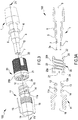
- the connection system 100 comprises a first connector 1, shown in the exploded view of figure 3 and in the respective cross section in figure 3A , comprising a main body having tubular shape and defining an internal channel 7 for fluid passage: the main body of the first connector 1 and the internal channel 7 preferably extend in length along the same fluid flow axis, between a connection port 9 configured to be fixed/connected in a fluid tight manner to a fluid line 51 or directly to the medical machine 200 (or an accessory), and a coupling portion 2.
- the connection port 9 may be a male or female connection port.
- a tube end portion is irremovably fixed inside the connection port via e.g., gluing or bonding.
- the coupling portion 2 of the first connector 1 has preferably tubular shape and includes a tip portion 2a surrounding the internal channel: the coupling portion 2 has a tapered external surface, so that a diameter of the coupling portion 2 reduces towards the tip portion 2a of the coupling portion 2.
- the tapered external surface of the tip portion 2a of the coupling portion 2 has a taper angle comprised between 1° and 6°, more in particular comprised between 3° and 4°, more in detail the taper angle is equal to 3.44°.
- the first connector 1, and in particular the coupling portion 2 of the first connector 1 is a Luer type connector: this means that dimensions of the coupling portion 2, the diameter of the internal channel 7 and the overall length of the first connector 1 are consistent with the Luer standards.
- the first connector 1 has a length comprised between 2 cm and 4 cm, and the internal channel 7 has an average diameter comprises between 2 mm and 3 mm.
- the first connector 1 further comprises a main abutment portion 5 arranged on an external lateral wall of the main body, wherein the main abutment portion 5 defines a protrusion radially extending outward from the main body.
- the abutment portion 5 may have circular shape, for example a ring coupled to the main body extending outwardly.
- the first connector 1 may further comprise an auxiliary abutment portion 6 arranged on the external lateral wall of the main body, wherein the auxiliary abutment portion 6 is axially distal from the main abutment portion 5 by an axial gap, so that a recess 8 is defined between the main abutment portion 5 and the auxiliary abutment portion 6.
- the auxiliary abutment portion 6 is axially interposed between the connection port 9 and the main abutment portion 5: similarly, the main abutment portion 5 is interposed between the coupling portion 2 and the auxiliary abutment portion 6.
- the first connector 1 is a male connector and it is made in one single piece preferably in plastic material, such as PVC, MBS, PC, or in metallic material, such as stainless steel.
- connection system 100 further comprises a second connector 11, shown in the exploded view of figure 3 or in the cross section view of figure 3A , presenting a main body having tubular shape and defining an internal channel 17 for fluid passage: the main body of the second connector 11 and the internal channel 17 preferably extend in length, along the same fluid flow axis, between a connection port 19 configured to be fixed/connected in a fluid tight manner to a fluid line 51 or directly to the medical machine 200 (or an accessory), and a coupling portion 12.
- the connection port 19 may be a male or female connection port.
- a tube end portion is irremovably fixed inside the connection port 19 via e.g., gluing or bonding.
- the coupling portion 12 of the second connector 11 is configured to be connected to the coupling portion 2 of the first connector 1 in a fluid tight manner, so that a fluid is able to flow between the first and the second connectors 1, 11, and vice versa, in particular wherein the fluid is able to flow between the connection port 9 of the first connector 1 and the connection port 19 of the second connector 11, and vice versa.
- the coupling portion 2 of the first connector 1 is connected to the coupling portion 12 of the second connector 11
- the fluid flow axis of the first connector 1 coincides with the fluid flow axis of the second connector 11
- the internal channels 7, 17 respectively of the first and the second connectors 1, 11 define a unique internal channel for fluid passage extending from the connection port 9 of the first connector 1 to the connection port 19 of the second connector 11.
- the coupling portion 12 of the second connector 11 has preferably tubular shape and includes a terminal portion 12a surrounding the internal channel 17 and having a tapered internal surface, so that a diameter of the tapered internal surface increases towards the terminal portion 12a.
- the tapered internal surface of the terminal portion 12a of the second connector 11 is counter shaped to the tapered external surface of the tip portion 2a of the first connector 1.
- both the coupling portion 2 of the first connector 1 and the coupling portion 12 of the second connector 11 have conical shape.
- the tip portion 2a of the first connector 1 is configured to enter into and to contact the terminal portion 12a of the second connector 11, to define a fluid tight connection: the tapered external surface is configured to couple with the tapered internal surface to connect the first and the second connectors 1, 11 in a fluid tight manner.
- the tapered internal surface of the terminal portion 12a of the coupling portion 2 has a taper angle comprised between 1° and 6°, more in particular comprised between 3° and 4°, more in detail the taper angle is equal to 3.44°.
- the taper angle of the coupling portion 2 of the first connector 1 is equal to the taper angle of the coupling portion 12 of the second connector 11.
- the second connector 11, and in particular the coupling portion 12 of the second connector 11, is a Luer type connector: this means that dimensions of the coupling portion 12, the diameter of the internal channel 17 and the overall length of the second connector 11 are consistent with the Luer standards.
- the second connector 11 has a length comprised between 2 cm and 3 cm, and the internal channel 17 has an average diameter comprises between 3 mm and 4 mm.
- the second connector 11 further comprises a hooking portion 13 arranged on an external lateral wall 11a of the main body of the second connector 11: in particular the hooking portion 13 may comprise a thread, preferably arranged in the proximity of the coupling portion 12 of the second connector 11.
- the threads of the hooking portion 13 preferably extend from the terminal end 12a of the second connector 11 and preferably emerge from the external lateral wall 11a of the main body of the second connector 11.
- the hooking portion 13 of the second connector 11 may comprise a respective undercut joint (embodiment not shown in the attached figures).
- the second connector 11 further comprises at least one locking projection 14 arranged on the same external lateral wall 11a of the main body of the second connector 11.
- the at least one locking projection 14 is interposed between the hooking portion 13 and the connection port 19: similarly, the hooking portion 13 is interposed between the at least one locking projection 14 and the terminal end 12a of the second connector 11.
- the at least one locking projection 14 radially emerges outwardly from the main body of the second connector 11: in particular the at least one locking projection 14 comprises a plurality of socket teeth, wherein the socket teeth are wedge-shaped or have a saw tooth shape.
- the socket teeth are preferably arranged all around the tubular main body of the second connector 11, as shown in figure 3 .
- the second connector 11 is a female connector and it is made in one single piece preferably in plastic material, such as PVC, MBS, PC or in metallic material, such as stainless steel.
- the second connector 11 may also comprise gripping means arranged on the external lateral wall 11a at the connection port 19: the gripping means are configured to allow an operator to grab firmly the second connector 11 especially when connection with the first connector 1 is required.
- the gripping means 15 preferably comprise tabs, in particular two tabs diametrically opposed, emerging radially outwardly from the main body of the second connector 11.
- the connection system 100 further comprises a collar 20, shown in the exploded view of figure 3 and in the cross section view of figure 3A , presenting a main body having tubular shape: in particular the collar extends in length between a first opening 21 and a second opening 22, and the tubular main body comprises an external lateral wall20b and an internal lateral wall 20a.
- the main body of the collar 20 may have polygonal shape, such as squared, rectangular or a combination of polygonal and tubular shapes.
- the collar 20 comprises an internal channel laterally limited by the first and the second openings 21, 22, wherein the opening 21 is configured to receive through insertion the second connector 11, in particular to receive the coupling portion 12, the hooking portion 13 and the at least one locking projection 14 of the second connector 11, while the second opening 22 allows the collar 20 to be mounted over, and coupled to, the first connector 1, as shown in figure 7.
- the second opening 22 receives in insertion the first connector 1, so that the collar surrounds externally at least part of the first connector 1 and the main body of the collar 20 is coaxial with the first connector 1.
- the collar 20 comprises, preferably at the second opening 22, a respective abutment portion 25 configured to contact the main abutment portion 5 of the first connector 1 when disposed in an abutment configuration, so that the collar 20 is axially constrained with respect to the first connector 1 at least along one axial direction.
- the collar 20 is axially constrained towards the coupling portion 2 of the first connector 1, so that the collar 20 is prevented to axially move towards the coupling portion 2 of the first connector 1 beyond a certain limit.
- the abutment portion 25 of the collar 20, as shown in the section of figure 6 is arranged at the second opening 22 of the collar 20 and extends radially inwardly.
- the first connector comprises both the main and the auxiliary abutment portions 5, 6, so that the abutment portion 25 of the collar is interposed between the main abutment portion 5 and the auxiliary abutment portion 6 of the first connector: therefore, the collar is a axially constrained to the first connector 1 through the main and auxiliary abutment portions 5, 6 of the first connector 1, so that an axial movement of the collar 20 with respect to the first connector 1 is substantially prevented.
- the collar 20 may be axially movable with respect to the first connector 1 within the axial gap defined between said main and auxiliary abutment portions 5, 6 of the first connector 1, and axially constrained to the first connector 1 out of this axial gap.
- the collar 20 is axially movable with respect to the first connector 1 of an amount proportional to the distance between the main and the auxiliary abutment portions 5, 6 of the first connector 1.
- the axial movement is defined along the fluid flow axis of the first connector 1 and/or of the second connector 11.
- the first connector comprises the main and the auxiliary abutment portions 5, 6, the abutment portion 25 of the collar 20 is arranged at, and in particular surrounds, the recess 8 of the first connector 1.
- the second opening 22 has an internal diameter lower than an external diameter of the main abutment portion 5 of the first connector 1, preventing in this way the axial movement.
- first connector 1 and the collar although they are distinct bodies both made in a single piece, are axially coupled each other, being the collar 20 movable by rotation with respect to the first connector 1.
- the collar 20 has a length, measured along an axis of its tubular main body, comprised between 8 mm and 25 mm, and a diameter comprised between 7 mm and 15 mm
- the collar 20 further comprises a respective hooking portion 23 configured to be engaged with the hooking portion 13 of the second connector 11 through an engagement rotation ER along an engagement direction (see figure 2 ) defining an engaged configuration shown in figures 1 and 2 , so that when the connection system 100 is disposed in this engaged configuration the hooking portion 23 of the collar 20 and the hooking portion 13 of the second connector 11 prevent axial removal of the collar 20 from the second connector 11.
- the hooking portion 23 of the collar comprises a thread configured to engage the thread of the second connector 11 through this engagement rotation.
- the hooking portion 23 is arranged on the internal lateral wall 20a of the collar 20. In other words, in this engaged configuration, the collar 20 is screwed over the second connector 11 through the respective threads, defining an axial constraint between the collar 20 and the second connector 11.
- the hooking portion 23 of the collar 20 comprises an undercut joint (not shown in the attached figures) and the hooking portion 13 of the second connector 11 comprises the respective undercut joint, wherein the undercut joint of the collar 20 is configured to axially engage the undercut joint of the second connector 11 defining a bayonet coupling for example through the same engagement rotation ER, so that an axial movement, in particular an axial separation, of the first and second connectors 1, 11 is prevented: this axial movement or axial separation is considered along the fluid flow axis of the first or second connectors 1, 11.
- the engagement rotation is comprised between 10° and 180°, in particular comprised between 15° and 95°.
- the collar 20 is axially coupled to the first connector 1, when the connection system 100 is disposed in this engaged configuration the first connector 1 is axially coupled to the second connector 11, so that disconnection of the first and second connectors 1, 11 is prevented.
- the hooking portions 13, 23 respectively of the second connector 11 and of the collar 20 contribute to tighten the connection and to prevent disconnection between the coupling portion 2 of the first connector 1 and the coupling portion 12 of the second connector 11.
- the coupling portion 2 of the first connector 1 is allowed to stay aligned with the coupling portion 12 of the second connector 11 due to the fact that the collar 20 is freely movable by rotation with respect to the first connector 1: once the connection between the coupling portion 2 of the first connector 1 and the coupling portion 12 of the second connector 11 is established, the collar 20 is still freely movable by rotation with respect to the first and second connectors 1, 11, so that the subsequent engagement rotation ER does not determined friction between the coupling portion 2 of the first connector 1 and the coupling portion 12 of the second connector 11.
- the first and the second connectors 1, 11 may be aligned each other without reciprocal rotation, while the collar 20 rotates with respect both the first and second connectors 1, 11 to determine engagement of the hooking portions 13, 23.
- the collar 20 further comprises a respective at least one locking projection 24 engageable to the at least one locking projection 14 of the second connector 11 through the engagement rotation ER of the collar 20 with respect to the second connector 11 along the engagement direction.
- the connection system 100 may be disposed in a coupled configuration, wherein the at least one locking projection 24 of the collar 20 cooperates with the at least one locking projection 14 of the second connector 11, preventing a disengagement rotation of the collar 20 with respect to the second connector 11: this disengagement rotation is a rotation in a opposite direction with respect to the engagement rotation.
- the coupled configuration is defined at least at an end stage of the engagement rotation between the collar 20 and the second connector 11, meaning that when the engagement rotation is complete, a disengagement rotation of the collar 20 with respect to the first connector 1 is prevented.
- the coupled configuration may be defined at an intermediate or initial stage of the engagement rotation ER: this means that, as soon as the hooking portion 23 of the collar 20 engages the hooking portion 13 of the second connector 11, the locking projections 14, 24, respectively of the second connector 11 and of the collar 20, also cooperate each other, preventing the disengagement rotation.
- this locking projections 24 are arranged on the internal lateral wall 20a of the collar, so that the locking projection 24 and the hooking portion 23 of the collar 20 are arranged side by side.
- the at least one locking projection 24 of the collar may comprise a plurality of socket teeth, wherein the socket teeth are wedge-shaped or have a saw tooth shape.
- the at least one locking projection 14 radially emerges inwardly from the internal lateral wall 20a of the collar, as shown in figure 3 .
- the socket teeth of both the second connector 11 and the collar 20 are arranged circumferentially all around the external lateral wall 11a of the second connector 11 and circumferentially all around the internal lateral wall 20a of the collar 20.
- the socket teeth radially define recesses and protrusions alternately, so that the second connector 11 defines a maximum external diameter of encumbrance measured at the protrusions of the socket teeth, and wherein the collar 20 defines a minimum internal diameter measured at the protrusions of the socket teeth of the collar 20: this maximum external diameter of encumbrance is higher than this minimum internal diameter so that, when the socket teeth of the second connector 11 are faced to or in contact with the socket teeth of the collar 20, the protrusions of the socket teeth of the second connector 11 are placed into the recesses of the socket teeth of the collar 20 and vice versa.
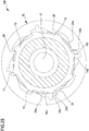
- This is clearly shown in the cross section view of figure 2B , wherein the saw tooth shape of the locking projections allows the engagement rotation and prevents the disengagement rotation.
- the socket teeth of the second connector 11 and of the collar 20 comprise each a respective slide surface 14a, 24a ( figure 2B ) tilted with respect to the external surface of the second connector 11 and to the internal lateral wall 20a of the collar 20: preferably this slide surface 24a is tilted by an angle lower than 60°.
- Each of the socket teeth of the second connector 11 and of the collar 20 further comprise respective lock surfaces 14b, 24b which are substantially perpendicular with respect to the external surface of the second connector 11 and to the internal lateral wall 20a of the collar 20: the slide surface 14a, 24a and the lock surface 14b, 24b of each socket tooth are connected together at a vertex defining the protrusion.
- the slide surface 14a, 24a and the lock surface 14b, 24b, of one socket tooth define a triangle shaped tooth, wherein these teeth are radially arranged over the internal lateral wall 20a of the collar 20 and over the external lateral wall 11a of the second connector 11.
- the socket teeth of the collar 20 are oriented in an opposite direction with respect to the socket teeth of the second connector 11, so that the lock surfaces 14b of the socket teeth of the second connector 11 may be faced to the lock surfaces 24b of the collar 20.
- Each slide surface 14a of a socket tooth of the second connector 11 is configured to cooperate or contact with a respective slide surface 24a of a socket tooth of the collar 20, so that the engagement rotation is allowed: on the other hand, each lock surface 14b of a socket tooth of the second connector 11 is configured to contact, when the connection system 100 is disposed in the coupled configuration, with a respective lock surface 24b of a socket tooth of the collar 20, preventing therefore the disengagement rotation: in particular, when the connection system 100 is disposed in the coupled configuration, each lock surface 14b of a socket tooth of the second connector 11 abuts against a respective lock surface 24b of a socket tooth of the collar 20.
- the hooking portion 13 of the second connector 11 is interposed between the at least one locking projection 14 and the terminal portion 12a of the coupling portion 12, and the at least one locking projection 24 of the collar 20 is arranged at an inlet of the first opening 21 so that the hooking portion 23 of the collar
- the at least one locking projection 14 of the second connector 11 is interposed between the hooking portion 13 and the terminal portion 12a of the coupling portion 12, and the hooking portion 23 of the collar 20 is arranged at the inlet of the first opening 21 so that the at least one locking projection 24 of the collar 20 is interposed between the hooking portion 23 and the second opening 22 of the collar 20.
- the connection system 100 is configurable in an unlocked condition, wherein the collar 20 is movable by rotation with respect to the first connector 1 and the at least one locking projection 24 of the collar 20 and the at least one locking projection 14 of the second connector 11 are in an uncoupled configuration wherein the locking projections do not cooperate each other.
- the unlocked condition is shown in figure 4 , wherein the first and the second connectors 1, 11 are separated: when the first and the second connectors 1, 11 are separated, the collar 20 is anyhow axially constrained to the first connector through the main and auxiliary abutment portions 5, 6 of the first connector 1 cooperating with the abutment portion 25 of the collar.
- the unlocked condition may also be defined when the hooking portion 13 of the second connector 11 is engaged with the hooking portion 23 of the collar 20, which defines the engaged configuration: this means that, when an engagement rotation is at an initial or intermediate stage, the at least one locking projection 24 of the collar 20 and the at least one locking projection 14 of the second connector 11 do not cooperate yet, allowing disengagement rotation of the collar 20 with respect to the first connector 1.
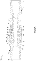
- connection system 100 is further configurable in a locked condition, shown in figures 1, 2 , and in the section view of figure 2A , wherein the at least one locking projection 24 of the collar 20 and the at least one locking projection 14 of the second connector 11 are in the coupled configuration, and the hooking portion 23 of the collar 20 and the hooking portion 13 of the second connector 11 are in the engaged configuration.
- the collar 20 is irremovably engaged to the second connector 11 through said engagement rotation: in particular, the at least one locking projection 14 and the hooking portion 13 of the second connector 11 respectively cooperate with the at least one locking projection 24 and the hooking portion 23 of the collar 20 preventing disengagement of the first connector 1 from the second connector 11.
- connection system 100 when the connection system 100 is disposed in the locked condition, the coupling portion 2 of the first connector 1 is connected to and/or inserted into the coupling portion 12 of the second connector 11, so that fluid tightness between the first and the second connector 1, 11 is established. Moreover, in this locked condition, the abutment portion 25 of the collar 20 abuts against the main abutment portion 5 of the first connector 1, preventing the axial movement, and therefore separation, of the first connector with respect to the collar.
- the locking portions 14 and 24 respectively of the second connector 11 and of the collar 20 should have a width, measured parallel to the fluid flow axis, higher than this gap, in order to prevent decoupling.
- the fluid flow axis of the first connector 1 coincides with the fluid flow axis of the second connector 11, and the collar is coaxial with this fluid flow axis.
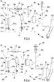
- the invention also refers to a disposable set 50, shown in figures 5 and 6 , for a blood treatment apparatus 200, such as a dialysis machine.
- the disposable set 50 comprises a plurality of fluid lines 51, such as a blood circuit 50a which includes an access line 52 configured to be connected to a patient 300 and to an inlet port 201a of a blood treatment unit 201, such as a hemofilter, an ultrafilter, a hemodiafilter, a dialyzer, a plasmafilter and the like.
- the blood circuit 50a also comprises a return line 53 configured to be connected to the patient 300 and to an outlet port 201b of the same blood treatment unit 201. In this configuration, blood is supposed to flow from the patient along the access line 52, through the blood treatment unit 201, and towards the return line 53, as shown by the arrows depicted on the fluid lines of figures 5 and 6 .
- the disposable set 50 may also comprise one or more infusion lines 54 connected to the blood circuit 52 and/or configured to be connected to the patient 300.
- the infusion line 54 may comprise a container 60 connected to one end of the infusion line and wherein the other end of the infusion line 54 is connected to the blood circuit or to the patient.
- This container 60 is configured for housing an infusion fluid and is made, for example, of plastic material for medical applications: in particular the container 60 may be a citrate solution container 60a containing a citrate concentrated solution, or calcium solution container 60b containing a calcium concentrated solution, or a substitute fluid solution to be injected into the blood circuit during treatment.
- FIG. 5 and 6 shows a (pre-) infusion line 54 arranged upstream with respect to the blood treatment unit 201 and connected to a citrate solution container 60a.
- the infusion line 54 is also placed upstream a blood pump 91 to provide regional anticoagulation to the extracorporeal blood.
- At least one pump 90 may be associated to the infusion line 54 and configured to determine fluid flow from the container 60 towards the other end of the infusion line 54, for example towards the access line 52 or to the return line 53.
- the pumps 90 and 91 are peristaltic pumps.
- infusion lines may be included in the circuit and are not represented.
- a pre-infusion line injecting substitution fluid upstream the blood treatment unit 201 and downstream the blood pump 91 may be included, as well as a post-infusion line injecting a substitute solution into the return line 53, for example into the venous bubble trap (not shown).
- Figures 5 and 6 also show an additional infusion line 54 arranged downstream with respect to the to the blood treatment unit 201 and connected to the calcium solution container 60a, for example a syringe configured for housing a calcium solution.
- This infusion line is intended to reestablish the ion balance in a regional anticoagulation procedure.
- the blood pump 91 is associated to the access line 52 and/or to the return line 53 to determine blood flow through the treatment unit 201.
- the disposable set 50 may also comprise a monitoring line 55, not shown in the attached figures, connected to the blood circuit 50a or to any of the infusion lines 54, and configured e.g., to be connected to a pressure or to temperature gauge for parameter detection or to be used as a site access for blood sampling.
- a monitoring line 55 not shown in the attached figures, connected to the blood circuit 50a or to any of the infusion lines 54, and configured e.g., to be connected to a pressure or to temperature gauge for parameter detection or to be used as a site access for blood sampling.
- the disposable set 50 may also comprise a warmer accessory 70, such as a bag or a line and schematically shown in figures 5 and 6 , connected to the blood circuit 50a (e.g. downstream the treatment unit 201) and configured to warm up the blood before return to the patient 300.
- a warmer accessory 70 is connected in series to the return line 53, so that an inlet 70a of the warmer accessory 70 is connected to an upstream tract of the return line 53, and an outlet 70b of the warmer accessory 70 is connected to a downstream tract of the return line 53.
- the disposable set 50 further comprises at least one connection system 100 as previously described, which may be connected to the access line 52, the return line 53, to the infusion line 54 and the monitoring line 55.
- the connection system 100 connects the (calcium) infusion line 54 to the blood circuit; alternatively or in addition the connection system may be used to connect the citrate solution container 60a to the pre blood pump infusion line 54.
- the connections system 100 may connect the inlet 70a and the outlet 70b of the warmer accessory 70 to the return line 53, in order to prevent any undesired disconnection.
- the disposable set 50 also comprises the blood treatment unit 201 having a blood inlet 201a connected to the access line 52, a blood outlet 201b connected to the return line 53, a fluid inlet 201c connected to a fluid delivery line 210 configured to be connected to a source of fresh treatment fluid (not shown in the attached figures), and a fluid outlet 201d connected to a fluid output line 211 configured to be attached to an exhaust unit, such as a discharge bag.
- the blood treatment unit 201 having a blood inlet 201a connected to the access line 52, a blood outlet 201b connected to the return line 53, a fluid inlet 201c connected to a fluid delivery line 210 configured to be connected to a source of fresh treatment fluid (not shown in the attached figures), and a fluid outlet 201d connected to a fluid output line 211 configured to be attached to an exhaust unit, such as a discharge bag.
- connection system 100 may also be used to connected the blood inlet 201a of the blood treatment unit 201 to the access line 52, the blood outlet 201b to the return line 53, the fluid inlet 201c to the fluid delivery line 210 and the fluid outlet 201d to the fluid output line 211 (if proper or necessary).
- the disposable set 50 may also comprise a disposable accessory 80, such as a gas exchanger, an oxygenator or an auxiliary fluid arrangement, connected to the blood line 50a, in particular a gas exchanger 80 may be connected in series to the return line 53.
- the gas exchanger 80 is configured to remove CO 2 from the blood before returning it to the patient 300.
- the gas exchanger comprises a blood inlet 80a and a blood outlet 80b for connection to the return line 53: the connection system 100, in an embodiment not shown in the attached figures, may further be used for connecting the blood inlet 80a of the gas exchanger 80 to an upstream tract of the return line 53, and the blood outlet 80b to a downstream tract of the return line 53.
- the disposable set may also comprise an add-on accessory 81 connected to the blood circuit 50a through the connection system 100 as shown in figure 6 .
- the add-on accessory 81 is interposed between the patient (in particular the patient vascular access) and the access and return lines of the blood circuit; the add-on accessory 81 comprises an arterial blood inlet 81a configured to be connected to an arterial access of the patient 300, an arterial blood outlet 81b connected to the access line 52 of the disposable set 50, a venous blood inlet 81c connected to the return line 53 of the disposable set 50, and a venous blood outlet 81d configured to be connected to a venous access of the patient 300.
- the connection system may be interposed in connection between the arterial blood outlet 81b and the access line 52, and between the venous blood inlet 81c and the return line 53.
- the disposable set may include several additional elements not represented/described since well-known to the skilled person, such as deaeration chambers, pressure monitoring components, infusion or sampling sites, bubble detectors, venous and arterial clamps to stop blood circulation, etc.
- the disposable set may be a set for acute or chronic treatments and may assume different configurations with respect to the shown exemplary set.
Landscapes
- Health & Medical Sciences (AREA)
- Heart & Thoracic Surgery (AREA)
- Engineering & Computer Science (AREA)
- Public Health (AREA)
- Veterinary Medicine (AREA)
- Anesthesiology (AREA)
- Biomedical Technology (AREA)
- Hematology (AREA)
- Life Sciences & Earth Sciences (AREA)
- Animal Behavior & Ethology (AREA)
- General Health & Medical Sciences (AREA)
- Cardiology (AREA)
- Pulmonology (AREA)
- Mechanical Engineering (AREA)
- Vascular Medicine (AREA)
- General Engineering & Computer Science (AREA)
- Urology & Nephrology (AREA)
- Epidemiology (AREA)
- Emergency Medicine (AREA)
- Infusion, Injection, And Reservoir Apparatuses (AREA)
Priority Applications (6)
| Application Number | Priority Date | Filing Date | Title |
|---|---|---|---|
| EP19191551.1A EP3777936B1 (de) | 2019-08-13 | 2019-08-13 | Nicht abnehmbares verbindungssystem |
| CN202510233046.6A CN120053871A (zh) | 2019-08-13 | 2020-08-11 | 不能移除的连接系统 |
| CN202080071804.4A CN114555174A (zh) | 2019-08-13 | 2020-08-11 | 不能移除的连接系统 |
| US17/634,855 US20220296870A1 (en) | 2019-08-13 | 2020-08-11 | Non-removable connection system |
| PCT/EP2020/072498 WO2021028434A1 (en) | 2019-08-13 | 2020-08-11 | Non-removable connection system |
| EP20751176.7A EP4013477A1 (de) | 2019-08-13 | 2020-08-11 | Nicht abnehmbares verbindungssystem |
Applications Claiming Priority (1)
| Application Number | Priority Date | Filing Date | Title |
|---|---|---|---|
| EP19191551.1A EP3777936B1 (de) | 2019-08-13 | 2019-08-13 | Nicht abnehmbares verbindungssystem |
Publications (2)
| Publication Number | Publication Date |
|---|---|
| EP3777936A1 true EP3777936A1 (de) | 2021-02-17 |
| EP3777936B1 EP3777936B1 (de) | 2021-09-22 |
Family
ID=67620356
Family Applications (2)
| Application Number | Title | Priority Date | Filing Date |
|---|---|---|---|
| EP19191551.1A Active EP3777936B1 (de) | 2019-08-13 | 2019-08-13 | Nicht abnehmbares verbindungssystem |
| EP20751176.7A Pending EP4013477A1 (de) | 2019-08-13 | 2020-08-11 | Nicht abnehmbares verbindungssystem |
Family Applications After (1)
| Application Number | Title | Priority Date | Filing Date |
|---|---|---|---|
| EP20751176.7A Pending EP4013477A1 (de) | 2019-08-13 | 2020-08-11 | Nicht abnehmbares verbindungssystem |
Country Status (4)
| Country | Link |
|---|---|
| US (1) | US20220296870A1 (de) |
| EP (2) | EP3777936B1 (de) |
| CN (2) | CN120053871A (de) |
| WO (1) | WO2021028434A1 (de) |
Families Citing this family (2)
| Publication number | Priority date | Publication date | Assignee | Title |
|---|---|---|---|---|
| US20210178143A1 (en) * | 2019-12-16 | 2021-06-17 | Codan Holding Gmbh | Nondisconnectable, securable connector having a capping sleeve |
| US20250360300A1 (en) * | 2024-05-22 | 2025-11-27 | Becton Dickinson And Company | Non-Disconnectable Luer Lock |
Citations (5)
| Publication number | Priority date | Publication date | Assignee | Title |
|---|---|---|---|---|
| GB2451891A (en) * | 2007-08-17 | 2009-02-18 | Univ Sheffield Hallam | Medical fluid connector with features to ensure correct coupling |
| EP2620178A1 (de) * | 2012-01-24 | 2013-07-31 | Industrie Borla SpA | Konnektor für medizinische Linien |
| US20140243797A1 (en) * | 2013-02-27 | 2014-08-28 | Fresenius Medical Care Holdings, Inc. | Fluid line connectors |
| US8882726B2 (en) | 2010-03-10 | 2014-11-11 | Becton Dickinson France | Drug delivery device with safe connection means |
| WO2016012834A1 (en) * | 2014-07-21 | 2016-01-28 | Industrie Borla S.P.A. | Safety cap for medical devices |
Family Cites Families (14)
| Publication number | Priority date | Publication date | Assignee | Title |
|---|---|---|---|---|
| US4211439A (en) * | 1978-07-26 | 1980-07-08 | Moldestad Jon P | Safety device for hose connections |
| JPS58165865A (ja) * | 1982-03-26 | 1983-09-30 | 川澄化学工業株式会社 | 体液処理装置 |
| US4452473A (en) * | 1982-07-26 | 1984-06-05 | Baxter Travenol Laboratories, Inc. | Luer connection system |
| CA2235601A1 (en) * | 1995-10-26 | 1997-05-01 | Medisystems Technology Corporation | Pressure measurement in blood treatment |
| US6402207B1 (en) * | 1997-06-09 | 2002-06-11 | Qd Enterprises, Llc | Safety indexed medical connectors |
| JP3907866B2 (ja) * | 1999-05-19 | 2007-04-18 | 有限会社 北九州生命情報科学院 | 自動血液透析装置 |
| JP3069839U (ja) * | 1999-12-21 | 2000-07-04 | 川澄化学工業株式会社 | 体外循環回路 |
| JP2008005974A (ja) * | 2006-06-28 | 2008-01-17 | Nippon Sherwood Medical Industries Ltd | ルアー固定フィッティング接続構造 |
| US8777931B2 (en) * | 2011-08-19 | 2014-07-15 | Alcon Research, Ltd. | Retractable luer lock fittings |
| ITPI20110130A1 (it) * | 2011-11-21 | 2013-05-22 | Microtech S R L | Struttura di connettore per una linea medicale |
| FR2996141B1 (fr) * | 2012-09-28 | 2023-04-07 | Vygon | Systeme de connexion medicale anti-devissage |
| CN203215125U (zh) * | 2013-03-01 | 2013-09-25 | 中国航空工业集团公司沈阳发动机设计研究所 | 一种可自锁的螺纹连接管接头 |
| US10183158B2 (en) * | 2015-04-02 | 2019-01-22 | Koyo Sangyo Co., Ltd. | Connecting structure for medical use |
| US20220288378A1 (en) * | 2019-09-03 | 2022-09-15 | Elcam Medical A.C.A.L. | Breakaway intra-medical tubing connector assembly |
-
2019
- 2019-08-13 EP EP19191551.1A patent/EP3777936B1/de active Active
-
2020
- 2020-08-11 WO PCT/EP2020/072498 patent/WO2021028434A1/en not_active Ceased
- 2020-08-11 CN CN202510233046.6A patent/CN120053871A/zh active Pending
- 2020-08-11 CN CN202080071804.4A patent/CN114555174A/zh active Pending
- 2020-08-11 US US17/634,855 patent/US20220296870A1/en active Pending
- 2020-08-11 EP EP20751176.7A patent/EP4013477A1/de active Pending
Patent Citations (5)
| Publication number | Priority date | Publication date | Assignee | Title |
|---|---|---|---|---|
| GB2451891A (en) * | 2007-08-17 | 2009-02-18 | Univ Sheffield Hallam | Medical fluid connector with features to ensure correct coupling |
| US8882726B2 (en) | 2010-03-10 | 2014-11-11 | Becton Dickinson France | Drug delivery device with safe connection means |
| EP2620178A1 (de) * | 2012-01-24 | 2013-07-31 | Industrie Borla SpA | Konnektor für medizinische Linien |
| US20140243797A1 (en) * | 2013-02-27 | 2014-08-28 | Fresenius Medical Care Holdings, Inc. | Fluid line connectors |
| WO2016012834A1 (en) * | 2014-07-21 | 2016-01-28 | Industrie Borla S.P.A. | Safety cap for medical devices |
Also Published As
| Publication number | Publication date |
|---|---|
| EP4013477A1 (de) | 2022-06-22 |
| WO2021028434A1 (en) | 2021-02-18 |
| CN120053871A (zh) | 2025-05-30 |
| CN114555174A (zh) | 2022-05-27 |
| US20220296870A1 (en) | 2022-09-22 |
| EP3777936B1 (de) | 2021-09-22 |
Similar Documents
| Publication | Publication Date | Title |
|---|---|---|
| EP1280579B1 (de) | Multiluminales intravenöses verländerungsstück | |
| JP6706675B2 (ja) | 医療用チューブのためのフレア状ルアーコネクタのためのシステム及び方法 | |
| RU2444383C2 (ru) | Система для установления соединения по потоку | |
| AU2017339953B2 (en) | Syringe with enteral connection feature | |
| EP3976131B1 (de) | Quellbehälteranschluss | |
| WO2003090841A1 (en) | Tubing connector | |
| AU2021228640B2 (en) | Syringe with snap-in enteral connection feature | |
| CN102548521B (zh) | 具有用于药物输注的插入件的管道组件 | |
| US20220296870A1 (en) | Non-removable connection system | |
| CN107708789B (zh) | 凸式流体连接器、凹式流体连接器以及包括两者的流体连接系统 | |
| DK2872202T3 (en) | S P R E J T E / K A N A L K O M B I N A T I O N M E D L A V R E S T V O L U M E N O G S P R O J T E T I L S A D A N SPRAY / CHANNEL COMBINATE | |
| US20220355066A1 (en) | Dual-Lumen Catheter Assembly | |
| US20210220538A1 (en) | Arterial chambers for hemodialysis and related systems and tubing sets |
Legal Events
| Date | Code | Title | Description |
|---|---|---|---|
| PUAI | Public reference made under article 153(3) epc to a published international application that has entered the european phase |
Free format text: ORIGINAL CODE: 0009012 |
|
| STAA | Information on the status of an ep patent application or granted ep patent |
Free format text: STATUS: THE APPLICATION HAS BEEN PUBLISHED |
|
| AK | Designated contracting states |
Kind code of ref document: A1 Designated state(s): AL AT BE BG CH CY CZ DE DK EE ES FI FR GB GR HR HU IE IS IT LI LT LU LV MC MK MT NL NO PL PT RO RS SE SI SK SM TR |
|
| AX | Request for extension of the european patent |
Extension state: BA ME |
|
| STAA | Information on the status of an ep patent application or granted ep patent |
Free format text: STATUS: REQUEST FOR EXAMINATION WAS MADE |
|
| 17P | Request for examination filed |
Effective date: 20210219 |
|
| RBV | Designated contracting states (corrected) |
Designated state(s): AL AT BE BG CH CY CZ DE DK EE ES FI FR GB GR HR HU IE IS IT LI LT LU LV MC MK MT NL NO PL PT RO RS SE SI SK SM TR |
|
| GRAP | Despatch of communication of intention to grant a patent |
Free format text: ORIGINAL CODE: EPIDOSNIGR1 |
|
| STAA | Information on the status of an ep patent application or granted ep patent |
Free format text: STATUS: GRANT OF PATENT IS INTENDED |
|
| INTG | Intention to grant announced |
Effective date: 20210421 |
|
| GRAS | Grant fee paid |
Free format text: ORIGINAL CODE: EPIDOSNIGR3 |
|
| GRAA | (expected) grant |
Free format text: ORIGINAL CODE: 0009210 |
|
| STAA | Information on the status of an ep patent application or granted ep patent |
Free format text: STATUS: THE PATENT HAS BEEN GRANTED |
|
| AK | Designated contracting states |
Kind code of ref document: B1 Designated state(s): AL AT BE BG CH CY CZ DE DK EE ES FI FR GB GR HR HU IE IS IT LI LT LU LV MC MK MT NL NO PL PT RO RS SE SI SK SM TR |
|
| REG | Reference to a national code |
Ref country code: GB Ref legal event code: FG4D |
|
| REG | Reference to a national code |
Ref country code: IE Ref legal event code: FG4D |
|
| REG | Reference to a national code |
Ref country code: DE Ref legal event code: R096 Ref document number: 602019007815 Country of ref document: DE |
|
| REG | Reference to a national code |
Ref country code: CH Ref legal event code: EP Ref country code: AT Ref legal event code: REF Ref document number: 1431819 Country of ref document: AT Kind code of ref document: T Effective date: 20211015 |
|
| REG | Reference to a national code |
Ref country code: LT Ref legal event code: MG9D |
|
| REG | Reference to a national code |
Ref country code: NL Ref legal event code: MP Effective date: 20210922 |
|
| PG25 | Lapsed in a contracting state [announced via postgrant information from national office to epo] |
Ref country code: HR Free format text: LAPSE BECAUSE OF FAILURE TO SUBMIT A TRANSLATION OF THE DESCRIPTION OR TO PAY THE FEE WITHIN THE PRESCRIBED TIME-LIMIT Effective date: 20210922 Ref country code: NO Free format text: LAPSE BECAUSE OF FAILURE TO SUBMIT A TRANSLATION OF THE DESCRIPTION OR TO PAY THE FEE WITHIN THE PRESCRIBED TIME-LIMIT Effective date: 20211222 Ref country code: LT Free format text: LAPSE BECAUSE OF FAILURE TO SUBMIT A TRANSLATION OF THE DESCRIPTION OR TO PAY THE FEE WITHIN THE PRESCRIBED TIME-LIMIT Effective date: 20210922 Ref country code: BG Free format text: LAPSE BECAUSE OF FAILURE TO SUBMIT A TRANSLATION OF THE DESCRIPTION OR TO PAY THE FEE WITHIN THE PRESCRIBED TIME-LIMIT Effective date: 20211222 Ref country code: SE Free format text: LAPSE BECAUSE OF FAILURE TO SUBMIT A TRANSLATION OF THE DESCRIPTION OR TO PAY THE FEE WITHIN THE PRESCRIBED TIME-LIMIT Effective date: 20210922 Ref country code: RS Free format text: LAPSE BECAUSE OF FAILURE TO SUBMIT A TRANSLATION OF THE DESCRIPTION OR TO PAY THE FEE WITHIN THE PRESCRIBED TIME-LIMIT Effective date: 20210922 Ref country code: FI Free format text: LAPSE BECAUSE OF FAILURE TO SUBMIT A TRANSLATION OF THE DESCRIPTION OR TO PAY THE FEE WITHIN THE PRESCRIBED TIME-LIMIT Effective date: 20210922 |
|
| REG | Reference to a national code |
Ref country code: AT Ref legal event code: MK05 Ref document number: 1431819 Country of ref document: AT Kind code of ref document: T Effective date: 20210922 |
|
| PG25 | Lapsed in a contracting state [announced via postgrant information from national office to epo] |
Ref country code: LV Free format text: LAPSE BECAUSE OF FAILURE TO SUBMIT A TRANSLATION OF THE DESCRIPTION OR TO PAY THE FEE WITHIN THE PRESCRIBED TIME-LIMIT Effective date: 20210922 Ref country code: GR Free format text: LAPSE BECAUSE OF FAILURE TO SUBMIT A TRANSLATION OF THE DESCRIPTION OR TO PAY THE FEE WITHIN THE PRESCRIBED TIME-LIMIT Effective date: 20211223 |
|
| PG25 | Lapsed in a contracting state [announced via postgrant information from national office to epo] |
Ref country code: AT Free format text: LAPSE BECAUSE OF FAILURE TO SUBMIT A TRANSLATION OF THE DESCRIPTION OR TO PAY THE FEE WITHIN THE PRESCRIBED TIME-LIMIT Effective date: 20210922 |
|
| PG25 | Lapsed in a contracting state [announced via postgrant information from national office to epo] |
Ref country code: IS Free format text: LAPSE BECAUSE OF FAILURE TO SUBMIT A TRANSLATION OF THE DESCRIPTION OR TO PAY THE FEE WITHIN THE PRESCRIBED TIME-LIMIT Effective date: 20220122 Ref country code: SK Free format text: LAPSE BECAUSE OF FAILURE TO SUBMIT A TRANSLATION OF THE DESCRIPTION OR TO PAY THE FEE WITHIN THE PRESCRIBED TIME-LIMIT Effective date: 20210922 Ref country code: RO Free format text: LAPSE BECAUSE OF FAILURE TO SUBMIT A TRANSLATION OF THE DESCRIPTION OR TO PAY THE FEE WITHIN THE PRESCRIBED TIME-LIMIT Effective date: 20210922 Ref country code: PT Free format text: LAPSE BECAUSE OF FAILURE TO SUBMIT A TRANSLATION OF THE DESCRIPTION OR TO PAY THE FEE WITHIN THE PRESCRIBED TIME-LIMIT Effective date: 20220124 Ref country code: PL Free format text: LAPSE BECAUSE OF FAILURE TO SUBMIT A TRANSLATION OF THE DESCRIPTION OR TO PAY THE FEE WITHIN THE PRESCRIBED TIME-LIMIT Effective date: 20210922 Ref country code: NL Free format text: LAPSE BECAUSE OF FAILURE TO SUBMIT A TRANSLATION OF THE DESCRIPTION OR TO PAY THE FEE WITHIN THE PRESCRIBED TIME-LIMIT Effective date: 20210922 Ref country code: ES Free format text: LAPSE BECAUSE OF FAILURE TO SUBMIT A TRANSLATION OF THE DESCRIPTION OR TO PAY THE FEE WITHIN THE PRESCRIBED TIME-LIMIT Effective date: 20210922 Ref country code: EE Free format text: LAPSE BECAUSE OF FAILURE TO SUBMIT A TRANSLATION OF THE DESCRIPTION OR TO PAY THE FEE WITHIN THE PRESCRIBED TIME-LIMIT Effective date: 20210922 Ref country code: CZ Free format text: LAPSE BECAUSE OF FAILURE TO SUBMIT A TRANSLATION OF THE DESCRIPTION OR TO PAY THE FEE WITHIN THE PRESCRIBED TIME-LIMIT Effective date: 20210922 Ref country code: AL Free format text: LAPSE BECAUSE OF FAILURE TO SUBMIT A TRANSLATION OF THE DESCRIPTION OR TO PAY THE FEE WITHIN THE PRESCRIBED TIME-LIMIT Effective date: 20210922 |
|
| REG | Reference to a national code |
Ref country code: DE Ref legal event code: R097 Ref document number: 602019007815 Country of ref document: DE |
|
| PG25 | Lapsed in a contracting state [announced via postgrant information from national office to epo] |
Ref country code: DK Free format text: LAPSE BECAUSE OF FAILURE TO SUBMIT A TRANSLATION OF THE DESCRIPTION OR TO PAY THE FEE WITHIN THE PRESCRIBED TIME-LIMIT Effective date: 20210922 |
|
| PLBE | No opposition filed within time limit |
Free format text: ORIGINAL CODE: 0009261 |
|
| STAA | Information on the status of an ep patent application or granted ep patent |
Free format text: STATUS: NO OPPOSITION FILED WITHIN TIME LIMIT |
|
| 26N | No opposition filed |
Effective date: 20220623 |
|
| PG25 | Lapsed in a contracting state [announced via postgrant information from national office to epo] |
Ref country code: MC Free format text: LAPSE BECAUSE OF FAILURE TO SUBMIT A TRANSLATION OF THE DESCRIPTION OR TO PAY THE FEE WITHIN THE PRESCRIBED TIME-LIMIT Effective date: 20210922 |
|
| REG | Reference to a national code |
Ref country code: CH Ref legal event code: PL |
|
| PG25 | Lapsed in a contracting state [announced via postgrant information from national office to epo] |
Ref country code: LU Free format text: LAPSE BECAUSE OF NON-PAYMENT OF DUE FEES Effective date: 20220813 Ref country code: LI Free format text: LAPSE BECAUSE OF NON-PAYMENT OF DUE FEES Effective date: 20220831 Ref country code: CH Free format text: LAPSE BECAUSE OF NON-PAYMENT OF DUE FEES Effective date: 20220831 |
|
| REG | Reference to a national code |
Ref country code: BE Ref legal event code: MM Effective date: 20220831 |
|
| PG25 | Lapsed in a contracting state [announced via postgrant information from national office to epo] |
Ref country code: IE Free format text: LAPSE BECAUSE OF NON-PAYMENT OF DUE FEES Effective date: 20220813 |
|
| PG25 | Lapsed in a contracting state [announced via postgrant information from national office to epo] |
Ref country code: BE Free format text: LAPSE BECAUSE OF NON-PAYMENT OF DUE FEES Effective date: 20220831 |
|
| PG25 | Lapsed in a contracting state [announced via postgrant information from national office to epo] |
Ref country code: SM Free format text: LAPSE BECAUSE OF FAILURE TO SUBMIT A TRANSLATION OF THE DESCRIPTION OR TO PAY THE FEE WITHIN THE PRESCRIBED TIME-LIMIT Effective date: 20210922 Ref country code: CY Free format text: LAPSE BECAUSE OF FAILURE TO SUBMIT A TRANSLATION OF THE DESCRIPTION OR TO PAY THE FEE WITHIN THE PRESCRIBED TIME-LIMIT Effective date: 20210922 |
|
| PG25 | Lapsed in a contracting state [announced via postgrant information from national office to epo] |
Ref country code: MK Free format text: LAPSE BECAUSE OF FAILURE TO SUBMIT A TRANSLATION OF THE DESCRIPTION OR TO PAY THE FEE WITHIN THE PRESCRIBED TIME-LIMIT Effective date: 20210922 Ref country code: HU Free format text: LAPSE BECAUSE OF FAILURE TO SUBMIT A TRANSLATION OF THE DESCRIPTION OR TO PAY THE FEE WITHIN THE PRESCRIBED TIME-LIMIT; INVALID AB INITIO Effective date: 20190813 |
|
| PG25 | Lapsed in a contracting state [announced via postgrant information from national office to epo] |
Ref country code: TR Free format text: LAPSE BECAUSE OF FAILURE TO SUBMIT A TRANSLATION OF THE DESCRIPTION OR TO PAY THE FEE WITHIN THE PRESCRIBED TIME-LIMIT Effective date: 20210922 |
|
| PG25 | Lapsed in a contracting state [announced via postgrant information from national office to epo] |
Ref country code: MT Free format text: LAPSE BECAUSE OF FAILURE TO SUBMIT A TRANSLATION OF THE DESCRIPTION OR TO PAY THE FEE WITHIN THE PRESCRIBED TIME-LIMIT Effective date: 20210922 |
|
| PGFP | Annual fee paid to national office [announced via postgrant information from national office to epo] |
Ref country code: DE Payment date: 20250724 Year of fee payment: 7 |
|
| PGFP | Annual fee paid to national office [announced via postgrant information from national office to epo] |
Ref country code: IT Payment date: 20250723 Year of fee payment: 7 |
|
| PGFP | Annual fee paid to national office [announced via postgrant information from national office to epo] |
Ref country code: GB Payment date: 20250725 Year of fee payment: 7 |
|
| PGFP | Annual fee paid to national office [announced via postgrant information from national office to epo] |
Ref country code: FR Payment date: 20250725 Year of fee payment: 7 |
|
| PG25 | Lapsed in a contracting state [announced via postgrant information from national office to epo] |
Ref country code: SI Free format text: LAPSE BECAUSE OF FAILURE TO SUBMIT A TRANSLATION OF THE DESCRIPTION OR TO PAY THE FEE WITHIN THE PRESCRIBED TIME-LIMIT Effective date: 20210922 |