EP3777946B1 - Système luer-lock pour cathéters à ballonnet numérique - Google Patents
Système luer-lock pour cathéters à ballonnet numérique Download PDFInfo
- Publication number
- EP3777946B1 EP3777946B1 EP19191879.6A EP19191879A EP3777946B1 EP 3777946 B1 EP3777946 B1 EP 3777946B1 EP 19191879 A EP19191879 A EP 19191879A EP 3777946 B1 EP3777946 B1 EP 3777946B1
- Authority
- EP
- European Patent Office
- Prior art keywords
- catheter
- connector
- circuit board
- printed circuit
- catheter shaft
- Prior art date
- Legal status (The legal status is an assumption and is not a legal conclusion. Google has not performed a legal analysis and makes no representation as to the accuracy of the status listed.)
- Active
Links
Images


Classifications
-
- A—HUMAN NECESSITIES
- A61—MEDICAL OR VETERINARY SCIENCE; HYGIENE
- A61F—FILTERS IMPLANTABLE INTO BLOOD VESSELS; PROSTHESES; DEVICES PROVIDING PATENCY TO, OR PREVENTING COLLAPSING OF, TUBULAR STRUCTURES OF THE BODY, e.g. STENTS; ORTHOPAEDIC, NURSING OR CONTRACEPTIVE DEVICES; FOMENTATION; TREATMENT OR PROTECTION OF EYES OR EARS; BANDAGES, DRESSINGS OR ABSORBENT PADS; FIRST-AID KITS
- A61F2/00—Filters implantable into blood vessels; Prostheses, i.e. artificial substitutes or replacements for parts of the body; Appliances for connecting them with the body; Devices providing patency to, or preventing collapsing of, tubular structures of the body, e.g. stents
- A61F2/95—Instruments specially adapted for placement or removal of stents or stent-grafts
- A61F2/958—Inflatable balloons for placing stents or stent-grafts
-
- A—HUMAN NECESSITIES
- A61—MEDICAL OR VETERINARY SCIENCE; HYGIENE
- A61M—DEVICES FOR INTRODUCING MEDIA INTO, OR ONTO, THE BODY; DEVICES FOR TRANSDUCING BODY MEDIA OR FOR TAKING MEDIA FROM THE BODY; DEVICES FOR PRODUCING OR ENDING SLEEP OR STUPOR
- A61M25/00—Catheters; Hollow probes
- A61M25/0097—Catheters; Hollow probes characterised by the hub
-
- A—HUMAN NECESSITIES
- A61—MEDICAL OR VETERINARY SCIENCE; HYGIENE
- A61M—DEVICES FOR INTRODUCING MEDIA INTO, OR ONTO, THE BODY; DEVICES FOR TRANSDUCING BODY MEDIA OR FOR TAKING MEDIA FROM THE BODY; DEVICES FOR PRODUCING OR ENDING SLEEP OR STUPOR
- A61M25/00—Catheters; Hollow probes
- A61M25/0009—Making of catheters or other medical or surgical tubes
- A61M25/0012—Making of catheters or other medical or surgical tubes with embedded structures, e.g. coils, braids, meshes, strands or radiopaque coils
-
- A—HUMAN NECESSITIES
- A61—MEDICAL OR VETERINARY SCIENCE; HYGIENE
- A61B—DIAGNOSIS; SURGERY; IDENTIFICATION
- A61B18/00—Surgical instruments, devices or methods for transferring non-mechanical forms of energy to or from the body
- A61B18/04—Surgical instruments, devices or methods for transferring non-mechanical forms of energy to or from the body by heating
- A61B18/12—Surgical instruments, devices or methods for transferring non-mechanical forms of energy to or from the body by heating by passing a current through the tissue to be heated, e.g. high-frequency current
- A61B18/14—Probes or electrodes therefor
- A61B18/1492—Probes or electrodes therefor having a flexible, catheter-like structure, e.g. for heart ablation
-
- A—HUMAN NECESSITIES
- A61—MEDICAL OR VETERINARY SCIENCE; HYGIENE
- A61B—DIAGNOSIS; SURGERY; IDENTIFICATION
- A61B18/00—Surgical instruments, devices or methods for transferring non-mechanical forms of energy to or from the body
- A61B2018/00053—Mechanical features of the instrument of device
- A61B2018/00059—Material properties
- A61B2018/00071—Electrical conductivity
-
- A—HUMAN NECESSITIES
- A61—MEDICAL OR VETERINARY SCIENCE; HYGIENE
- A61B—DIAGNOSIS; SURGERY; IDENTIFICATION
- A61B2562/00—Details of sensors; Constructional details of sensor housings or probes; Accessories for sensors
- A61B2562/16—Details of sensor housings or probes; Details of structural supports for sensors
- A61B2562/166—Details of sensor housings or probes; Details of structural supports for sensors the sensor is mounted on a specially adapted printed circuit board
-
- A—HUMAN NECESSITIES
- A61—MEDICAL OR VETERINARY SCIENCE; HYGIENE
- A61B—DIAGNOSIS; SURGERY; IDENTIFICATION
- A61B5/00—Measuring for diagnostic purposes; Identification of persons
- A61B5/24—Detecting, measuring or recording bioelectric or biomagnetic signals of the body or parts thereof
- A61B5/25—Bioelectric electrodes therefor
- A61B5/279—Bioelectric electrodes therefor specially adapted for particular uses
- A61B5/28—Bioelectric electrodes therefor specially adapted for particular uses for electrocardiography [ECG]
- A61B5/283—Invasive
- A61B5/287—Holders for multiple electrodes, e.g. electrode catheters for electrophysiological study [EPS]
-
- A—HUMAN NECESSITIES
- A61—MEDICAL OR VETERINARY SCIENCE; HYGIENE
- A61F—FILTERS IMPLANTABLE INTO BLOOD VESSELS; PROSTHESES; DEVICES PROVIDING PATENCY TO, OR PREVENTING COLLAPSING OF, TUBULAR STRUCTURES OF THE BODY, e.g. STENTS; ORTHOPAEDIC, NURSING OR CONTRACEPTIVE DEVICES; FOMENTATION; TREATMENT OR PROTECTION OF EYES OR EARS; BANDAGES, DRESSINGS OR ABSORBENT PADS; FIRST-AID KITS
- A61F2/00—Filters implantable into blood vessels; Prostheses, i.e. artificial substitutes or replacements for parts of the body; Appliances for connecting them with the body; Devices providing patency to, or preventing collapsing of, tubular structures of the body, e.g. stents
- A61F2/95—Instruments specially adapted for placement or removal of stents or stent-grafts
- A61F2/958—Inflatable balloons for placing stents or stent-grafts
- A61F2002/9583—Means for holding the stent on the balloon, e.g. using protrusions, adhesives or an outer sleeve
-
- A—HUMAN NECESSITIES
- A61—MEDICAL OR VETERINARY SCIENCE; HYGIENE
- A61N—ELECTROTHERAPY; MAGNETOTHERAPY; RADIATION THERAPY; ULTRASOUND THERAPY
- A61N1/00—Electrotherapy; Circuits therefor
- A61N1/02—Details
- A61N1/04—Electrodes
- A61N1/05—Electrodes for implantation or insertion into the body, e.g. heart electrode
Definitions
- the invention relates to a catheter, in particular a balloon catheter.
- the invention is mainly described using the example of a balloon catheter for performing an angioplasty or implantation of a stent, but is not limited to this and is suitable for any vascular catheter.
- Balloon catheters are used, for example, to widen a stenosis as part of an angioplasty using a stent, which is arranged on a balloon of the balloon catheter and is transported to the target site by means of the balloon catheter, where it is widened by means of the balloon or anchored in the vessel to eliminate the constriction .
- a stent which is arranged on a balloon of the balloon catheter and is transported to the target site by means of the balloon catheter, where it is widened by means of the balloon or anchored in the vessel to eliminate the constriction .
- the present invention is also applicable to other catheters.
- Electrical lines are often laid along the catheter in complex processes and soldering processes and connected to electrical connections or plugs at the proximal end of the catheter via soldered connections.
- soldering processes are particularly problematic due to the high temperatures due to the comparatively temperature-sensitive plastic materials of catheters. See for example US2015105659 , US2016270732 , US2007219551 or US2019245310 .
- the present invention is therefore based on the object of providing a catheter and a method for producing such a catheter which is improved with regard to the problems set out above.
- the connector has a material with which the proximal end section of the catheter shaft is surrounded, with at least one electrical conductor being printed on the outside of the catheter shaft, with the at least one electrical conductor mechanically contacting a conductor track of a printed circuit board, which in the material of the connector is embedded, so that the at least one electrical conductor and the at least one conductor track are electrically conductively connected.
- the connector is flow-connected to a lumen of the catheter shaft, so that a fluid medium can be introduced into the lumen of the catheter shaft via the connector.
- a fluid medium can be introduced into the lumen of the catheter shaft via the connector.
- the connector can be arranged at the proximal end of an inner shaft and configured in such a way that a fluid medium for flushing the lumen of the inner shaft can be introduced.
- the connector can be arranged at the proximal end of an outer shaft and/or an inner shaft.
- the connector can be in flow connection with the lumen of the outer and/or inner shaft in such a way that a fluid medium for flushing the lumen can be introduced via the connector.
- the current inflation-deflation function or flushing function of the connectors is advantageously combined with an integrated connector (connected to the printed circuit board) and, if necessary, an additional connector associated connector added.
- This invention thus describes a highly integrated concept for safe and inexpensive electrical connections between conductor tracks and printed electrically conductive inks.
- the proximal end section of the catheter shaft is overmoulded with the material of the connector.
- the material of the connector is a thermoplastic.
- thermoplastics that are suitable for medical products and can be processed in an injection molding process whose temperature does not affect the functionality of the conductor tracks or a printed circuit board are suitable for the invention.
- ABS acrylonitrile butaden styrene
- ABS-PC acrylonitrile butaden styrene + polycarbonate blend
- ANMA acrylonitrile methyl acrylate copolymer
- CAP cellulose acetate propionate
- COC cyclic olefin copolymer
- copolyester LCP (liquid crystal polyester)
- MABS Metal-Methylmethacrylate acrylnitirle butadiene styrene
- Polyamide transparent, PA11, PA12, PA6, PA66), PBT (Polybutylene terephthalate), PC (Polycarbonate), PC + Polyester (Polycarbonate + polyester blend), PCTA (Polycyclohexylenedimethylene tere/ isophthalate copolyester),
- the at least one electrical conductor and the conductor track are arranged in an overlapping manner, with the conductor track and the at least one electrical conductor preferably overlapping one another on the outside of the catheter shaft in a common direction of longitudinal extension, i.e. in particular not crossing one another are arranged.
- the conductor track is arranged on a surface of the printed circuit board in a region of the conductor track in which the conductor track overlaps with the at least one electrical conductor, with the surface facing the outside of the catheter shaft or is arranged on this.
- the at least one electrical conductor and the at least one conductor track are preferably suitably electrically insulated. In the case of the printed circuit board, this insulation can be ensured by the material surrounding the connector.
- the printed circuit board has a first section and a second section connected thereto, with the two sections being arranged at an angle to one another, in particular at right angles.
- This configuration allows a particularly simple contacting or connection of the Catheter, in particular via a connector, with a device for applying, evaluating and/or controlling electrical signals.
- said area of the conductor track is arranged at one end of the first section.
- the printed circuit board is connected to a plug connector, via which the conductor track can be contacted in an electrically conductive manner.
- the plug connector is preferably connected to an end section of the second section of the printed circuit board, in particular by a soldered connection. Due to the angled arrangement or design of the two sections of the printed circuit board, the plug connector can be led out of the connector in particular transversely or at an angle to the axial direction of the catheter.
- the conductor track has a width in said region of the conductor track which overlaps with the at least one electrical conductor, which is greater than a width of the at least one electrical conductor.
- the width is meant perpendicularly to the direction of longitudinal extent of the conductor track or conductor.
- the printed circuit board is formed from polyimide. Furthermore, the circuit board can have a thickness in the range of z. B. 0.03 mm to 0.1 mm.
- the catheter is preferably a balloon catheter, with the at least one electrical conductor in particular being connected to a sensor of the balloon catheter, in particular to a sensor arranged on a balloon of the balloon catheter.
- the invention was described above using a conductor track and a printed electrical conductor of the catheter shaft.
- a conductor track and a printed electrical conductor of the catheter shaft can, of course, be a plurality of separate conductor tracks on the printed circuit board and a plurality of printed conductors on the catheter shaft are in mechanical and thus electrically conductive contact with one another in the manner described herein.
- the printed circuit board is fixed on the outside, e.g. by means of a shrink tube.
- a connector is connected to the printed circuit board, so that the conductor track (and thus later the at least one printed electrical conductor) can be electrically contacted via the connector, with the connector being connected to the printed circuit board in particular, before the printed circuit board is placed on the outside of the catheter shaft (and in particular before the printed circuit board and the proximal end portion of the catheter shaft are surrounded with the material of the connector).
- the proximal end section of the catheter shaft and the printed circuit board in one Form (z. B. injection mold) are arranged and are surrounded in the form of the material, in particular overmolded by injection molding, ie, are poured into the material by injection molding.
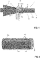
- figure 1 shows related to figure 2 an embodiment of a catheter 1 according to the invention, with an outer shaft 10 which extends from a proximal end section 10a to a distal end section (cut off, not shown) of the outer shaft 10 and has an outer side 10b.
- Proximal and distal mean here in the usual way that the proximal end section 10a is located closer to the doctor or user of the catheter 1, with the outer shaft 10 being inserted into the relevant vessel of the patient with the distal end section first.
- the catheter 1 also has a connector 2, which is connected to the proximal end section 10a of the outer shaft 10 or is molded onto it or is suitably formed on it and is designed to produce a fluid-conducting flow connection with a corresponding further connector.
- the connector 2 can, for example, be designed as a Luer lock connector and is fluidically connected to a lumen 20 of the outer shaft 10, through which, for example, a flow medium can be introduced into a balloon connected distally to the outer shaft 10 (e.g. to unfold the balloon).
- the connector 2 preferably has or is formed from a material processed, for example, by injection molding or a comparable shaping process, in which the proximal end section 10a of the outer shaft 10 is embedded together with a printed circuit board 3, with electrical conductors on the outside 10b of the outer shaft 10 11 are printed, each contacting an associated conductor track 12 of the printed circuit board 3, so that the conductors 11 are each electrically conductively connected to the respectively associated conductor track 12.
- the conductors 11 are conductors 11 printed from an electrically conductive ink.
- the conductor tracks 12 each have an area 12a in which the respective conductor track 12 is arranged on a surface 3a of the circuit board 3 and overlaps there with the associated printed conductor 11, so that electrically conductive contacts between the conductor tracks 12 and the conductors 11 result.
- the surface 3a of the printed circuit board 3 faces the outside 10b of the outer shaft 10, on which the conductors 11 are printed.
- the printed circuit board 3 would actually cover the underlying sections of the conductors 11 or conductor tracks 12. These are nevertheless drawn in to identify the structure.
- the printed circuit board 3 preferably has an angular shape, with a first section 30 of the printed circuit board 3 running at an angle, in particular at right angles, to a second section 31 of the printed circuit board 3 .
- Said overlapping areas 12a are provided at one end of the first section 30, whereas an end section of the second section 31 of the printed circuit board 3 is connected to a connector 4, via which the conductor tracks 12 (and thus the conductors 11) can be contacted in an electrically conductive manner.
- the conductor tracks 12 Preferably, at least in the areas 12a, the conductor tracks 12 have a width that is greater than a width of the conductor 11 perpendicular to the longitudinal direction of the conductor 11 or conductor tracks 12.
- the printed circuit board 3 can be formed from a polyimide, for example, and can have a thickness in the range from 0.03 mm to 0.1 mm, in particular 0.05 mm.
- the conductor tracks 12 can be etched in a known manner.
- the male or female connector 4 is prepared with a circuit board 3 in advance.
- the contact connections between the conductor tracks 12 of the printed circuit board 3 and the printed ink lines 11 are realized or maintained due to the pressure and the form fit of the material of the connector 2.
- a possible course of the method for manufacturing the catheter 1 is in the Figures 2 to 6 played back.
- the outer shaft 10 of the catheter 1 can be prepared by printing the necessary conductors 11 onto the outside 10b of the outer shaft with the aid of electrically conductive ink.
- the width, thickness and the ink material can be varied depending on the requirements (cf. figure 2 ).
- the printed circuit board 3 is provided (for example made of polyimide film, 0.05 mm thick) and the necessary conductor tracks 12 are etched or are formed thereon.
- the width of the conductor tracks 12 should preferably be greater than the width of the printed lines 11 (cf. 3 ).
- the printed circuit board 3 is connected to a connector 4 (e.g. by soldering).
- a connector 4 e.g. by soldering
- an HDMI-D connector with a width of 6.4 mm and a height of 2.8 mm can be used as the connector 4 .
- the circuit board 3 is then together with the connector 4 according to figure 4 fixed on the outside 10b of the outer socket 10 (for example by means of a shrink tube), so that the above-described overlap between the conductor tracks 12 and the printed lines 11 on the outer socket 10 results.
- the prepared arrangement according to figure 4 (PCB 3 with connector 4 and outer shaft 10) is finally placed in an injection mold and the connector 2 is molded onto the assembly.
- the heat-shrink tubing which is preferably made of thin polytetrafluoroethylene, is not removed but overmolded.
- a possible embodiment of the connector 2 is in the Figures 5 and 6 shown, in which case the connector 2 is designed as a Luer lock connector.
- Other connector types can of course also be realized with the invention.
- FIGS 5 and 6 each show the connector 4 for better visibility extends schematically in the plane of the page. In the figure 6 the connector 4 would actually extend perpendicularly to the plane of the page.
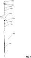
- FIG 7 shows an embodiment of the invention as a catheter 101 for the implantation of a self-expanding stent 150.
- the catheter 101 has two mutually movable catheter shafts 110a and 110b, wherein the self-expanding stent 150 arranged between the outer and inner shaft 110b is released by pulling back the outer shaft 110a.
- both the outer shaft 110a and the inner shaft 110b have a connector 120a or 120b at their proximal end.
- the two connectors 120a, 120b are designed in such a way that a fluid for flushing the lumen can be introduced via them (connector 120a is designed for supplying a fluid for flushing the lumen between outer shaft 110a and inner shaft 110b, connector 120b is for supplying a fluid to the Flushing the lumen of the inner shaft 110b configured).
- Connectors 120a and 120b are analogous to the embodiment of FIGS Figures 1 to 4 designed to connect the printed electrical conductors 111a and 111b on the catheter shafts 110a and 10b via a printed circuit board to the respective plug connectors 104a and 104b.
- the present invention advantageously offers a "two in one design” in which, for example, a Luer connector is provided with a second function (electrical connection between circuit board/connector and printed lines), which improves handling for the doctor.
- the invention also enables a secure electrical connection between catheter-side printed lines and an external component (e.g. measuring device, power supply, etc.) to be connected thereto.
- an external component e.g. measuring device, power supply, etc.
Landscapes
- Health & Medical Sciences (AREA)
- Life Sciences & Earth Sciences (AREA)
- Engineering & Computer Science (AREA)
- Biomedical Technology (AREA)
- Veterinary Medicine (AREA)
- Animal Behavior & Ethology (AREA)
- Public Health (AREA)
- Heart & Thoracic Surgery (AREA)
- General Health & Medical Sciences (AREA)
- Hematology (AREA)
- Anesthesiology (AREA)
- Pulmonology (AREA)
- Biophysics (AREA)
- Cardiology (AREA)
- Oral & Maxillofacial Surgery (AREA)
- Transplantation (AREA)
- Vascular Medicine (AREA)
- Media Introduction/Drainage Providing Device (AREA)
Claims (16)
- Cathéter (1) muni- d'une tige de cathéter (10, 110a, 110b) qui s'étend à partir d'un segment d'extrémité proximal (10a) jusqu'à un segment d'extrémité distal de la tige de cathéter (10, 110a, 110b) et présente une face extérieure (10b), et- d'une jonction (2, 120a, 120b) reliée avec le segment d'extrémité proximal (10a) de la tige de cathéter (10, 110a, 110b),caractérisé en ce que
la jonction (2, 120a, 120b) présente un matériau dont est entouré le segment d'extrémité proximal (10a) de la tige de cathéter (10, 110a, 110b), au moins un conducteur électrique (11, 111a, 111b) étant imprimé sur la face extérieure (10b) de la tige de cathéter (10, 110a, 110b), l'au moins un conducteur électrique (11, 111a, 111b) étant en contact avec une piste conductrice (12) d'une plaque conductrice (3) qui est incorporée dans le matériau de la jonction (2, 120a, 120b), de sorte que l'au moins un conducteur électrique (11, 111a, 111b) et l'au moins une piste conductrice (12) sont reliés électriquement de manière conductrice. - Cathéter selon la revendication 1, caractérisé en ce que l'au moins un conducteur électrique (11, 111a, 111b) est formé à base d'une encre conductrice durcie électriquement.
- Cathéter selon la revendication 1 ou la revendication 2, caractérisé en ce que le segment d'extrémité proximal (10a) de la tige de cathéter (10, 110a, 110b) a été pulvérisé tout autour avec le matériau de la jonction (2, 120a, 120b).
- Cathéter selon l'une des revendications précédentes, caractérisé en ce que le matériau de la jonction (2, 120a, 120b) est à base d'une matière thermoplastique.
- Cathéter selon l'une des revendications précédentes, caractérisé en ce que l'au moins un conducteur électrique (11, 111a, 111b) et la piste conductrice (12) sont disposés de manière superposée.
- Cathéter selon la revendication 5, caractérisé en ce que la piste conductrice (12), dans une plage (12a) de la piste conductrice (12), dans laquelle la piste conductrice (12) se superpose avec l'au moins un conducteur électrique (11, 111a, 111b), est disposée sur une surface (3a) de la plaque conductrice (3), la surface (3a) étant orientée vers la face extérieure (10b) de la tige de cathéter (10, 110a, 110b).
- Cathéter selon l'une des revendications précédentes, caractérisé en ce que la plaque conductrice (3) présente un premier segment et un deuxième segment (30, 31) relié à celui-ci, les deux segments (30, 31) étant disposés en faisant un angle l'un par rapport à l'autre.
- Cathéter selon la revendication 6 ou selon la revendication 7, dans la mesure où elle est reliée avec la revendication 7, caractérisé en ce que ladite plage (12a) de la piste conductrice (12) est disposée à une extrémité du premier segment (30).
- Cathéter selon l'une des revendications précédentes, caractérisé en ce que la plaque conductrice (3) est reliée avec un connecteur (4, 104a, 104b) par lequel la piste conductrice (12) peut être mise en contact de manière électriquement conductrice.
- Cathéter selon les revendications 7 et 9, caractérisé en ce que le connecteur (4, 104a, 104) est relié avec un segment d'extrémité du deuxième segment (31) de la plaque conductrice (3).
- Cathéter selon la revendication 6 ou selon l'une des revendications 7 à 10, dans la mesure où elles sont reliées à la revendication 6, caractérisé en ce que la piste conductrice (12) présente, dans ladite plage (12a) de la piste conductrice (12), une largeur qui est supérieure à une largeur de l'au moins un conducteur électrique (11, 111a, 111b).
- Cathéter selon l'une des revendications précédentes, caractérisé en ce que la plaque conductrice (3) est constituée de polyimide et/ou la plaque conductrice (3) présente une épaisseur dans la plage de 0,03 mm à 0,1 mm.
- Cathéter selon l'une des revendications précédentes, caractérisé en ce que la tige de cathéter (10, 110a, 110b) est une tige extérieure (10a) d'un cathéter de ballonnet et la jonction (2) est conçue pour l'établissement d'une liaison d'écoulement conductrice de fluide avec une autre jonction correspondante.
- Procédé de fabrication d'un cathéter (1) présentant les étapes :- d'impression d'au moins un conducteur électrique (11, 111a, 111b) sur une face extérieure (10b) d'une tige de cathéter (10, 110a, 110b) du cathéter (1) avec une encre électriquement conductrice,- de mise en place d'une plaque conductrice (3) qui présente au moins une piste conductrice (12),- de disposition de la plaque conductrice (3) sur la face extérieure (10b) de la tige de cathéter (10, 110a, 110b) dans la zone d'un segment d'extrémité proximal (10a) de la tige de cathéter (10, 110a, 110b) de sorte que la piste conductrice (12) entre en contact avec l'au moins un conducteur électrique (11, 111a, 111b), et- l'entourage de la plaque conductrice (3) et du segment d'extrémité proximal (10a) de la tige de cathéter (10, 110a, 110b) avec un matériau pour la formation d'une jonction (2, 102a, 102b) reliée avec le segment d'extrémité proximal (10a) de la tige de cathéter (10, 110a, 110b).
- Procédé selon la revendication 14, dans lequel un connecteur (4, 104a, 104b) est relié avec la plaque conductrice (3) de sorte que la piste conductrice (12) puisse être mise en contact via le connecteur (4, 104a, 104b), dans lequel, en particulier, le connecteur (4, 104a, 104b) est relié avec la plaque conductrice (3) avant que la plaque conductrice (3) ne soit disposée sur la face extérieure (10b) du segment d'extrémité proximal (10a) de la tige de cathéter (10, 110a, 110b).
- Procédé selon la revendication 14 ou la revendication 15, dans lequel, pour l'entourage du segment d'extrémité proximal (10a) de la tige de cathéter (10, 110a, 110b) et de la plaque conductrice (3) avec ledit matériau, le segment d'extrémité proximal (10a) de la tige de cathéter (10, 110a, 110b) et la plaque conductrice (3) sont disposés dans un moule d'injection et sont pulvérisés tout autour dans le moule d'injection avec le matériau.
Priority Applications (5)
| Application Number | Priority Date | Filing Date | Title |
|---|---|---|---|
| EP19191879.6A EP3777946B1 (fr) | 2019-08-15 | 2019-08-15 | Système luer-lock pour cathéters à ballonnet numérique |
| EP20743134.7A EP4013478A1 (fr) | 2019-08-15 | 2020-07-20 | Système de vis luer pour cathéters à ballonnet numériques |
| CN202080057345.4A CN114222546B (zh) | 2019-08-15 | 2020-07-20 | 用于数字球囊导管的鲁尔锁系统 |
| US17/630,219 US20220280749A1 (en) | 2019-08-15 | 2020-07-20 | Catheter having connector with electrical conductor connections |
| PCT/EP2020/070428 WO2021028154A1 (fr) | 2019-08-15 | 2020-07-20 | Système de vis luer pour cathéters à ballonnet numériques |
Applications Claiming Priority (1)
| Application Number | Priority Date | Filing Date | Title |
|---|---|---|---|
| EP19191879.6A EP3777946B1 (fr) | 2019-08-15 | 2019-08-15 | Système luer-lock pour cathéters à ballonnet numérique |
Publications (2)
| Publication Number | Publication Date |
|---|---|
| EP3777946A1 EP3777946A1 (fr) | 2021-02-17 |
| EP3777946B1 true EP3777946B1 (fr) | 2023-01-18 |
Family
ID=67658948
Family Applications (2)
| Application Number | Title | Priority Date | Filing Date |
|---|---|---|---|
| EP19191879.6A Active EP3777946B1 (fr) | 2019-08-15 | 2019-08-15 | Système luer-lock pour cathéters à ballonnet numérique |
| EP20743134.7A Withdrawn EP4013478A1 (fr) | 2019-08-15 | 2020-07-20 | Système de vis luer pour cathéters à ballonnet numériques |
Family Applications After (1)
| Application Number | Title | Priority Date | Filing Date |
|---|---|---|---|
| EP20743134.7A Withdrawn EP4013478A1 (fr) | 2019-08-15 | 2020-07-20 | Système de vis luer pour cathéters à ballonnet numériques |
Country Status (4)
| Country | Link |
|---|---|
| US (1) | US20220280749A1 (fr) |
| EP (2) | EP3777946B1 (fr) |
| CN (1) | CN114222546B (fr) |
| WO (1) | WO2021028154A1 (fr) |
Families Citing this family (2)
| Publication number | Priority date | Publication date | Assignee | Title |
|---|---|---|---|---|
| US11931066B2 (en) * | 2021-02-25 | 2024-03-19 | Avent, Inc. | Directly connected smart invasive medical device assembly |
| US20240181211A1 (en) * | 2022-12-01 | 2024-06-06 | Freudenberg Medical, Llc | Handle assembly including a smart catheter ring connector |
Family Cites Families (20)
| Publication number | Priority date | Publication date | Assignee | Title |
|---|---|---|---|---|
| US4163593A (en) * | 1977-09-22 | 1979-08-07 | Consolidated Foods Corporation | Separable hose coupling |
| US6090052A (en) * | 1997-03-25 | 2000-07-18 | Radi Medical Systems Ab | Guide wire having a male connector |
| US7713260B2 (en) * | 2003-09-11 | 2010-05-11 | Cook Incorporated | Catheter having an overmolded hub |
| US7229437B2 (en) * | 2003-09-22 | 2007-06-12 | St. Jude Medical, Atrial Fibrillation Division, Inc. | Medical device having integral traces and formed electrodes |
| US8147486B2 (en) * | 2003-09-22 | 2012-04-03 | St. Jude Medical, Atrial Fibrillation Division, Inc. | Medical device with flexible printed circuit |
| US20150105659A1 (en) * | 2008-11-11 | 2015-04-16 | Covidien Lp | Energy delivery device and methods of use |
| US8206374B2 (en) * | 2010-03-15 | 2012-06-26 | Medtronic Vascular, Inc. | Catheter having improved traceability |
| CN103282076B (zh) * | 2010-12-27 | 2016-05-11 | 导管治疗有限公司 | 模块化导管 |
| KR101920129B1 (ko) * | 2013-10-14 | 2018-11-19 | 지-콘 메뉴팩츄어링 인코포레이티드 | 모듈형 모바일 룸을 연결하기 위한 유닛 |
| US10945786B2 (en) * | 2013-10-18 | 2021-03-16 | Boston Scientific Scimed, Inc. | Balloon catheters with flexible conducting wires and related methods of use and manufacture |
| US9877729B2 (en) * | 2013-12-20 | 2018-01-30 | Microvention, Inc. | Catheter system |
| US20150223908A1 (en) * | 2014-02-13 | 2015-08-13 | Jody Westerfeld | System and Method For Simultaneous Deployment of a Plurality of Fiducials |
| US9833802B2 (en) * | 2014-06-27 | 2017-12-05 | Pulse Finland Oy | Methods and apparatus for conductive element deposition and formation |
| US20160270732A1 (en) * | 2015-03-17 | 2016-09-22 | Cathprint Ab | Low profile medical device with bonded base for electrical components |
| US20160228061A1 (en) * | 2015-02-10 | 2016-08-11 | Cathprint Ab | Low profile medical device with integrated flexible circuit and methods of making the same |
| US10653480B2 (en) * | 2016-04-28 | 2020-05-19 | Biosense Webster (Israel) Ltd. | Method for constructing irrigated balloon catheter with flexible circuit electrode assembly |
| JP7239466B2 (ja) * | 2016-09-30 | 2023-03-14 | コーニンクレッカ フィリップス エヌ ヴェ | 管腔内撮像装置 |
| US11083872B2 (en) * | 2017-02-21 | 2021-08-10 | Microvention, Inc. | Electrical catheter |
| US10532187B2 (en) * | 2017-10-17 | 2020-01-14 | Biosense Webster (Israel) Ltd. | Reusable catheter handle system |
| US10916903B2 (en) * | 2018-02-04 | 2021-02-09 | Creganna Unlimited Company | System having a cable assembly and plug and receptacle connectors |
-
2019
- 2019-08-15 EP EP19191879.6A patent/EP3777946B1/fr active Active
-
2020
- 2020-07-20 CN CN202080057345.4A patent/CN114222546B/zh active Active
- 2020-07-20 US US17/630,219 patent/US20220280749A1/en active Pending
- 2020-07-20 WO PCT/EP2020/070428 patent/WO2021028154A1/fr not_active Ceased
- 2020-07-20 EP EP20743134.7A patent/EP4013478A1/fr not_active Withdrawn
Also Published As
| Publication number | Publication date |
|---|---|
| US20220280749A1 (en) | 2022-09-08 |
| WO2021028154A1 (fr) | 2021-02-18 |
| CN114222546B (zh) | 2024-09-24 |
| CN114222546A (zh) | 2022-03-22 |
| EP3777946A1 (fr) | 2021-02-17 |
| EP4013478A1 (fr) | 2022-06-22 |
Similar Documents
| Publication | Publication Date | Title |
|---|---|---|
| DE69924082T2 (de) | Aktives schlankes Röhrchen und Verfahren zur Herstellung | |
| EP3777946B1 (fr) | Système luer-lock pour cathéters à ballonnet numérique | |
| WO2015082328A1 (fr) | Tête d'endoscope et endoscope | |
| EP3551271A1 (fr) | Technique de surmoulage pour conception d'un introducteur détachable (type « peel-away ») | |
| CH622870A5 (fr) | ||
| EP3423148B1 (fr) | Électrode à gaine implantable | |
| EP0824930A2 (fr) | Méthode de fabrication d'un cathéter inséré au moulage avec fenêtre de fixation | |
| DE112015002449T5 (de) | Katheter, Katheterherstellungsformteil, Katheterherstellungsverfahren | |
| DE4137628C1 (fr) | ||
| WO2015172890A1 (fr) | Système de mesure médicotechnique et procédé pour le fabriquer | |
| WO2017215916A1 (fr) | Ensemble capteur | |
| EP2250010B1 (fr) | Capteur pour l'enregistrement d'une grandeur physique et procédé de fabrication de capteur | |
| DE60110791T2 (de) | Vorrichtung aus thermoplastischem material und zugehöriges zweistufiges giessverfahren | |
| WO2018108364A1 (fr) | Dispositif de commande de transmission, notamment pour un véhicule à moteur, et procédé de fabrication d'un boîtier de connexion | |
| DE3820348A1 (de) | Verfahren und vorrichtung zum herstellen eines gehaeuses fuer einen sensor und katheter mit sensorgehaeuse | |
| EP1174237B1 (fr) | Appareil électrique avec boítier en matériau polymère renforcé | |
| EP2384785B1 (fr) | Procédé de fabrication d'une structure d'électrodes et structure d'électrodes pour une interface neuronale | |
| DE10133731C2 (de) | Verfahren zum Herstellen eines elektrischen Endprodukts, welches Löt-oder Schweißstellen aufweist | |
| DE102012200918B4 (de) | Verfahren zum Herstellen einer thermoplastischen Vorrichtung mit einer Steckerkavität | |
| EP4062848B1 (fr) | Instrument médical et procédé destinés à la fabrication de tels instruments | |
| DE102009026460A1 (de) | Elektrische Kontaktierung und Verfahren zur Herstellung einer elektrischen Kontaktierung | |
| DE102018105774B4 (de) | Dichtumspritzter elektrischer Leiter und Verfahren zu dessen Herstellung | |
| DE19804159B4 (de) | Verbindungsmuffe und Verfahren zu ihrer Herstellung | |
| WO2017215915A1 (fr) | Dispositif de détection et procédé de production d'un dispositif de détection | |
| DE102008003372B4 (de) | Verfahren zur Herstellung eines mehrlagigen zwei- oder dreidimensionalen Schaltungsträgers |
Legal Events
| Date | Code | Title | Description |
|---|---|---|---|
| PUAI | Public reference made under article 153(3) epc to a published international application that has entered the european phase |
Free format text: ORIGINAL CODE: 0009012 |
|
| STAA | Information on the status of an ep patent application or granted ep patent |
Free format text: STATUS: THE APPLICATION HAS BEEN PUBLISHED |
|
| AK | Designated contracting states |
Kind code of ref document: A1 Designated state(s): AL AT BE BG CH CY CZ DE DK EE ES FI FR GB GR HR HU IE IS IT LI LT LU LV MC MK MT NL NO PL PT RO RS SE SI SK SM TR |
|
| AX | Request for extension of the european patent |
Extension state: BA ME |
|
| STAA | Information on the status of an ep patent application or granted ep patent |
Free format text: STATUS: REQUEST FOR EXAMINATION WAS MADE |
|
| 17P | Request for examination filed |
Effective date: 20210805 |
|
| RBV | Designated contracting states (corrected) |
Designated state(s): AL AT BE BG CH CY CZ DE DK EE ES FI FR GB GR HR HU IE IS IT LI LT LU LV MC MK MT NL NO PL PT RO RS SE SI SK SM TR |
|
| GRAP | Despatch of communication of intention to grant a patent |
Free format text: ORIGINAL CODE: EPIDOSNIGR1 |
|
| STAA | Information on the status of an ep patent application or granted ep patent |
Free format text: STATUS: GRANT OF PATENT IS INTENDED |
|
| INTG | Intention to grant announced |
Effective date: 20220414 |
|
| GRAJ | Information related to disapproval of communication of intention to grant by the applicant or resumption of examination proceedings by the epo deleted |
Free format text: ORIGINAL CODE: EPIDOSDIGR1 |
|
| STAA | Information on the status of an ep patent application or granted ep patent |
Free format text: STATUS: REQUEST FOR EXAMINATION WAS MADE |
|
| INTC | Intention to grant announced (deleted) | ||
| GRAP | Despatch of communication of intention to grant a patent |
Free format text: ORIGINAL CODE: EPIDOSNIGR1 |
|
| STAA | Information on the status of an ep patent application or granted ep patent |
Free format text: STATUS: GRANT OF PATENT IS INTENDED |
|
| INTG | Intention to grant announced |
Effective date: 20221018 |
|
| GRAS | Grant fee paid |
Free format text: ORIGINAL CODE: EPIDOSNIGR3 |
|
| GRAA | (expected) grant |
Free format text: ORIGINAL CODE: 0009210 |
|
| STAA | Information on the status of an ep patent application or granted ep patent |
Free format text: STATUS: THE PATENT HAS BEEN GRANTED |
|
| AK | Designated contracting states |
Kind code of ref document: B1 Designated state(s): AL AT BE BG CH CY CZ DE DK EE ES FI FR GB GR HR HU IE IS IT LI LT LU LV MC MK MT NL NO PL PT RO RS SE SI SK SM TR |
|
| REG | Reference to a national code |
Ref country code: GB Ref legal event code: FG4D Free format text: NOT ENGLISH |
|
| REG | Reference to a national code |
Ref country code: DE Ref legal event code: R096 Ref document number: 502019006810 Country of ref document: DE |
|
| REG | Reference to a national code |
Ref country code: CH Ref legal event code: EP |
|
| REG | Reference to a national code |
Ref country code: AT Ref legal event code: REF Ref document number: 1544336 Country of ref document: AT Kind code of ref document: T Effective date: 20230215 Ref country code: IE Ref legal event code: FG4D Free format text: LANGUAGE OF EP DOCUMENT: GERMAN |
|
| REG | Reference to a national code |
Ref country code: LT Ref legal event code: MG9D |
|
| REG | Reference to a national code |
Ref country code: NL Ref legal event code: MP Effective date: 20230118 |
|
| PG25 | Lapsed in a contracting state [announced via postgrant information from national office to epo] |
Ref country code: NL Free format text: LAPSE BECAUSE OF FAILURE TO SUBMIT A TRANSLATION OF THE DESCRIPTION OR TO PAY THE FEE WITHIN THE PRESCRIBED TIME-LIMIT Effective date: 20230118 |
|
| P01 | Opt-out of the competence of the unified patent court (upc) registered |
Effective date: 20230612 |
|
| PG25 | Lapsed in a contracting state [announced via postgrant information from national office to epo] |
Ref country code: RS Free format text: LAPSE BECAUSE OF FAILURE TO SUBMIT A TRANSLATION OF THE DESCRIPTION OR TO PAY THE FEE WITHIN THE PRESCRIBED TIME-LIMIT Effective date: 20230118 Ref country code: PT Free format text: LAPSE BECAUSE OF FAILURE TO SUBMIT A TRANSLATION OF THE DESCRIPTION OR TO PAY THE FEE WITHIN THE PRESCRIBED TIME-LIMIT Effective date: 20230518 Ref country code: NO Free format text: LAPSE BECAUSE OF FAILURE TO SUBMIT A TRANSLATION OF THE DESCRIPTION OR TO PAY THE FEE WITHIN THE PRESCRIBED TIME-LIMIT Effective date: 20230418 Ref country code: LV Free format text: LAPSE BECAUSE OF FAILURE TO SUBMIT A TRANSLATION OF THE DESCRIPTION OR TO PAY THE FEE WITHIN THE PRESCRIBED TIME-LIMIT Effective date: 20230118 Ref country code: LT Free format text: LAPSE BECAUSE OF FAILURE TO SUBMIT A TRANSLATION OF THE DESCRIPTION OR TO PAY THE FEE WITHIN THE PRESCRIBED TIME-LIMIT Effective date: 20230118 Ref country code: HR Free format text: LAPSE BECAUSE OF FAILURE TO SUBMIT A TRANSLATION OF THE DESCRIPTION OR TO PAY THE FEE WITHIN THE PRESCRIBED TIME-LIMIT Effective date: 20230118 Ref country code: ES Free format text: LAPSE BECAUSE OF FAILURE TO SUBMIT A TRANSLATION OF THE DESCRIPTION OR TO PAY THE FEE WITHIN THE PRESCRIBED TIME-LIMIT Effective date: 20230118 |
|
| PG25 | Lapsed in a contracting state [announced via postgrant information from national office to epo] |
Ref country code: SE Free format text: LAPSE BECAUSE OF FAILURE TO SUBMIT A TRANSLATION OF THE DESCRIPTION OR TO PAY THE FEE WITHIN THE PRESCRIBED TIME-LIMIT Effective date: 20230118 Ref country code: PL Free format text: LAPSE BECAUSE OF FAILURE TO SUBMIT A TRANSLATION OF THE DESCRIPTION OR TO PAY THE FEE WITHIN THE PRESCRIBED TIME-LIMIT Effective date: 20230118 Ref country code: IS Free format text: LAPSE BECAUSE OF FAILURE TO SUBMIT A TRANSLATION OF THE DESCRIPTION OR TO PAY THE FEE WITHIN THE PRESCRIBED TIME-LIMIT Effective date: 20230518 Ref country code: GR Free format text: LAPSE BECAUSE OF FAILURE TO SUBMIT A TRANSLATION OF THE DESCRIPTION OR TO PAY THE FEE WITHIN THE PRESCRIBED TIME-LIMIT Effective date: 20230419 Ref country code: FI Free format text: LAPSE BECAUSE OF FAILURE TO SUBMIT A TRANSLATION OF THE DESCRIPTION OR TO PAY THE FEE WITHIN THE PRESCRIBED TIME-LIMIT Effective date: 20230118 |
|
| REG | Reference to a national code |
Ref country code: DE Ref legal event code: R097 Ref document number: 502019006810 Country of ref document: DE |
|
| PG25 | Lapsed in a contracting state [announced via postgrant information from national office to epo] |
Ref country code: SM Free format text: LAPSE BECAUSE OF FAILURE TO SUBMIT A TRANSLATION OF THE DESCRIPTION OR TO PAY THE FEE WITHIN THE PRESCRIBED TIME-LIMIT Effective date: 20230118 Ref country code: RO Free format text: LAPSE BECAUSE OF FAILURE TO SUBMIT A TRANSLATION OF THE DESCRIPTION OR TO PAY THE FEE WITHIN THE PRESCRIBED TIME-LIMIT Effective date: 20230118 Ref country code: EE Free format text: LAPSE BECAUSE OF FAILURE TO SUBMIT A TRANSLATION OF THE DESCRIPTION OR TO PAY THE FEE WITHIN THE PRESCRIBED TIME-LIMIT Effective date: 20230118 Ref country code: DK Free format text: LAPSE BECAUSE OF FAILURE TO SUBMIT A TRANSLATION OF THE DESCRIPTION OR TO PAY THE FEE WITHIN THE PRESCRIBED TIME-LIMIT Effective date: 20230118 Ref country code: CZ Free format text: LAPSE BECAUSE OF FAILURE TO SUBMIT A TRANSLATION OF THE DESCRIPTION OR TO PAY THE FEE WITHIN THE PRESCRIBED TIME-LIMIT Effective date: 20230118 |
|
| PLBE | No opposition filed within time limit |
Free format text: ORIGINAL CODE: 0009261 |
|
| STAA | Information on the status of an ep patent application or granted ep patent |
Free format text: STATUS: NO OPPOSITION FILED WITHIN TIME LIMIT |
|
| PG25 | Lapsed in a contracting state [announced via postgrant information from national office to epo] |
Ref country code: SK Free format text: LAPSE BECAUSE OF FAILURE TO SUBMIT A TRANSLATION OF THE DESCRIPTION OR TO PAY THE FEE WITHIN THE PRESCRIBED TIME-LIMIT Effective date: 20230118 |
|
| 26N | No opposition filed |
Effective date: 20231019 |
|
| PG25 | Lapsed in a contracting state [announced via postgrant information from national office to epo] |
Ref country code: SI Free format text: LAPSE BECAUSE OF FAILURE TO SUBMIT A TRANSLATION OF THE DESCRIPTION OR TO PAY THE FEE WITHIN THE PRESCRIBED TIME-LIMIT Effective date: 20230118 |
|
| PG25 | Lapsed in a contracting state [announced via postgrant information from national office to epo] |
Ref country code: MC Free format text: LAPSE BECAUSE OF FAILURE TO SUBMIT A TRANSLATION OF THE DESCRIPTION OR TO PAY THE FEE WITHIN THE PRESCRIBED TIME-LIMIT Effective date: 20230118 |
|
| PG25 | Lapsed in a contracting state [announced via postgrant information from national office to epo] |
Ref country code: MC Free format text: LAPSE BECAUSE OF FAILURE TO SUBMIT A TRANSLATION OF THE DESCRIPTION OR TO PAY THE FEE WITHIN THE PRESCRIBED TIME-LIMIT Effective date: 20230118 |
|
| PG25 | Lapsed in a contracting state [announced via postgrant information from national office to epo] |
Ref country code: LU Free format text: LAPSE BECAUSE OF NON-PAYMENT OF DUE FEES Effective date: 20230815 |
|
| PG25 | Lapsed in a contracting state [announced via postgrant information from national office to epo] |
Ref country code: LU Free format text: LAPSE BECAUSE OF NON-PAYMENT OF DUE FEES Effective date: 20230815 |
|
| REG | Reference to a national code |
Ref country code: BE Ref legal event code: MM Effective date: 20230831 |
|
| REG | Reference to a national code |
Ref country code: IE Ref legal event code: MM4A |
|
| PG25 | Lapsed in a contracting state [announced via postgrant information from national office to epo] |
Ref country code: IT Free format text: LAPSE BECAUSE OF FAILURE TO SUBMIT A TRANSLATION OF THE DESCRIPTION OR TO PAY THE FEE WITHIN THE PRESCRIBED TIME-LIMIT Effective date: 20230118 |
|
| PG25 | Lapsed in a contracting state [announced via postgrant information from national office to epo] |
Ref country code: IE Free format text: LAPSE BECAUSE OF NON-PAYMENT OF DUE FEES Effective date: 20230815 |
|
| PG25 | Lapsed in a contracting state [announced via postgrant information from national office to epo] |
Ref country code: IE Free format text: LAPSE BECAUSE OF NON-PAYMENT OF DUE FEES Effective date: 20230815 |
|
| PG25 | Lapsed in a contracting state [announced via postgrant information from national office to epo] |
Ref country code: BE Free format text: LAPSE BECAUSE OF NON-PAYMENT OF DUE FEES Effective date: 20230831 |
|
| PGFP | Annual fee paid to national office [announced via postgrant information from national office to epo] |
Ref country code: CH Payment date: 20240901 Year of fee payment: 6 |
|
| PG25 | Lapsed in a contracting state [announced via postgrant information from national office to epo] |
Ref country code: BG Free format text: LAPSE BECAUSE OF FAILURE TO SUBMIT A TRANSLATION OF THE DESCRIPTION OR TO PAY THE FEE WITHIN THE PRESCRIBED TIME-LIMIT Effective date: 20230118 |
|
| PG25 | Lapsed in a contracting state [announced via postgrant information from national office to epo] |
Ref country code: BG Free format text: LAPSE BECAUSE OF FAILURE TO SUBMIT A TRANSLATION OF THE DESCRIPTION OR TO PAY THE FEE WITHIN THE PRESCRIBED TIME-LIMIT Effective date: 20230118 |
|
| REG | Reference to a national code |
Ref country code: DE Ref legal event code: R082 Ref document number: 502019006810 Country of ref document: DE Representative=s name: WSL PATENTANWAELTE PARTNERSCHAFT MBB, DE |
|
| PG25 | Lapsed in a contracting state [announced via postgrant information from national office to epo] |
Ref country code: CY Free format text: LAPSE BECAUSE OF FAILURE TO SUBMIT A TRANSLATION OF THE DESCRIPTION OR TO PAY THE FEE WITHIN THE PRESCRIBED TIME-LIMIT; INVALID AB INITIO Effective date: 20190815 |
|
| PG25 | Lapsed in a contracting state [announced via postgrant information from national office to epo] |
Ref country code: HU Free format text: LAPSE BECAUSE OF FAILURE TO SUBMIT A TRANSLATION OF THE DESCRIPTION OR TO PAY THE FEE WITHIN THE PRESCRIBED TIME-LIMIT; INVALID AB INITIO Effective date: 20190815 |
|
| PGFP | Annual fee paid to national office [announced via postgrant information from national office to epo] |
Ref country code: DE Payment date: 20250821 Year of fee payment: 7 |
|
| REG | Reference to a national code |
Ref country code: AT Ref legal event code: MM01 Ref document number: 1544336 Country of ref document: AT Kind code of ref document: T Effective date: 20240815 |
|
| PGFP | Annual fee paid to national office [announced via postgrant information from national office to epo] |
Ref country code: GB Payment date: 20250820 Year of fee payment: 7 |
|
| PG25 | Lapsed in a contracting state [announced via postgrant information from national office to epo] |
Ref country code: AT Free format text: LAPSE BECAUSE OF NON-PAYMENT OF DUE FEES Effective date: 20240815 |
|
| PGFP | Annual fee paid to national office [announced via postgrant information from national office to epo] |
Ref country code: FR Payment date: 20250828 Year of fee payment: 7 |
|
| PG25 | Lapsed in a contracting state [announced via postgrant information from national office to epo] |
Ref country code: TR Free format text: LAPSE BECAUSE OF FAILURE TO SUBMIT A TRANSLATION OF THE DESCRIPTION OR TO PAY THE FEE WITHIN THE PRESCRIBED TIME-LIMIT Effective date: 20230118 |
|
| REG | Reference to a national code |
Ref country code: CH Ref legal event code: H13 Free format text: ST27 STATUS EVENT CODE: U-0-0-H10-H13 (AS PROVIDED BY THE NATIONAL OFFICE) Effective date: 20260324 |
|
| PGFP | Annual fee paid to national office [announced via postgrant information from national office to epo] |
Ref country code: AT Payment date: 20260410 Year of fee payment: 5 |
|
| PG25 | Lapsed in a contracting state [announced via postgrant information from national office to epo] |
Ref country code: CH Free format text: LAPSE BECAUSE OF NON-PAYMENT OF DUE FEES Effective date: 20250831 |