EP3777962B1 - Dispositif rétinien artificiel avec fonction de fluctuation d'image - Google Patents
Dispositif rétinien artificiel avec fonction de fluctuation d'image Download PDFInfo
- Publication number
- EP3777962B1 EP3777962B1 EP18911639.5A EP18911639A EP3777962B1 EP 3777962 B1 EP3777962 B1 EP 3777962B1 EP 18911639 A EP18911639 A EP 18911639A EP 3777962 B1 EP3777962 B1 EP 3777962B1
- Authority
- EP
- European Patent Office
- Prior art keywords
- switch
- artificial retinal
- stimulation
- jittering
- image
- Prior art date
- Legal status (The legal status is an assumption and is not a legal conclusion. Google has not performed a legal analysis and makes no representation as to the accuracy of the status listed.)
- Active
Links
Images


Classifications
-
- A—HUMAN NECESSITIES
- A61—MEDICAL OR VETERINARY SCIENCE; HYGIENE
- A61N—ELECTROTHERAPY; MAGNETOTHERAPY; RADIATION THERAPY; ULTRASOUND THERAPY
- A61N1/00—Electrotherapy; Circuits therefor
- A61N1/18—Applying electric currents by contact electrodes
- A61N1/32—Applying electric currents by contact electrodes alternating or intermittent currents
- A61N1/36—Applying electric currents by contact electrodes alternating or intermittent currents for stimulation
- A61N1/3605—Implantable neurostimulators for stimulating central or peripheral nerve system
- A61N1/36128—Control systems
- A61N1/36146—Control systems specified by the stimulation parameters
- A61N1/36167—Timing, e.g. stimulation onset
-
- A—HUMAN NECESSITIES
- A61—MEDICAL OR VETERINARY SCIENCE; HYGIENE
- A61F—FILTERS IMPLANTABLE INTO BLOOD VESSELS; PROSTHESES; DEVICES PROVIDING PATENCY TO, OR PREVENTING COLLAPSING OF, TUBULAR STRUCTURES OF THE BODY, e.g. STENTS; ORTHOPAEDIC, NURSING OR CONTRACEPTIVE DEVICES; FOMENTATION; TREATMENT OR PROTECTION OF EYES OR EARS; BANDAGES, DRESSINGS OR ABSORBENT PADS; FIRST-AID KITS
- A61F2/00—Filters implantable into blood vessels; Prostheses, i.e. artificial substitutes or replacements for parts of the body; Appliances for connecting them with the body; Devices providing patency to, or preventing collapsing of, tubular structures of the body, e.g. stents
- A61F2/02—Prostheses implantable into the body
- A61F2/14—Eye parts, e.g. lenses or corneal implants; Artificial eyes
-
- A—HUMAN NECESSITIES
- A61—MEDICAL OR VETERINARY SCIENCE; HYGIENE
- A61N—ELECTROTHERAPY; MAGNETOTHERAPY; RADIATION THERAPY; ULTRASOUND THERAPY
- A61N1/00—Electrotherapy; Circuits therefor
- A61N1/02—Details
- A61N1/04—Electrodes
- A61N1/05—Electrodes for implantation or insertion into the body, e.g. heart electrode
- A61N1/0526—Head electrodes
- A61N1/0543—Retinal electrodes
-
- A—HUMAN NECESSITIES
- A61—MEDICAL OR VETERINARY SCIENCE; HYGIENE
- A61N—ELECTROTHERAPY; MAGNETOTHERAPY; RADIATION THERAPY; ULTRASOUND THERAPY
- A61N1/00—Electrotherapy; Circuits therefor
- A61N1/18—Applying electric currents by contact electrodes
- A61N1/32—Applying electric currents by contact electrodes alternating or intermittent currents
- A61N1/36—Applying electric currents by contact electrodes alternating or intermittent currents for stimulation
- A61N1/36046—Applying electric currents by contact electrodes alternating or intermittent currents for stimulation of the eye
-
- A—HUMAN NECESSITIES
- A61—MEDICAL OR VETERINARY SCIENCE; HYGIENE
- A61N—ELECTROTHERAPY; MAGNETOTHERAPY; RADIATION THERAPY; ULTRASOUND THERAPY
- A61N1/00—Electrotherapy; Circuits therefor
- A61N1/18—Applying electric currents by contact electrodes
- A61N1/32—Applying electric currents by contact electrodes alternating or intermittent currents
- A61N1/36—Applying electric currents by contact electrodes alternating or intermittent currents for stimulation
- A61N1/3605—Implantable neurostimulators for stimulating central or peripheral nerve system
- A61N1/36128—Control systems
- A61N1/36146—Control systems specified by the stimulation parameters
- A61N1/36182—Direction of the electrical field, e.g. with sleeve around stimulating electrode
- A61N1/36185—Selection of the electrode configuration
Definitions
- the present disclosure relates to an artificial retinal device, and more particularly to a sub-type artificial retinal based artificial retinal stimulator which includes an image jittering function in order to improve the visual function of a low vision patient.
- the three methods include reducing a distance between eye and object (distance reduction), enlarging the size of the object (size enlargement), and positioning an image large close to eye by using a magnifying telescope, etc. (angle enlargement).
- distance reduction reducing a distance between eye and object
- size enlargement size enlargement
- angle enlargement positioning an image large close to eye by using a magnifying telescope, etc.
- these enlargements often narrow a field of view, change the sense of depth, and break the harmony between the visible sense of vision and movement, making it difficult to perform an appropriate body functional cooperation. Therefore, other methods other than the enlargement must be considered to improve the vision of the low vision patients.
- a reading speed increases when the size of a letter increases.
- the purpose of the present disclosure is to provide an artificial retinal device including an image jittering function in order to improve the visual function of a low vision patient.
- the invention provides an artificial retinal device according to claim 1.
- Embodiments of the invention are defined in the dependent claims.
- a portion is “connected” to another portion, it includes not only “is directly connected” but also “electrically connected” with another element placed therebetween. Meanwhile, in the case where a component is referred to as being “directly connected” to other components, it should be understood that there is no component therebetween. Additionally, when it is mentioned that a portion "includes” an element, it means that the portion does not exclude but further includes other elements unless there is a special opposite mention.
- first, second, third, etc. are used to describe various parts, components, regions, layers, and/or sections, these terms are not limited thereto. These terms are only used to distinguish one part, component, region, layer or section from another part, component, region, layer or section. Thus, a first part, component, region, layer or section to be described below can be referred to as a second part, component, region, layer or section.
- Spatially relative terms such as “under”, “over” and the like, may be used to more easily describe a relationship of one portion to another portion shown in the drawing. These terms are intended to include not only meanings intended in the drawing but other meanings or operations of a device in use. For example, if the device is turned upside down in the drawing, a portion described as being “under” other portions is described as being “over” other portions. Thus, the exemplary term “under” includes both an up direction and a down direction. The device may rotate by 90 degrees or at other angles, and the spatially relative terms are construed accordingly.
- the purpose of these eye movements may be a reaction to neuroadaptation.
- the purpose of these eye movements may be considered to act to temporarily burst a neural spike by shaking a static image formed on the receptive fields of the retinal optic nerve. This can help the parvocellular visual pathways, which have a small receptive field responsible for cognition of delicate parts, to maintain continuously their activities.
- the amplitude of physiological microsaccades is provided as a sufficient amplitude.
- nerves which mainly react to stimuli of low spatial frequency and high temporal frequency and are present in nerve cells around the retina (magnocellular pathways) responsible for a larger receptive field react only at a very short moment when the stimulation occurs and disappears. Therefore, the movement of the retinal image caused by the microsaccades is not sufficient to cause a nerve reaction while watching a still low spatial frequency image. Accordingly, in order to increase the sensitivity to a low spatial frequency image, stimulation with a greater amplitude is required.
- the visual stimulation in the low spatial frequency region processed by the nerve cells around the retina which have such a large receptive field plays a main role in visual information processing, jittering the image formed on the retina at a certain frequency and to a certain size is helpful to the low vision patients.
- the present disclosure provides an artificial retinal stimulator capable of providing the jittering function to help improve recognition capability of patients with low vision.
- An artificial retinal device may be largely divided into two types according to the method for delivering visual stimulation to the artificial retinal stimulator.
- One is a camera type that stimulates a designated electrode by obtaining image information with a camera and by processing the information
- the other is a photodiode type that recognizes light by a photodiode and stimulates an electrode located next to it not just above (not on the same coordinates).
- the photodiode type artificial retinal stimulator since the photodiode has to accept a light signal, an opaque electrode cannot be placed on the photodiode but has to be placed next to it. Strictly speaking, this inevitably leads to inconsistency between an area where light stimulates the retina and an area where the retina is stimulated.
- the patients receiving the artificial retinal stimulator are ultra-low vision patients with low vision of 0.01 or less, the position mismatch of several tens of um to 100 um between the photodiode and the electrode may not cause practical discomfort to patients in life, in terms of using information of very low spatial frequency.
- the positional mismatch between the light receptor and the stimulator which is inherently unavoidable due to such a design principle of the photodiode, can be used by being combined with the image jittering, which is one of vision improvement techniques for low vision patients.
- the camera type stimulator can stimulate the electrode by applying the image jittering during the image processing.
- the photodiode has to implement the image jittering in a circuit.
- two adjacent connected stimulation electrodes and the photodiode located between therebetween are alternately connected by using a switch, so that the image jittering is implemented by alternately transmitting an electrical signal generated by the light stimulation entering the photodiode to the two electrodes.
- a sub-type artificial retinal device is composed of a plurality of pixels, and may be implemented in the form of a two-dimensional array. That is, the sub-type artificial retinal device may be implemented by dividing the retina in a two-dimensional manner and by placing the pixels at each divided point.
- each pixel may include the artificial retinal stimulator and the stimulation electrode.
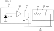
- Fig. 1 shows a structure of one pixel of a general sub-type artificial retinal device.
- one pixel of the general sub-type artificial retinal device may include an artificial retinal stimulator 100 and a stimulation electrode 200.
- the stimulation electrode 200 performs a function of transmitting stimulation from the artificial retinal stimulator 100 to a retinal tissue, and is generally modeled by a resistor 210 and a capacitor 220 connected to ground 300.
- the artificial retinal stimulator 100 is composed of a photodiode 110 and a pulse generator.
- the photodiode 110 senses the intensity of light.
- the pulse generator amplifies a dark current generated by the photodiode 110, converts the amplified dark current into a pulse to be provided to the stimulation electrode 200 and outputs it.
- the pulse generator may be composed of a converter 120 and a driver 130, and in particular, the pulse may be a biphasic pulse.
- a switch 140 may be further provided on the output terminal of the driver 130 of the pulse generator. The switch 140 connects the output terminal of the driver 130 to the ground 300 in order to achieve a charge balance after transmitting a stimulation pulse.
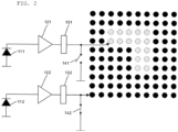
- Fig. 2 shows an example of stimulation in the artificial retinal device composed of a plurality of pixels.
- Fig. 2 as an example, only artificial retinal stimulators for two pixels are shown. However, in practice, the artificial retinal stimulators exist for all pixels.
- the photodiode 111 of a pixel which receives light stimulation of the oblique-lined portions receives the light stimulation and outputs a current.
- the converter 121 and the driver 131 receive the current and output a biphasic pulse.
- the photodiode 112 cannot output the current in portions which are not stimulated, and the switch 142 remains connected such that the output terminal of the driver 132 is connected to the ground 300.
- a conventional artificial retinal device continues the stimulation shown in Fig. 2 without image jittering.
- Figs. 3 and 4 show embodiments in which a stimulation range is changed for the image jittering proposed in the present invention.
- the first stimulation 410 of the "oblique-lined portions” is delivered to the stimulation electrode of the artificial retinal device, and then, in a certain period of time, the stimulation 420 which has moved to the right by one pixel or the stimulation 430 which has moved downward by one pixel is delivered to the stimulation electrode of the artificial retinal device.
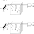
- Fig. 5 shows the artificial retinal stimulator equipped with an image jittering function in accordance with the embodiment of the present disclosure.
- the artificial retinal stimulator further includes a switch 153 between a photodiode 113 and a converter 123 in order to provide the image jittering function.
- the switch 153 transfers the current flowing out from the stimulated photodiode 113 to its own converter 123 and driver 133 for a certain period of time, and then is switched to transmit the current to the converter and the driver of an adjacent artificial retinal stimulator.
- the adjacent artificial retinal stimulator may be located above or below by one pixel or on the left or on the right in a pixel array of the artificial retinal device.
- the switch 153 may transmit the current coming from the photodiode 113 while periodically switching to the converter of the adjacent artificial retinal stimulator and its own converter. That is, even if the same stimulation continues to the photodiode 113, the stimulation electrode to be stimulated is changed between a stimulation electrode 203 corresponding to itself and a stimulation electrode 202 corresponding to the adjacent artificial retinal stimulator. As a result, the image jittering can occur, when viewing the entire artificial retinal device.
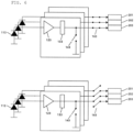
- Fig. 6 shows an artificial retinal stimulator equipped with the image jittering function in accordance with another embodiment of the present disclosure.
- the artificial retinal stimulator further includes a switch 163 on the output terminal of the driver 133 in order to provide the image jittering function. That is, the switch 163 is provided before the stimulation electrodes 201 to 203 that the biphasic pulse output from the driver 133 enters, and the output terminal of the driver 133 is connected to the stimulation electrode 203 corresponding to itself for a certain period of time. Then, the output terminal is connected to the stimulation electrode 202 corresponding to the adjacent artificial retinal stimulator.
- the adjacent artificial retinal stimulator may be located above or below by one pixel or on the left or on the right in a pixel array of the artificial retinal device.
- the switch 163 is periodically switched to transmit the biphasic pulse output from the output terminal of the driver 133 to the stimulation electrode 203 corresponding to itself or the stimulation electrode 202 corresponding to the adjacent artificial retinal stimulator. That is, even if the same stimulation continues to the photodiode 113, the stimulation electrode to be stimulated is changed between a stimulation electrode 203 corresponding to itself and a stimulation electrode 202 corresponding to the adjacent artificial retinal stimulator. As a result, the image jittering can occur, when viewing the entire artificial retinal device.
- Fig. 7 shows a switch structure added for implementing the image jittering function in accordance with the embodiment of the present disclosure.
- a switch added in order to implement the image jittering function may be composed of two semiconductor switches D1 and J1 enabling the output terminal of the artificial retinal stimulator 710 of the N th pixel to be connected to a stimulation electrode 204 of the N th pixel and a stimulation electrode 205 of the (N+1) th .
- the semiconductor switch may be a transistor, a field effect transistor (FET), SCR, TRIAC, or the like.
- the biphasic pulse output from the artificial retinal stimulator 710 of the N th pixel may be applied to the N th stimulation electrode 204. Then, when the semiconductor switch J1 is turned on by applying a high voltage to the semiconductor switch J1 and the semiconductor switch D1 is turned off by applying a low voltage to the semiconductor switch D1, the biphasic pulse output from the artificial retinal stimulator 710 of the N th pixel may be applied to the (N+1) th stimulation electrode 205.
- the biphasic current output from an artificial retinal stimulator 720 of the (N+1) th pixel by two semiconductor switches D2 and J2 may be applied to the stimulation electrode 205 of the (N+1) th pixel or the stimulation electrode of the (N+2) th pixel.
- a separate controller may be included in order to control the on/off of the switch.
- the controller may control such that the two semiconductor switches D1 and J1 or D2 and J2 are periodically turned on/off.
- the controller may control the periodic on/off time according to a preset value.
- the controller may control such that n number of the semiconductor switches D1 to Dn are synchronized and switched from on to off or from off to on simultaneously.
- the controller may control such that n number of other semiconductor switches J1 to Jn are synchronized and switched from on to off or from off to on simultaneously.
- the controller may adjust the periodic on/off time between 0.2 seconds and 1 second. In other words, a period of 1 to 5 Hz can be obtained.
- the controller may reduce a carrier frequency of 2 MHz to 1 to 5 Hz by using a clock divider. Also, in the frequency of jittering, the period may be changed by the patient with an external regulator so as to reflect each individual difference.
- the artificial retinal stimulator and the artificial retinal device including the same as presented in the present disclosure can implement the image jittering function, thereby further improving the visual function of a low vision patient receiving the artificial retinal device.
Landscapes
- Health & Medical Sciences (AREA)
- Animal Behavior & Ethology (AREA)
- Veterinary Medicine (AREA)
- Engineering & Computer Science (AREA)
- Biomedical Technology (AREA)
- Public Health (AREA)
- General Health & Medical Sciences (AREA)
- Life Sciences & Earth Sciences (AREA)
- Radiology & Medical Imaging (AREA)
- Nuclear Medicine, Radiotherapy & Molecular Imaging (AREA)
- Ophthalmology & Optometry (AREA)
- Cardiology (AREA)
- Heart & Thoracic Surgery (AREA)
- Neurosurgery (AREA)
- Neurology (AREA)
- Oral & Maxillofacial Surgery (AREA)
- Transplantation (AREA)
- Vascular Medicine (AREA)
- Prostheses (AREA)
Claims (6)
- Dispositif rétinien artificiel pour produire une fluctuation d'image, le dispositif rétinien artificiel comprenant:une pluralité de stimulateurs rétiniens artificiels (100); etune pluralité d'électrodes de stimulation (200),dans lequel chacun de la pluralité de stimulateurs rétiniens artificiels (100) comprend:une photodiode (113) configurée pour détecter une stimulation de lumière et pour générer un courant sur base d'une intensité de la stimulation de lumière détectée;un générateur d'impulsions (133) configuré pour générer une impulsion sur base du courant généré par la photodiode;un commutateur (143) configuré pour connecter une borne de sortie du générateur d'impulsions et la terre;un commutateur de fluctuation (163, 153) configuré pour sélectionner l'une de la pluralité d'électrodes de stimulation (200) pour transférer l'impulsion générée et la fournir à la borne de sortie du générateur d'impulsions, etle dispositif rétinien artificiel comprend par ailleurs un moyen de commande configuré pour commander l'activation/la désactivation du commutateur de fluctuation de chacun de la pluralité de stimulateurs rétiniens artificiels.
- Dispositif rétinien artificiel selon la revendication 1,dans lequel le commutateur de fluctuation de chacun de la pluralité de stimulateurs rétiniens artificiels comprend un premier commutateur (D1 ou D2) et un deuxième commutateur (J1 ou J2),dans lequel le premier commutateur (D1 ou D2) est configuré pour connecter la borne de sortie du générateur d'impulsions et une première électrode de stimulation qui est l'une de la pluralité d'électrodes de stimulation,dans lequel le deuxième commutateur (J1 ou J2) est configuré pour connecter le borne de sortie du générateur d'impulsions et une deuxième électrode de stimulation qui est adjacente à l'une de la pluralité d'électrodes de stimulation, etdans lequel le moyen de commande est configuré pour commander l'activation/la désactivation du premier commutateur et du deuxième commutateur.
- Dispositif rétinien artificiel selon la revendication 1, dans lequel l'impulsion est une impulsion biphasique.
- Dispositif rétinien artificiel selon la revendication 2, dans lequel le moyen de commande est configuré pour désactiver le deuxième interrupteur lorsque le premier interrupteur est activé, et pour activer le deuxième interrupteur lorsque le premier interrupteur est désactivé.
- Dispositif rétinien artificiel selon la revendication 2, dans lequel le moyen de commande est configuré pour activer de manière alternative le premier commutateur et le deuxième commutateur dans un laps de temps régulier.
- Dispositif rétinien artificiel selon la revendication 2, dans lequel le moyen de commande est configuré pour activer ou désactiver de manière simultanée tous les premiers commutateurs et tous les deuxièmes commutateurs compris dans la pluralité de stimulateurs rétiniens artificiels.
Applications Claiming Priority (2)
| Application Number | Priority Date | Filing Date | Title |
|---|---|---|---|
| KR1020180034606A KR101870599B1 (ko) | 2018-03-26 | 2018-03-26 | 이미지 떨림 기능을 가진 인공 망막 자극기 및 장치 |
| PCT/KR2018/011763 WO2019190012A1 (fr) | 2018-03-26 | 2018-10-05 | Stimulateur de rétine artificielle et appareil avec fonction de gigue d'image |
Publications (3)
| Publication Number | Publication Date |
|---|---|
| EP3777962A1 EP3777962A1 (fr) | 2021-02-17 |
| EP3777962A4 EP3777962A4 (fr) | 2021-12-15 |
| EP3777962B1 true EP3777962B1 (fr) | 2024-08-28 |
Family
ID=62768364
Family Applications (1)
| Application Number | Title | Priority Date | Filing Date |
|---|---|---|---|
| EP18911639.5A Active EP3777962B1 (fr) | 2018-03-26 | 2018-10-05 | Dispositif rétinien artificiel avec fonction de fluctuation d'image |
Country Status (5)
| Country | Link |
|---|---|
| US (1) | US11484716B2 (fr) |
| EP (1) | EP3777962B1 (fr) |
| KR (1) | KR101870599B1 (fr) |
| CN (1) | CN111902185B (fr) |
| WO (1) | WO2019190012A1 (fr) |
Families Citing this family (2)
| Publication number | Priority date | Publication date | Assignee | Title |
|---|---|---|---|---|
| KR102275218B1 (ko) | 2020-03-24 | 2021-07-09 | 주식회사 셀리코 | 이중 자극 모드 기반의 인공 망막 장치 및 인공 망막 시스템 |
| KR102258884B1 (ko) * | 2020-11-20 | 2021-06-01 | 주식회사 셀리코 | 서브형 인공망막 장치, 이의 구동방법 및 제조방법 |
Family Cites Families (10)
| Publication number | Priority date | Publication date | Assignee | Title |
|---|---|---|---|---|
| US6920358B2 (en) * | 2000-05-26 | 2005-07-19 | Second Sight Medical Products, Inc. | Video processing methods for improving visual acuity and/or perceived image resolution |
| US8019428B2 (en) * | 2000-05-26 | 2011-09-13 | Second Sight Medical Products, Inc. | Video processing methods for improving visual acuity and/or perceived image resolution |
| JP4781576B2 (ja) * | 2001-02-28 | 2011-09-28 | 株式会社ニデック | 眼内埋め込み型視覚刺激装置 |
| DE10329615A1 (de) * | 2003-06-23 | 2005-03-03 | Eberhard-Karls-Universität Tübingen Universitätsklinikum | Aktives Retina-Implantat mit einer Vielzahl von Bildelementen |
| US20060241753A1 (en) * | 2005-04-25 | 2006-10-26 | Suaning Gregg J | Electrode multiplexing method for retinal prosthesis |
| US9913985B2 (en) * | 2006-04-28 | 2018-03-13 | Second Sight Medical Products, Inc. | Method and apparatus to provide safety checks for neural stimulation |
| DE102006021258B4 (de) * | 2006-04-28 | 2013-08-22 | Retina Implant Ag | Aktives subretinales Retina-Implantat |
| US20160082250A1 (en) | 2011-08-31 | 2016-03-24 | Newsouth Innovations Pty Limited | Multi-source stimulation |
| WO2013049890A1 (fr) * | 2011-10-06 | 2013-04-11 | The Bionics Institute Of Australia | Appareil de prothèse visuelle |
| KR101838150B1 (ko) * | 2016-08-31 | 2018-03-15 | 가천대학교 산학협력단 | 광센서 어레이 기반의 서브형 인공망막 장치 및 인공망막 장치의 구동 방법 |
-
2018
- 2018-03-26 KR KR1020180034606A patent/KR101870599B1/ko active Active
- 2018-10-05 US US17/040,272 patent/US11484716B2/en active Active
- 2018-10-05 CN CN201880091751.5A patent/CN111902185B/zh active Active
- 2018-10-05 EP EP18911639.5A patent/EP3777962B1/fr active Active
- 2018-10-05 WO PCT/KR2018/011763 patent/WO2019190012A1/fr not_active Ceased
Also Published As
| Publication number | Publication date |
|---|---|
| WO2019190012A1 (fr) | 2019-10-03 |
| CN111902185B (zh) | 2024-03-15 |
| EP3777962A4 (fr) | 2021-12-15 |
| CN111902185A (zh) | 2020-11-06 |
| EP3777962A1 (fr) | 2021-02-17 |
| US20210008374A1 (en) | 2021-01-14 |
| KR101870599B1 (ko) | 2018-06-22 |
| US11484716B2 (en) | 2022-11-01 |
Similar Documents
| Publication | Publication Date | Title |
|---|---|---|
| Zrenner et al. | Subretinal electronic chips allow blind patients to read letters and combine them to words | |
| EP3508248B1 (fr) | Dispositif de rétine artificielle de type-sous (sous-rétinienne) à base de réseau de capteurs optiques | |
| Caspi et al. | Eye movement control in the Argus II retinal-prosthesis enables reduced head movement and better localization precision | |
| US20090312817A1 (en) | Systems and methods for altering brain and body functions and for treating conditions and diseases of the same | |
| US20090306741A1 (en) | Systems and methods for altering brain and body functions and for treating conditions and diseases of the same | |
| EP2563465B1 (fr) | Filtres sélectionnables pour prothèse visuelle | |
| Lin et al. | Retinal prostheses in degenerative retinal diseases | |
| Guyot et al. | Vestibular assistance systems: promises and challenges | |
| Caspi et al. | Retinotopic to spatiotopic mapping in blind patients implanted with the Argus II retinal prosthesis | |
| CN111818840A (zh) | 用于区域性视觉信息和采样变化的光控制装置和方法 | |
| Palanker et al. | Restoring sight with retinal prostheses | |
| KR20180121127A (ko) | 망막 세포의 생리적 기전을 모사한 에피형 인공망막 장치 및 시스템 | |
| US20220062053A1 (en) | Medical device for improving environmental perception for blind or visually-impaired users | |
| EP3777962B1 (fr) | Dispositif rétinien artificiel avec fonction de fluctuation d'image | |
| Chen et al. | A quantitative analysis of head movement behaviour during visual acuity assessment under prosthetic vision simulation | |
| CN109152919A (zh) | 活性视网膜植入物 | |
| KR102275218B1 (ko) | 이중 자극 모드 기반의 인공 망막 장치 및 인공 망막 시스템 | |
| Sahin et al. | Eye-tracked extraocular camera for retinal prostheses | |
| Caspi et al. | Eye movements as a marker for visual prosthesis spatial mapping—A feasibility study using a blind patient implanted with the Argus II retinal prosthesis | |
| CN121846524A (zh) | 一种基于脑机接口的视觉图像重建系统 | |
| Boutros | Continuous Restoration of the Human Vestibulo-Ocular Reflex Using a Multichannel Vestibular Implant | |
| Hageman | Restoring sensation of gravitoinertial acceleration through prosthetic stimulation of the utricle and saccule | |
| HK40118413A (zh) | 用於区域性视觉信息和采样变化的光控制装置和方法 | |
| Barry | Shifting gazes with visual prostheses: Long-term hand-camera coordination | |
| CN113509640A (zh) | 基于眼动控制的功能性电刺激系统及其使用方法 |
Legal Events
| Date | Code | Title | Description |
|---|---|---|---|
| STAA | Information on the status of an ep patent application or granted ep patent |
Free format text: STATUS: THE INTERNATIONAL PUBLICATION HAS BEEN MADE |
|
| PUAI | Public reference made under article 153(3) epc to a published international application that has entered the european phase |
Free format text: ORIGINAL CODE: 0009012 |
|
| STAA | Information on the status of an ep patent application or granted ep patent |
Free format text: STATUS: REQUEST FOR EXAMINATION WAS MADE |
|
| 17P | Request for examination filed |
Effective date: 20200904 |
|
| AK | Designated contracting states |
Kind code of ref document: A1 Designated state(s): AL AT BE BG CH CY CZ DE DK EE ES FI FR GB GR HR HU IE IS IT LI LT LU LV MC MK MT NL NO PL PT RO RS SE SI SK SM TR |
|
| AX | Request for extension of the european patent |
Extension state: BA ME |
|
| DAV | Request for validation of the european patent (deleted) | ||
| DAX | Request for extension of the european patent (deleted) | ||
| A4 | Supplementary search report drawn up and despatched |
Effective date: 20211115 |
|
| RIC1 | Information provided on ipc code assigned before grant |
Ipc: A61N 1/05 20060101ALI20211109BHEP Ipc: A61N 1/36 20060101AFI20211109BHEP |
|
| STAA | Information on the status of an ep patent application or granted ep patent |
Free format text: STATUS: EXAMINATION IS IN PROGRESS |
|
| 17Q | First examination report despatched |
Effective date: 20230609 |
|
| GRAP | Despatch of communication of intention to grant a patent |
Free format text: ORIGINAL CODE: EPIDOSNIGR1 |
|
| STAA | Information on the status of an ep patent application or granted ep patent |
Free format text: STATUS: GRANT OF PATENT IS INTENDED |
|
| INTG | Intention to grant announced |
Effective date: 20240326 |
|
| GRAS | Grant fee paid |
Free format text: ORIGINAL CODE: EPIDOSNIGR3 |
|
| GRAA | (expected) grant |
Free format text: ORIGINAL CODE: 0009210 |
|
| STAA | Information on the status of an ep patent application or granted ep patent |
Free format text: STATUS: THE PATENT HAS BEEN GRANTED |
|
| AK | Designated contracting states |
Kind code of ref document: B1 Designated state(s): AL AT BE BG CH CY CZ DE DK EE ES FI FR GB GR HR HU IE IS IT LI LT LU LV MC MK MT NL NO PL PT RO RS SE SI SK SM TR |
|
| REG | Reference to a national code |
Ref country code: GB Ref legal event code: FG4D |
|
| REG | Reference to a national code |
Ref country code: CH Ref legal event code: EP |
|
| REG | Reference to a national code |
Ref country code: DE Ref legal event code: R096 Ref document number: 602018073814 Country of ref document: DE |
|
| REG | Reference to a national code |
Ref country code: IE Ref legal event code: FG4D |
|
| REG | Reference to a national code |
Ref country code: LT Ref legal event code: MG9D |
|
| PG25 | Lapsed in a contracting state [announced via postgrant information from national office to epo] |
Ref country code: NO Free format text: LAPSE BECAUSE OF FAILURE TO SUBMIT A TRANSLATION OF THE DESCRIPTION OR TO PAY THE FEE WITHIN THE PRESCRIBED TIME-LIMIT Effective date: 20241128 |
|
| REG | Reference to a national code |
Ref country code: AT Ref legal event code: MK05 Ref document number: 1717302 Country of ref document: AT Kind code of ref document: T Effective date: 20240828 |
|
| PG25 | Lapsed in a contracting state [announced via postgrant information from national office to epo] |
Ref country code: NL Free format text: LAPSE BECAUSE OF FAILURE TO SUBMIT A TRANSLATION OF THE DESCRIPTION OR TO PAY THE FEE WITHIN THE PRESCRIBED TIME-LIMIT Effective date: 20240828 Ref country code: FI Free format text: LAPSE BECAUSE OF FAILURE TO SUBMIT A TRANSLATION OF THE DESCRIPTION OR TO PAY THE FEE WITHIN THE PRESCRIBED TIME-LIMIT Effective date: 20240828 Ref country code: GR Free format text: LAPSE BECAUSE OF FAILURE TO SUBMIT A TRANSLATION OF THE DESCRIPTION OR TO PAY THE FEE WITHIN THE PRESCRIBED TIME-LIMIT Effective date: 20241129 Ref country code: PL Free format text: LAPSE BECAUSE OF FAILURE TO SUBMIT A TRANSLATION OF THE DESCRIPTION OR TO PAY THE FEE WITHIN THE PRESCRIBED TIME-LIMIT Effective date: 20240828 Ref country code: PT Free format text: LAPSE BECAUSE OF FAILURE TO SUBMIT A TRANSLATION OF THE DESCRIPTION OR TO PAY THE FEE WITHIN THE PRESCRIBED TIME-LIMIT Effective date: 20241230 |
|
| PG25 | Lapsed in a contracting state [announced via postgrant information from national office to epo] |
Ref country code: BG Free format text: LAPSE BECAUSE OF FAILURE TO SUBMIT A TRANSLATION OF THE DESCRIPTION OR TO PAY THE FEE WITHIN THE PRESCRIBED TIME-LIMIT Effective date: 20240828 |
|
| PG25 | Lapsed in a contracting state [announced via postgrant information from national office to epo] |
Ref country code: LV Free format text: LAPSE BECAUSE OF FAILURE TO SUBMIT A TRANSLATION OF THE DESCRIPTION OR TO PAY THE FEE WITHIN THE PRESCRIBED TIME-LIMIT Effective date: 20240828 |
|
| REG | Reference to a national code |
Ref country code: NL Ref legal event code: MP Effective date: 20240828 |
|
| PG25 | Lapsed in a contracting state [announced via postgrant information from national office to epo] |
Ref country code: IS Free format text: LAPSE BECAUSE OF FAILURE TO SUBMIT A TRANSLATION OF THE DESCRIPTION OR TO PAY THE FEE WITHIN THE PRESCRIBED TIME-LIMIT Effective date: 20241228 Ref country code: AT Free format text: LAPSE BECAUSE OF FAILURE TO SUBMIT A TRANSLATION OF THE DESCRIPTION OR TO PAY THE FEE WITHIN THE PRESCRIBED TIME-LIMIT Effective date: 20240828 |
|
| PG25 | Lapsed in a contracting state [announced via postgrant information from national office to epo] |
Ref country code: HR Free format text: LAPSE BECAUSE OF FAILURE TO SUBMIT A TRANSLATION OF THE DESCRIPTION OR TO PAY THE FEE WITHIN THE PRESCRIBED TIME-LIMIT Effective date: 20240828 |
|
| PG25 | Lapsed in a contracting state [announced via postgrant information from national office to epo] |
Ref country code: ES Free format text: LAPSE BECAUSE OF FAILURE TO SUBMIT A TRANSLATION OF THE DESCRIPTION OR TO PAY THE FEE WITHIN THE PRESCRIBED TIME-LIMIT Effective date: 20240828 Ref country code: RS Free format text: LAPSE BECAUSE OF FAILURE TO SUBMIT A TRANSLATION OF THE DESCRIPTION OR TO PAY THE FEE WITHIN THE PRESCRIBED TIME-LIMIT Effective date: 20241128 |
|
| PG25 | Lapsed in a contracting state [announced via postgrant information from national office to epo] |
Ref country code: RS Free format text: LAPSE BECAUSE OF FAILURE TO SUBMIT A TRANSLATION OF THE DESCRIPTION OR TO PAY THE FEE WITHIN THE PRESCRIBED TIME-LIMIT Effective date: 20241128 Ref country code: PT Free format text: LAPSE BECAUSE OF FAILURE TO SUBMIT A TRANSLATION OF THE DESCRIPTION OR TO PAY THE FEE WITHIN THE PRESCRIBED TIME-LIMIT Effective date: 20241230 Ref country code: PL Free format text: LAPSE BECAUSE OF FAILURE TO SUBMIT A TRANSLATION OF THE DESCRIPTION OR TO PAY THE FEE WITHIN THE PRESCRIBED TIME-LIMIT Effective date: 20240828 Ref country code: NO Free format text: LAPSE BECAUSE OF FAILURE TO SUBMIT A TRANSLATION OF THE DESCRIPTION OR TO PAY THE FEE WITHIN THE PRESCRIBED TIME-LIMIT Effective date: 20241128 Ref country code: NL Free format text: LAPSE BECAUSE OF FAILURE TO SUBMIT A TRANSLATION OF THE DESCRIPTION OR TO PAY THE FEE WITHIN THE PRESCRIBED TIME-LIMIT Effective date: 20240828 Ref country code: LV Free format text: LAPSE BECAUSE OF FAILURE TO SUBMIT A TRANSLATION OF THE DESCRIPTION OR TO PAY THE FEE WITHIN THE PRESCRIBED TIME-LIMIT Effective date: 20240828 Ref country code: IS Free format text: LAPSE BECAUSE OF FAILURE TO SUBMIT A TRANSLATION OF THE DESCRIPTION OR TO PAY THE FEE WITHIN THE PRESCRIBED TIME-LIMIT Effective date: 20241228 Ref country code: HR Free format text: LAPSE BECAUSE OF FAILURE TO SUBMIT A TRANSLATION OF THE DESCRIPTION OR TO PAY THE FEE WITHIN THE PRESCRIBED TIME-LIMIT Effective date: 20240828 Ref country code: GR Free format text: LAPSE BECAUSE OF FAILURE TO SUBMIT A TRANSLATION OF THE DESCRIPTION OR TO PAY THE FEE WITHIN THE PRESCRIBED TIME-LIMIT Effective date: 20241129 Ref country code: FI Free format text: LAPSE BECAUSE OF FAILURE TO SUBMIT A TRANSLATION OF THE DESCRIPTION OR TO PAY THE FEE WITHIN THE PRESCRIBED TIME-LIMIT Effective date: 20240828 Ref country code: ES Free format text: LAPSE BECAUSE OF FAILURE TO SUBMIT A TRANSLATION OF THE DESCRIPTION OR TO PAY THE FEE WITHIN THE PRESCRIBED TIME-LIMIT Effective date: 20240828 Ref country code: BG Free format text: LAPSE BECAUSE OF FAILURE TO SUBMIT A TRANSLATION OF THE DESCRIPTION OR TO PAY THE FEE WITHIN THE PRESCRIBED TIME-LIMIT Effective date: 20240828 Ref country code: AT Free format text: LAPSE BECAUSE OF FAILURE TO SUBMIT A TRANSLATION OF THE DESCRIPTION OR TO PAY THE FEE WITHIN THE PRESCRIBED TIME-LIMIT Effective date: 20240828 |
|
| PG25 | Lapsed in a contracting state [announced via postgrant information from national office to epo] |
Ref country code: DK Free format text: LAPSE BECAUSE OF FAILURE TO SUBMIT A TRANSLATION OF THE DESCRIPTION OR TO PAY THE FEE WITHIN THE PRESCRIBED TIME-LIMIT Effective date: 20240828 Ref country code: RO Free format text: LAPSE BECAUSE OF FAILURE TO SUBMIT A TRANSLATION OF THE DESCRIPTION OR TO PAY THE FEE WITHIN THE PRESCRIBED TIME-LIMIT Effective date: 20240828 Ref country code: SM Free format text: LAPSE BECAUSE OF FAILURE TO SUBMIT A TRANSLATION OF THE DESCRIPTION OR TO PAY THE FEE WITHIN THE PRESCRIBED TIME-LIMIT Effective date: 20240828 |
|
| PG25 | Lapsed in a contracting state [announced via postgrant information from national office to epo] |
Ref country code: EE Free format text: LAPSE BECAUSE OF FAILURE TO SUBMIT A TRANSLATION OF THE DESCRIPTION OR TO PAY THE FEE WITHIN THE PRESCRIBED TIME-LIMIT Effective date: 20240828 |
|
| PG25 | Lapsed in a contracting state [announced via postgrant information from national office to epo] |
Ref country code: CZ Free format text: LAPSE BECAUSE OF FAILURE TO SUBMIT A TRANSLATION OF THE DESCRIPTION OR TO PAY THE FEE WITHIN THE PRESCRIBED TIME-LIMIT Effective date: 20240828 |
|
| PG25 | Lapsed in a contracting state [announced via postgrant information from national office to epo] |
Ref country code: IT Free format text: LAPSE BECAUSE OF FAILURE TO SUBMIT A TRANSLATION OF THE DESCRIPTION OR TO PAY THE FEE WITHIN THE PRESCRIBED TIME-LIMIT Effective date: 20240828 Ref country code: SK Free format text: LAPSE BECAUSE OF FAILURE TO SUBMIT A TRANSLATION OF THE DESCRIPTION OR TO PAY THE FEE WITHIN THE PRESCRIBED TIME-LIMIT Effective date: 20240828 |
|
| REG | Reference to a national code |
Ref country code: CH Ref legal event code: PL Ref country code: DE Ref legal event code: R097 Ref document number: 602018073814 Country of ref document: DE |
|
| PLBE | No opposition filed within time limit |
Free format text: ORIGINAL CODE: 0009261 |
|
| STAA | Information on the status of an ep patent application or granted ep patent |
Free format text: STATUS: NO OPPOSITION FILED WITHIN TIME LIMIT |
|
| PG25 | Lapsed in a contracting state [announced via postgrant information from national office to epo] |
Ref country code: MC Free format text: LAPSE BECAUSE OF FAILURE TO SUBMIT A TRANSLATION OF THE DESCRIPTION OR TO PAY THE FEE WITHIN THE PRESCRIBED TIME-LIMIT Effective date: 20240828 |
|
| PG25 | Lapsed in a contracting state [announced via postgrant information from national office to epo] |
Ref country code: BE Free format text: LAPSE BECAUSE OF NON-PAYMENT OF DUE FEES Effective date: 20241031 Ref country code: LU Free format text: LAPSE BECAUSE OF NON-PAYMENT OF DUE FEES Effective date: 20241005 |
|
| PG25 | Lapsed in a contracting state [announced via postgrant information from national office to epo] |
Ref country code: FR Free format text: LAPSE BECAUSE OF NON-PAYMENT OF DUE FEES Effective date: 20241028 |
|
| GBPC | Gb: european patent ceased through non-payment of renewal fee |
Effective date: 20241128 |
|
| PG25 | Lapsed in a contracting state [announced via postgrant information from national office to epo] |
Ref country code: CH Free format text: LAPSE BECAUSE OF NON-PAYMENT OF DUE FEES Effective date: 20241031 |
|
| 26N | No opposition filed |
Effective date: 20250530 |
|
| REG | Reference to a national code |
Ref country code: BE Ref legal event code: MM Effective date: 20241031 |
|
| PG25 | Lapsed in a contracting state [announced via postgrant information from national office to epo] |
Ref country code: SE Free format text: LAPSE BECAUSE OF FAILURE TO SUBMIT A TRANSLATION OF THE DESCRIPTION OR TO PAY THE FEE WITHIN THE PRESCRIBED TIME-LIMIT Effective date: 20240828 |
|
| PG25 | Lapsed in a contracting state [announced via postgrant information from national office to epo] |
Ref country code: GB Free format text: LAPSE BECAUSE OF NON-PAYMENT OF DUE FEES Effective date: 20241128 |
|
| PG25 | Lapsed in a contracting state [announced via postgrant information from national office to epo] |
Ref country code: IE Free format text: LAPSE BECAUSE OF NON-PAYMENT OF DUE FEES Effective date: 20241005 |
|
| PGFP | Annual fee paid to national office [announced via postgrant information from national office to epo] |
Ref country code: DE Payment date: 20251002 Year of fee payment: 8 |
|
| PG25 | Lapsed in a contracting state [announced via postgrant information from national office to epo] |
Ref country code: CY Free format text: LAPSE BECAUSE OF FAILURE TO SUBMIT A TRANSLATION OF THE DESCRIPTION OR TO PAY THE FEE WITHIN THE PRESCRIBED TIME-LIMIT; INVALID AB INITIO Effective date: 20181005 |
|
| PG25 | Lapsed in a contracting state [announced via postgrant information from national office to epo] |
Ref country code: HU Free format text: LAPSE BECAUSE OF FAILURE TO SUBMIT A TRANSLATION OF THE DESCRIPTION OR TO PAY THE FEE WITHIN THE PRESCRIBED TIME-LIMIT; INVALID AB INITIO Effective date: 20181005 |