EP3778065A1 - Système de fixation et procédé de fixation - Google Patents
Système de fixation et procédé de fixation Download PDFInfo
- Publication number
- EP3778065A1 EP3778065A1 EP19774368.5A EP19774368A EP3778065A1 EP 3778065 A1 EP3778065 A1 EP 3778065A1 EP 19774368 A EP19774368 A EP 19774368A EP 3778065 A1 EP3778065 A1 EP 3778065A1
- Authority
- EP
- European Patent Office
- Prior art keywords
- pressure receiving
- pressurizing
- base end
- fastener
- fastening
- Prior art date
- Legal status (The legal status is an assumption and is not a legal conclusion. Google has not performed a legal analysis and makes no representation as to the accuracy of the status listed.)
- Withdrawn
Links
- 238000000034 method Methods 0.000 title claims description 10
- 239000012530 fluid Substances 0.000 claims abstract description 25
- 239000002131 composite material Substances 0.000 claims description 37
- 230000004048 modification Effects 0.000 description 9
- 238000012986 modification Methods 0.000 description 9
- 101000585359 Homo sapiens Suppressor of tumorigenicity 20 protein Proteins 0.000 description 3
- 102100029860 Suppressor of tumorigenicity 20 protein Human genes 0.000 description 3
- 230000000052 comparative effect Effects 0.000 description 2
- 230000000694 effects Effects 0.000 description 2
- 230000000149 penetrating effect Effects 0.000 description 2
- 239000000853 adhesive Substances 0.000 description 1
- 230000001174 ascending effect Effects 0.000 description 1
- 210000000078 claw Anatomy 0.000 description 1
- 230000003245 working effect Effects 0.000 description 1
Images


Classifications
-
- B—PERFORMING OPERATIONS; TRANSPORTING
- B21—MECHANICAL METAL-WORKING WITHOUT ESSENTIALLY REMOVING MATERIAL; PUNCHING METAL
- B21J—FORGING; HAMMERING; PRESSING METAL; RIVETING; FORGE FURNACES
- B21J15/00—Riveting
- B21J15/10—Riveting machines
- B21J15/14—Riveting machines specially adapted for riveting specific articles, e.g. brake lining machines
- B21J15/142—Aerospace structures
-
- B—PERFORMING OPERATIONS; TRANSPORTING
- B21—MECHANICAL METAL-WORKING WITHOUT ESSENTIALLY REMOVING MATERIAL; PUNCHING METAL
- B21J—FORGING; HAMMERING; PRESSING METAL; RIVETING; FORGE FURNACES
- B21J15/00—Riveting
- B21J15/02—Riveting procedures
- B21J15/022—Setting rivets by means of swaged-on locking collars, e.g. lockbolts
-
- B—PERFORMING OPERATIONS; TRANSPORTING
- B21—MECHANICAL METAL-WORKING WITHOUT ESSENTIALLY REMOVING MATERIAL; PUNCHING METAL
- B21J—FORGING; HAMMERING; PRESSING METAL; RIVETING; FORGE FURNACES
- B21J15/00—Riveting
- B21J15/10—Riveting machines
- B21J15/14—Riveting machines specially adapted for riveting specific articles, e.g. brake lining machines
- B21J15/147—Composite articles
-
- B—PERFORMING OPERATIONS; TRANSPORTING
- B21—MECHANICAL METAL-WORKING WITHOUT ESSENTIALLY REMOVING MATERIAL; PUNCHING METAL
- B21J—FORGING; HAMMERING; PRESSING METAL; RIVETING; FORGE FURNACES
- B21J15/00—Riveting
- B21J15/10—Riveting machines
- B21J15/16—Drives for riveting machines; Transmission means therefor
- B21J15/20—Drives for riveting machines; Transmission means therefor operated by hydraulic or liquid pressure
-
- B—PERFORMING OPERATIONS; TRANSPORTING
- B64—AIRCRAFT; AVIATION; COSMONAUTICS
- B64F—GROUND OR AIRCRAFT-CARRIER-DECK INSTALLATIONS SPECIALLY ADAPTED FOR USE IN CONNECTION WITH AIRCRAFT; DESIGNING, MANUFACTURING, ASSEMBLING, CLEANING, MAINTAINING OR REPAIRING AIRCRAFT, NOT OTHERWISE PROVIDED FOR; HANDLING, TRANSPORTING, TESTING OR INSPECTING AIRCRAFT COMPONENTS, NOT OTHERWISE PROVIDED FOR
- B64F5/00—Designing, manufacturing, assembling, cleaning, maintaining or repairing aircraft, not otherwise provided for; Handling, transporting, testing or inspecting aircraft components, not otherwise provided for
- B64F5/10—Manufacturing or assembling aircraft, e.g. jigs therefor
-
- F—MECHANICAL ENGINEERING; LIGHTING; HEATING; WEAPONS; BLASTING
- F16—ENGINEERING ELEMENTS AND UNITS; GENERAL MEASURES FOR PRODUCING AND MAINTAINING EFFECTIVE FUNCTIONING OF MACHINES OR INSTALLATIONS; THERMAL INSULATION IN GENERAL
- F16B—DEVICES FOR FASTENING OR SECURING CONSTRUCTIONAL ELEMENTS OR MACHINE PARTS TOGETHER, e.g. NAILS, BOLTS, CIRCLIPS, CLAMPS, CLIPS OR WEDGES; JOINTS OR JOINTING
- F16B19/00—Bolts without screw-thread; Pins, including deformable elements; Rivets
- F16B19/04—Rivets; Spigots or the like fastened by riveting
- F16B19/05—Bolts fastening by swaged-on collars
-
- B—PERFORMING OPERATIONS; TRANSPORTING
- B64—AIRCRAFT; AVIATION; COSMONAUTICS
- B64C—AEROPLANES; HELICOPTERS
- B64C1/00—Fuselages; Constructional features common to fuselages, wings, stabilising surfaces or the like
-
- B—PERFORMING OPERATIONS; TRANSPORTING
- B64—AIRCRAFT; AVIATION; COSMONAUTICS
- B64C—AEROPLANES; HELICOPTERS
- B64C1/00—Fuselages; Constructional features common to fuselages, wings, stabilising surfaces or the like
- B64C2001/0054—Fuselage structures substantially made from particular materials
-
- B—PERFORMING OPERATIONS; TRANSPORTING
- B64—AIRCRAFT; AVIATION; COSMONAUTICS
- B64C—AEROPLANES; HELICOPTERS
- B64C3/00—Wings
- B64C3/26—Construction, shape, or attachment of separate skins, e.g. panels
-
- F—MECHANICAL ENGINEERING; LIGHTING; HEATING; WEAPONS; BLASTING
- F16—ENGINEERING ELEMENTS AND UNITS; GENERAL MEASURES FOR PRODUCING AND MAINTAINING EFFECTIVE FUNCTIONING OF MACHINES OR INSTALLATIONS; THERMAL INSULATION IN GENERAL
- F16B—DEVICES FOR FASTENING OR SECURING CONSTRUCTIONAL ELEMENTS OR MACHINE PARTS TOGETHER, e.g. NAILS, BOLTS, CIRCLIPS, CLAMPS, CLIPS OR WEDGES; JOINTS OR JOINTING
- F16B2200/00—Constructional details of connections not covered for in other groups of this subclass
- F16B2200/89—Use of a hydraulic action
Definitions
- the present invention relates to a fastening system and a fastening method.
- a plurality of members are coupled to each other by an adhesive agent or a fastener.
- a fastener for example, a fastener having a pin and a collar is used.
- the plurality of members are fastened to each other as the pin and the collar caulk each other by a fastening system.
- PTL 1 discloses a fastening system in which a pull gun, which is a pressurizing section, pulls a pin, a force is applied to press a collar mounted on the pin, and a plurality of members are fastened to each other.
- the plurality of members configuring an assembly structure there are members fastened to each other by a plurality of fasteners having fastener sizes different from each other.
- the present invention is devised in order to solve the problems, and an object thereof is to provide a fastening system and a fastening method which allow reducing burden of fastening operation.
- a fastening system that fastens a plurality of members to each other with a plurality of fasteners having fastener sizes different from each other.
- the fastening system includes a pressurizing pump that pressurizes a fluid to a set predetermined pressure, a plurality of pressurizing sections that each have a pressure receiving surface, each are disposed at a position where each of the fasteners is able to be pressurized, and receive the fluid with each of the pressure receiving surfaces to pressurize each of the fasteners, and a supply system that has a base end connected to the pressurizing pump and a plurality of branch ends connected to the pressurizing sections respectively, branches off from the base end toward the respective branch ends, and is capable of supplying the fluid from the base end to the respective branch ends.
- Each of the pressure receiving surfaces has an individual pressure receiving area according to the corresponding fastener size. The fluid is supplied at the predetermined pressure from the base end to each of the pressure receiving surfaces.
- the fluid can be supplied at the predetermined pressure to the pressure receiving surfaces of the plurality of pressurizing sections disposed at positions where the respective fasteners can be fastened. For this reason, operation of moving the pressurizing section and the pump to the positions where the respective fasteners can be fastened is reduced. Therefore, burden of the fastening operation can be reduced.
- the fastening system of a second aspect is the fastening system of the first aspect, in which the fastener has a pin and a collar, and the pressurizing section pulls the pin and caulks the collar.
- the fastening system of a third aspect is the fastening system of the first aspect or the second aspect, in which the predetermined pressure is maintained at a set lower limit value or higher.
- the fastening system of a fourth aspect is the fastening system of any one of the first to third aspects, in which the pressurizing pump performs pressurization when the predetermined pressure is lower than a set lower limit value.
- the fastening system of a fifth aspect is the fastening system of any one of the first to fourth aspects, in which each of the members is a composite material.
- a fastening method of fastening a plurality of members to each other with a plurality of fasteners having fastener sizes different from each other by using a fastening system including a pressurizing pump that pressurizes a fluid, a plurality of pressurizing sections that each have a pressure receiving surface, each are disposed at a position where each of the fasteners is able to be pressurized, and receive the fluid with each of the pressure receiving surfaces to pressurize each of the fasteners, and a supply system that has a base end connected to the pressurizing pump and a plurality of branch ends connected to the pressurizing sections respectively, branches off from the base end toward the respective branch ends, and is capable of supplying the fluid from the base end to the respective branch ends, in which each of the pressure receiving surfaces has an individual pressure receiving area according to the corresponding fastener size.
- the fastening method includes a step of pressurizing the fluid to a set predetermined pressure with the pressurizing pump and a step of supplying the fluid at the predetermined pressure from the base end to each of the pressure receiving surfaces and fastening the plurality of members to each other with each of the fasteners.
- the fluid can be supplied at the predetermined pressure to the pressure receiving surfaces of the plurality of pressurizing sections disposed at positions where the respective fasteners can be fastened. For this reason, operation of moving the pressurizing section and the pump to the positions where the respective fasteners can be fastened is reduced. Therefore, burden of the fastening operation can be reduced.
- the burden of the fastening operation can be reduced.
- a fastening system 1 of the embodiment is for fastening a plurality of members to each other with a plurality of fasteners having fastener sizes different from each other.
- the fastening system 1 includes a centralized pump unit 10, a plurality of pressurizing sections 20, a supply system 30, and a return system 40.
- the fastening system 1 fastens a plurality of composite materials 50, which are a plurality of members, to each other.
- the centralized pump unit 10 includes a pressurizing pump 11, a pressurizing pump 11', and a return port 12.
- the pressurizing pump 11 and the pressurizing pump 11' are connected to the supply system 30.
- the pressurizing pump 11 and the pressurizing pump 11' can pressurize an oil which is a fluid at a set predetermined pressure Pd.
- the pressurizing pump 11 and the pressurizing pump 11' can supply the oil to the supply system 30 at the predetermined pressure Pd.
- the centralized pump unit 10 has two supply pressure pump motors according to specifications.
- the return system 40 returns the oil to the centralized pump unit 10 with no load.
- the pressurizing pump 11 and the pressurizing pump 11' to supply a pressure to both of an assembly jig #1 and an assembly jig #2 respectively through a switching valve 33. This is devised not to stop the production of one of the assembly jigs in a case where the other becomes inoperable due to a trouble.
- the return port 12 is connected to the return system 40 and can bring the oil to the centralized pump unit 10.
- the supply system 30 has a base end 31 and a plurality of branch ends 32.
- the base end 31 is connected to the pressurizing pump 11.
- the branch ends 32 are connected to the corresponding pressurizing sections 20 respectively.
- the supply system 30 extends over an XY-plane.
- the supply system 30 branches off from the base end 31 toward the respective branch ends 32.
- the pressurizing pump 11 is configured to be capable of supplying an oil pressurized at the predetermined pressure Pd from the base end 31 to each of the branch ends 32.
- the return system 40 has a base end 41 and a plurality of branch ends 42.
- the base end 41 is connected to the return port 12.
- the branch ends 42 are connected to the corresponding pressurizing sections 20 respectively.
- the return system 40 extends over the XY-plane.
- the return system 40 branches off from the base end 41 toward the respective branch ends 42.
- the plurality of pressurizing sections 20 are disposed at positions where respective fasteners 60 can be pressurized.
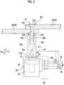
- each of the pressurizing sections 20 includes a drive unit 22 having a pressure receiving surface 21, a housing 23, and a clamp portion 22b.
- Each of the pressure receiving surfaces 21 has a pressure receiving area Sr.
- Each of the pressure receiving surfaces 21 has the individual pressure receiving area Sr according to the corresponding fastener size.
- the clamp portion 22b has a recessed portion 22a extending in a downward direction Dd.
- the clamp portion 22b grips a tip 61t of a pin 61 fitted in the recessed portion 22a, and pulls the tip 61t of the pin 61 in the downward direction Dd through driving of the drive unit 22.
- the clamp portion 22b can grip the tip 61t of the pin 61 as a split pin or the recessed portion 22a is formed into a screw shape.
- the clamp portion 22b has a pin clamp 22c as illustrated in Fig. 2 .
- the pin clamp 22c is a clamp claw, and can grip the tip 61t of the pin 61 fitted in the recessed portion 22a.
- the composite material 50 has a first composite material 51 and a second composite material 52.
- the composite material 50 is a member that configures a wing part or a main body of an aircraft.
- the first composite material 51 has a panel shape.
- the first composite material 51 has a first hole 51h penetrating a pair of panel surfaces.
- the second composite material 52 has a panel shape.
- the second composite material 52 has a second hole 52h penetrating a pair of panel surfaces.
- the fastener 60 has the pin 61 and a collar 62.
- the pin 61 has a shape extending in an axial direction from a base portion 61b toward the tip 61t.
- the collar 62 is fitted to the pin 61.
- the pin clamp 22c clamps the pin 61.
- a pressure is applied to the pressure receiving surface 21.
- the housing 23 squeezes the collar 62 fitted to the pin 61 to come into close contact with the second composite material 52 by the reaction force.
- the collar 62 caulks the pin 61.
- the fastener 60 allows the pin 61 and the collar 62 to be fitted from a first composite material 51 side and from a second composite material 52 side into the first hole 51h and the second hole 52h respectively, such that the first hole and the second hole are penetrated. Accordingly, as the first composite material 51 and the second composite material 52 are sandwiched from both sides between the pin 61 and the collar 62 and the pin 61 is fitted into the collar 62, the fastener 60 fastens the first composite material 51 and the second composite material 52 to each other.
- the pin 61 presses the first composite material 51 from above when the pin 61 is fitted into the collar 62 from above the first composite material 51 in the downward direction Dd.
- the collar 62 presses the second composite material 52 from below in an upward direction Du.
- the fastener 60 can fasten the first composite material 51 and the second composite material 52 to each other.
- the pin 61 has a broken portion at the tip 61t, and is configured such that the tip 61t of the pin 61 is torn when thrust is equal to or greater than a force required to fasten the first composite material 51 and the second composite material 52 to each other.
- the pressurizing section 20 further includes a switch 24, a supply valve 25, and a return valve 26.
- the branch end 32 of the supply system 30 is connected to the supply valve 25.
- the branch end 42 of the return system 40 is connected to the return valve 26.
- the switch 24 can switched between on and off.
- the supply valve 25 and the return valve 26 are opened.
- the supply valve 25 is opened, an oil pressurized at the predetermined pressure Pd is supplied from the branch end 32 to the pressurizing section 20, and the oil is supplied to the pressure receiving surface 21 at the predetermined pressure Pd.
- the return valve 26 is opened, the oil, which is discharged from the pressurizing section 20 with the supply of the oil to the pressure receiving surface 21, is discharged to the base end 41.
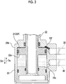
- the housing 23 includes a main body portion 23b having the abutting surface 23a.
- the main body portion 23b accommodates the drive unit 22 therein.
- the abutting surface 23a is an end surface formed on an upper end of the main body portion 23b.
- the abutting surface 23a abuts against the base portion 62b of the collar 62.
- the drive unit 22 further has a first surface 22f and a second surface 22s.
- the first surface 22f and the second surface 22s are formed in the housing 23.
- the first surface 22f functions as the pressure receiving surface 21 of the pressurizing section 20. Therefore, the first surface 22f is a surface that faces the upward direction Du and is a surface having the pressure receiving area Sr.
- the second surface 22s is a surface that forms a back surface of the first surface 22f, and faces the downward direction Dd.
- the housing 23 further has a first opening 23f and a second opening 23s.
- the first opening 23f is open toward the first surface 22f of the drive unit 22 provided inside the main body portion 23b.
- the first opening 23f is connected to the branch end 32 of the supply system 30. For this reason, an oil is injected into the first opening 23f at the predetermined pressure Pd.
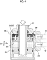
- the pressurizing section 20 has a sealed structure between the first opening 23f and the first surface 22f of the drive unit 22. For this reason, when an oil is pressurized and injected from the first opening 23f, the oil presses the first surface 22f functioning as the pressure receiving surface 21, thereby driving the drive unit 22 in the downward direction Dd as illustrated in Fig. 4 .
- the drive unit 22 is driven in the downward direction Dd by thrust corresponding to the product of an area of the pressure receiving surface 21 (the first surface 22f) and the predetermined pressure Pd.
- the second opening 23s is open toward the second surface 22s of the drive unit 22 provided inside the main body portion 23b.
- the pressurizing section 20 has a sealed structure between the second opening 23s and the second surface 22s of the drive unit 22.
- each of the pressure receiving surfaces 21 has the individual pressure receiving area Sr according to the fastener size of each of the corresponding fasteners 60.
- the term "individual” means that the unique pressure receiving area Sr is set for the fastener 60 having each fastener size, and means that the same pressure receiving area Sr is set for at least the same fastener size. Also in the case shown in Fig. 5 , a unique pressure receiving area is set for the fastener 60 having each fastener size.
- the fastener size indicates an outer diameter of the fastener.
- the fastener sizes are A, B, C, D, and E in ascending order.
- the pressure receiving surface 21 having each pressure receiving area can receive individual thrust in the downward direction Dd simply by pressurizing at the same predetermined pressure Pd as shown in Fig. 5 .
- the pump unit of the fastening system 1 of the embodiment adopts a "unified pressurizing pump unit" in which the pump units of the respective pressurizing sections 20 are unified.
- the number of pump units of the fastening system 1 is one centralized pump unit 10, and fastening operation can be performed with the number of the pump unit fixed.
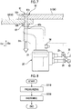
- the pressurizing section 20 is a straight type pull gun as illustrated in Fig. 2 in the embodiment, the pressurizing section may be an offset type pull gun which is a different type, just as a pressurizing section 20' illustrated in Fig. 7 in a modification example.
- the pressurizing pump 11 of the fastening system 1 pressurizes an oil at the predetermined pressure Pd (ST10: step of pressurizing). Then, the pressurized oil is supplied to the base end 31 of the supply system 30.
- the oil is supplied to the base end 31 of the supply system 30
- the oil is supplied at the predetermined pressure Pd from the base end 31 to each of the branch ends 32 of the supply system 30.
- the oil is supplied at the predetermined pressure Pd from the base end 31 to each of the pressure receiving surfaces 21, and the plurality of composite materials 50 are fastened to each other by each of the fasteners 60 (ST20: step of fastening).
- the supply valve 25 is opened as the operator turns on the switch 24 in each of the pressurizing sections 20. Accordingly, the oil supplied to each of the branch ends 32 is supplied at the predetermined pressure Pd from the base end 31 to each of the pressure receiving surfaces 21.
- the oil supplied to the pressure receiving surface 21 at the predetermined pressure Pd presses the pressure receiving surface 21 in the downward direction Dd at the predetermined pressure Pd.
- the drive unit 22 When the pressure receiving surface 21 is pressed at the predetermined pressure Pd, the drive unit 22 is driven in the downward direction Dd by thrust corresponding to the product of the area of the pressure receiving surface 21 and the predetermined pressure Pd. As shown in Fig. 5 , since the thrust of the drive unit 22 differs when the pressure receiving area Sr differs, the drive unit 22 is driven in the downward direction Dd by thrust according to the fastener size of the fastener 60, thereby pulling the tip 61t of the pin 61 in the downward direction Dd. At this time, the collar 62 abuts against the abutting surface 23a of the housing 23 and does not move in the downward direction Dd.
- the fastener 60 fastens the first composite material 51 and the second composite material 52 to each other.
- the return valve 26 is also opened.
- the return valve 26 is also opened in a case where an oil fills from the second surface 22s to the second opening 23s, the oil is discharged from the second opening 23s to the return port 12 via the return system 40 through driving of the drive unit 22 in the downward direction Dd.
- the pressurizing pump 11 may be stopped after temporarily pressurizing the inside of the supply system 30 at the predetermined pressure Pd. In this case, when a pressure in the supply system 30 declines below the set predetermined pressure Pd during the fastening operation, the pressurizing pump is operated again, and the pressure in the supply system 30 is again increased to the predetermined pressure Pd.
- the pressurizing pump 11 sets the predetermined pressure Pd to 459 kg/cm 2 (45.0 MPa) in the embodiment.
- the fastening system 1 of the embodiment can supply an oil at the predetermined pressure Pd to the pressure receiving surfaces 21 of the plurality of pressurizing sections 20 disposed at positions where the respective fasteners 60 can be fastened. Further, each of the pressure receiving surfaces 21 has the individual pressure receiving area Sr according to the corresponding fastener size, and the oil is supplied at the predetermined pressure Pd from the base end 31 of the supply system 30 to each pressure receiving surface.
- the members can be fastened to each other by the plurality of fasteners 60 with the plurality of pressurizing sections 20 and the pressurizing pump 11 fixed and disposed respectively.
- the fastening system 1 can drive the drive unit 22 of each of the pressurizing sections 20 with individual thrust while uniformly supplying an oil at the predetermined pressure Pd from the pressurizing pump 11 to the pressure receiving surface 21 of each of the pressurizing sections 20.
- subsequently another fastener 60 may be fastened in a modification example while the pressure in the supply system 30 is maintained at the predetermined pressure Pd.
- the pressurizing pump 11 sets the predetermined pressure Pd to 459 kg/cm 2 (45.0 MPa).
- the pressurizing pump 11 may maintain the predetermined pressure Pd at a set lower limit value or higher. In this case, the pressurizing pump 11 pressurizes an oil when the predetermined pressure Pd is lower than the set lower limit value.
- the pressure in the supply system 30 may be maintained within a certain range in addition to maintaining the pressure to the set lower limit value or higher.
- the pressurizing pump 11 may maintain the pressure in the supply system 30 such that the predetermined pressure Pd falls within a range of 421 to 459 kg/cm 2 (41.3 to 45.0 MPa). In this case, the pressurizing pump 11 stops after temporarily increasing the pressure in the supply system 30 to 459 kg/cm 2 .
- the pressurizing pump 11 operates again, and pressurizes the oil until the predetermined pressure Pd in the supply system 30 becomes 459 kg/cm 2 again.
- each of the pressure receiving surfaces 21 has the individual pressure receiving area Sr according to the fastener size of the corresponding fastener 60.
- the pressurizing sections 20 may have pressure receiving areas different from each other according to each fastener size.
- each of the pressure receiving surfaces 21 may be set such that the pressure receiving area Sr increases as the fastener size of the corresponding fastener 60 increases.
- the burden of the fastening operation can be reduced.
Landscapes
- Engineering & Computer Science (AREA)
- Mechanical Engineering (AREA)
- General Engineering & Computer Science (AREA)
- Manufacturing & Machinery (AREA)
- Transportation (AREA)
- Aviation & Aerospace Engineering (AREA)
- Automatic Assembly (AREA)
- Insertion Pins And Rivets (AREA)
Applications Claiming Priority (2)
| Application Number | Priority Date | Filing Date | Title |
|---|---|---|---|
| JP2018059928A JP6963527B2 (ja) | 2018-03-27 | 2018-03-27 | 締結システム及び締結方法 |
| PCT/JP2019/012108 WO2019188789A1 (fr) | 2018-03-27 | 2019-03-22 | Système de fixation et procédé de fixation |
Publications (2)
| Publication Number | Publication Date |
|---|---|
| EP3778065A1 true EP3778065A1 (fr) | 2021-02-17 |
| EP3778065A4 EP3778065A4 (fr) | 2021-12-29 |
Family
ID=68061949
Family Applications (1)
| Application Number | Title | Priority Date | Filing Date |
|---|---|---|---|
| EP19774368.5A Withdrawn EP3778065A4 (fr) | 2018-03-27 | 2019-03-22 | Système de fixation et procédé de fixation |
Country Status (4)
| Country | Link |
|---|---|
| US (1) | US11396039B2 (fr) |
| EP (1) | EP3778065A4 (fr) |
| JP (1) | JP6963527B2 (fr) |
| WO (1) | WO2019188789A1 (fr) |
Family Cites Families (5)
| Publication number | Priority date | Publication date | Assignee | Title |
|---|---|---|---|---|
| JPS48105975U (fr) * | 1972-03-10 | 1973-12-08 | ||
| JPS5119249Y2 (fr) * | 1972-04-15 | 1976-05-20 | ||
| CA1129823A (fr) | 1979-05-30 | 1982-08-17 | Huck Manufacturing Company | Outil de pose de fixations, et systeme de fixation connexe |
| KR101295258B1 (ko) * | 2013-06-14 | 2013-08-09 | (주)벽산엔지니어링 | 멀티 리벳팅 장치 |
| EP3306421B1 (fr) | 2016-10-05 | 2021-04-21 | The Swatch Group Research and Development Ltd | Montre comportant un dispositif de transmission entre un organe de commande et le mouvement |
-
2018
- 2018-03-27 JP JP2018059928A patent/JP6963527B2/ja active Active
-
2019
- 2019-03-22 WO PCT/JP2019/012108 patent/WO2019188789A1/fr not_active Ceased
- 2019-03-22 US US16/961,038 patent/US11396039B2/en active Active
- 2019-03-22 EP EP19774368.5A patent/EP3778065A4/fr not_active Withdrawn
Also Published As
| Publication number | Publication date |
|---|---|
| US20200368806A1 (en) | 2020-11-26 |
| WO2019188789A1 (fr) | 2019-10-03 |
| US11396039B2 (en) | 2022-07-26 |
| JP6963527B2 (ja) | 2021-11-10 |
| EP3778065A4 (fr) | 2021-12-29 |
| JP2019171396A (ja) | 2019-10-10 |
Similar Documents
| Publication | Publication Date | Title |
|---|---|---|
| US6725521B1 (en) | Fastening of sheet material | |
| EP2219853B1 (fr) | Procédé de renforcement d'un élément composite à fibres ainsi que tapis de vide et dispositif de fabrication d'un élément composite à fibres renforcé | |
| EP3098459B1 (fr) | Structure d'aéronef avec dispositif de fixation | |
| US20140084600A1 (en) | Emergency opening device for an aircraft door | |
| US5620287A (en) | Fastener system with controlled clamping load | |
| US20120210550A1 (en) | Hydropneumatic riveter | |
| JP2012163205A (ja) | 金属コンポーネントと複合材コンポーネントとを機械的に結合するための方法と装置 | |
| AU2014238260B2 (en) | Systems and methods for improving bolted joints | |
| EP2173539A1 (fr) | Appareil et procédé pour former des structures composites renforcées par des fibres | |
| EP3778065A1 (fr) | Système de fixation et procédé de fixation | |
| EP2655183B1 (fr) | Agencement de fixation destiné à fixer un élément d'un avion ou d'un engin spatial, dispositif de retenue adhésif d'un agencement de fixation de ce type et avion ou engin spatial présentant un agencement de fixation de ce type et/ou dispositif de retenue adhésif de ce type | |
| DE102014204087A1 (de) | Halter zur Anbindung eines Bauteils an eine Komponente eines Luft- oder Raumfahrzeugs, Anordnung, Luft- oder Raumfahrzeug, sowie Verfahren | |
| CN107965218B (zh) | 一种舱门快卸锁机构 | |
| DE102007055460A1 (de) | Ventilblock | |
| RU2735767C2 (ru) | Быстроразъемный установочный инструмент для элемента, подлежащего обжиму | |
| EP2428352A1 (fr) | Assemblage à vide pour excercer une pression sur un composant lors de sa fabrication et procédé de fabrication d'un composant | |
| WO2018020028A1 (fr) | Dispositif de préhension et de transport de substrats | |
| CN104703723B (zh) | 用于提供偏斜补偿的c型框架结构和相关方法以及机器人系统 | |
| US20240342886A1 (en) | Systems, Apparatuses, and Methods for Installing a Temporary Fastener in an Assembly | |
| EP3508738B1 (fr) | Dispositif de blocage | |
| JP2003524126A (ja) | リベット、リベットの製造方法、及びリベットの使用方法 | |
| CN110753803A (zh) | 用于将张紧元件固定在单元上的固定单元 | |
| JP2023118064A (ja) | 締結構造を得るために第2の構造体に対して第1の構造体をクランプするための構造ブラインドスリーブ及び関連するシステム及び方法 | |
| CN102615234B (zh) | 一种铆钉压紧装置 | |
| KR20180031843A (ko) | 피복선 삽입형 플렉시블 튜브와 그립 조립장치 |
Legal Events
| Date | Code | Title | Description |
|---|---|---|---|
| STAA | Information on the status of an ep patent application or granted ep patent |
Free format text: STATUS: THE INTERNATIONAL PUBLICATION HAS BEEN MADE |
|
| PUAI | Public reference made under article 153(3) epc to a published international application that has entered the european phase |
Free format text: ORIGINAL CODE: 0009012 |
|
| STAA | Information on the status of an ep patent application or granted ep patent |
Free format text: STATUS: REQUEST FOR EXAMINATION WAS MADE |
|
| 17P | Request for examination filed |
Effective date: 20200708 |
|
| AK | Designated contracting states |
Kind code of ref document: A1 Designated state(s): AL AT BE BG CH CY CZ DE DK EE ES FI FR GB GR HR HU IE IS IT LI LT LU LV MC MK MT NL NO PL PT RO RS SE SI SK SM TR |
|
| AX | Request for extension of the european patent |
Extension state: BA ME |
|
| DAV | Request for validation of the european patent (deleted) | ||
| DAX | Request for extension of the european patent (deleted) | ||
| A4 | Supplementary search report drawn up and despatched |
Effective date: 20211201 |
|
| RIC1 | Information provided on ipc code assigned before grant |
Ipc: B21J 15/20 20060101ALI20211125BHEP Ipc: B21J 15/14 20060101ALI20211125BHEP Ipc: B21J 15/16 20060101ALI20211125BHEP Ipc: B21J 15/00 20060101ALI20211125BHEP Ipc: B21J 15/02 20060101AFI20211125BHEP |
|
| GRAP | Despatch of communication of intention to grant a patent |
Free format text: ORIGINAL CODE: EPIDOSNIGR1 |
|
| STAA | Information on the status of an ep patent application or granted ep patent |
Free format text: STATUS: GRANT OF PATENT IS INTENDED |
|
| RIC1 | Information provided on ipc code assigned before grant |
Ipc: B21J 15/20 20060101ALI20220920BHEP Ipc: B21J 15/14 20060101ALI20220920BHEP Ipc: B21J 15/16 20060101ALI20220920BHEP Ipc: B21J 15/00 20060101ALI20220920BHEP Ipc: B21J 15/02 20060101AFI20220920BHEP |
|
| INTG | Intention to grant announced |
Effective date: 20221014 |
|
| STAA | Information on the status of an ep patent application or granted ep patent |
Free format text: STATUS: THE APPLICATION IS DEEMED TO BE WITHDRAWN |
|
| 18D | Application deemed to be withdrawn |
Effective date: 20230225 |