EP3778367A1 - Automatisches verriegelungs-/entriegelungssystem für durch pedalhebel betätigte zugsysteme - Google Patents
Automatisches verriegelungs-/entriegelungssystem für durch pedalhebel betätigte zugsysteme Download PDFInfo
- Publication number
- EP3778367A1 EP3778367A1 EP18932061.7A EP18932061A EP3778367A1 EP 3778367 A1 EP3778367 A1 EP 3778367A1 EP 18932061 A EP18932061 A EP 18932061A EP 3778367 A1 EP3778367 A1 EP 3778367A1
- Authority
- EP
- European Patent Office
- Prior art keywords
- pedal
- lever
- previous
- accordance
- blocking
- Prior art date
- Legal status (The legal status is an assumption and is not a legal conclusion. Google has not performed a legal analysis and makes no representation as to the accuracy of the status listed.)
- Withdrawn
Links
- 230000000903 blocking effect Effects 0.000 claims abstract description 64
- 230000008878 coupling Effects 0.000 claims abstract description 36
- 238000010168 coupling process Methods 0.000 claims abstract description 36
- 238000005859 coupling reaction Methods 0.000 claims abstract description 36
- 230000004913 activation Effects 0.000 claims abstract description 16
- 239000004020 conductor Substances 0.000 claims description 14
- 230000003213 activating effect Effects 0.000 claims description 9
- 230000001788 irregular Effects 0.000 claims description 2
- 230000033001 locomotion Effects 0.000 description 5
- 230000008859 change Effects 0.000 description 3
- 238000010586 diagram Methods 0.000 description 2
- 230000007246 mechanism Effects 0.000 description 2
- 230000001360 synchronised effect Effects 0.000 description 2
- 229910000838 Al alloy Inorganic materials 0.000 description 1
- 230000000712 assembly Effects 0.000 description 1
- 238000000429 assembly Methods 0.000 description 1
- 230000005540 biological transmission Effects 0.000 description 1
- 230000002708 enhancing effect Effects 0.000 description 1
- 239000000463 material Substances 0.000 description 1
- 238000009987 spinning Methods 0.000 description 1
- 238000002560 therapeutic procedure Methods 0.000 description 1
- 230000008719 thickening Effects 0.000 description 1
Images






Classifications
-
- B—PERFORMING OPERATIONS; TRANSPORTING
- B62—LAND VEHICLES FOR TRAVELLING OTHERWISE THAN ON RAILS
- B62M—RIDER PROPULSION OF WHEELED VEHICLES OR SLEDGES; POWERED PROPULSION OF SLEDGES OR SINGLE-TRACK CYCLES; TRANSMISSIONS SPECIALLY ADAPTED FOR SUCH VEHICLES
- B62M1/00—Rider propulsion of wheeled vehicles
- B62M1/24—Rider propulsion of wheeled vehicles with reciprocating levers, e.g. foot levers
-
- B—PERFORMING OPERATIONS; TRANSPORTING
- B62—LAND VEHICLES FOR TRAVELLING OTHERWISE THAN ON RAILS
- B62M—RIDER PROPULSION OF WHEELED VEHICLES OR SLEDGES; POWERED PROPULSION OF SLEDGES OR SINGLE-TRACK CYCLES; TRANSMISSIONS SPECIALLY ADAPTED FOR SUCH VEHICLES
- B62M1/00—Rider propulsion of wheeled vehicles
- B62M1/36—Rider propulsion of wheeled vehicles with rotary cranks, e.g. with pedal cranks
-
- B—PERFORMING OPERATIONS; TRANSPORTING
- B62—LAND VEHICLES FOR TRAVELLING OTHERWISE THAN ON RAILS
- B62M—RIDER PROPULSION OF WHEELED VEHICLES OR SLEDGES; POWERED PROPULSION OF SLEDGES OR SINGLE-TRACK CYCLES; TRANSMISSIONS SPECIALLY ADAPTED FOR SUCH VEHICLES
- B62M3/00—Construction of cranks operated by hand or foot
-
- B—PERFORMING OPERATIONS; TRANSPORTING
- B62—LAND VEHICLES FOR TRAVELLING OTHERWISE THAN ON RAILS
- B62M—RIDER PROPULSION OF WHEELED VEHICLES OR SLEDGES; POWERED PROPULSION OF SLEDGES OR SINGLE-TRACK CYCLES; TRANSMISSIONS SPECIALLY ADAPTED FOR SUCH VEHICLES
- B62M3/00—Construction of cranks operated by hand or foot
- B62M3/08—Pedals
Definitions
- This invention is related to the Mechanical, Electrical and Electronic technical fields since it provides an automatic locking/unlocking system and a pedal lever for traction systems actuated by pedal levers.
- cranks for use in machines propelled by humans, such as bicycles and crank-actuated exercise machines, and refers specifically to a crank equipped with a unidirectional clutch and a coupler that can arrange to be coupled so as to prevent the shaft to rotate in the opposite direction to the axis of the crank.
- crank set that can be used to propel a crankshaft in two modes.
- a unidirectional shaft In the first mode, a unidirectional shaft must allow the free rotation of the crank with respect to the crankshaft, yet couple the crank to the crankshaft manually when the crank moves in an opposite rotation direction.
- the crank In the second mode, the crank must be vigorously coupled to the axis in order to propel the axis in any direction, and the mechanism must be able to move between the two modes in a simple and swift manner.
- crank in document US7607370 (B2) includes an associated mechanism through which a crank arm can be attached drivingly to a crankshaft and can be used in a first mode to propel the crankshaft in one direction of rotation, but allowing free rotation on the crankshaft in an opposite rotational direction.
- a coupler is carried movably on an inner end of the crank arm and is movable between an engaged or coupled position and a disengaged or uncoupled condition. In one embodiment engagement of the coupler results in the crank arm being held in a predetermined angular position with respect to the crankshaft or a hub portion of the crank attached to the crankshaft.
- crank assembly 10 which includes a crank arm 12, of a suitable material such as an aluminum alloy, that has a radially inner end 14 adapted to be attached to an end of a crankshaft as will be described in more detail presently, and an outer end 16.
- the crank arm 12 as shown herein is equipped with an array 18 of parallel grooves and ridges and a set of threaded bores 20, to accept adjustable attachment of a pedal at a selected location to provide a desired effective crank arm length, but it will be apparent that the crank could also be manufactured in a selected length with a conventional threaded bore (not shown) to accept a pedal or handle, depending upon the use to which the crank assembly 10 is intended to be put.
- FIG. 2 illustrates a pair of crank assemblies 10L and 10R, equipped with their respective pedals 22, and each crank assembly 10L, 10R is attached to a respective one of a pair of opposite ends of a power input shaft, such as a crank shaft 30, shown in simplified form, without the supporting bearings that would be necessary, such as the bearings in the bottom bracket of a bicycle or an exercise machine.
- a power input shaft such as a crank shaft 30, shown in simplified form
- crankshaft enhanced by a freewheel; in which the crankshaft, according to the invention, has at least a fixed means that permits traveling with a free wheel depending on the rotation direction or coupling a torsion movement to both rotation directions.
- the crankshaft, according to the invention can be used as a pedal crankshaft in bicycles and other forms of locomotion or training or exercise machines built in a similar manner.
- the area of application is not limited to this. It can also be used, for example, in manually activated equipment in which a switch is desired between an enhanced change of phase or synchronous movement in phase and gear with a freewheel.
- FIGs 1 and 2 of document WO03101815 illustrate a first embodiment in which an adapter 1 with a receiving opening 10 of an axis of a crankshaft of a bicycle or another device.
- the receiving opening 10 is used for a fixed and rotatory connection of adapter 1 to the axis of the crankshaft and as a consequence of this it generally has a square transverse section.
- the adapter has a cylindrical main body which is preferably equipped with a boss on the side of the axis of the crankshaft.
- a single direction or freewheel coupling is mounted to adapter 1. This coupling is fixed to an arm 3 of the crankshaft in a rotatory manner.
- arm 3 of the crankshaft on one end has a 3" cylindrical housing which accommodates sleeve 2 of the freewheel. If the crankshaft is used as a pedal crankshaft, a pedal can be connected to the other end of arm 3.
- the 3" housing, sleeve 2 of the freewheel and adapter 1 are preferably connected between them and in relation to the axis of the crankshaft by way of thread joints.
- Adapter 1 and sleeve 2 of the freewheel form a freewheel coupling.
- a rotation of arm 3 of the crankshaft in a first rotation direction transmits a torsion moment to the axis of the crankshaft and in this way also to the bicycle chain or other activation element.
- arm 3 of the crankshaft works freely.
- the moment of torsion produced decouples from adapter 1 and, as a consequence, from the axis of the crankshaft.
- a synchronized phase gear change of the two pedals is only possible if the cyclist exerts on each individual pedal a uniform force through time.
- the pedals can also rotate in phase, increasing training and the available therapy options.
- there is at least one means of fastening which permits the optional change of this single direction coupling into a double-direction coupling, since the moment of torsion is transmitted to the axis of the crankshaft in both rotation directions.
- the means of fastening is a blocking pin 6 on a spring that passes through an opening of the 3" housing, which can be connected to the receiving opening 40 of a disc-cap 4.
- the disc-cap 4 is placed in a rotationally fixed manner on the adapter 1 or on another element that is rotationally fixed to the axis of the crankshaft.
- Blocking pin 6 is activated through a rotating ring 5 placed concentrically around disc-cap 4 so that it may rotate around it.
- an elastic band 8 placed over the surface of the inner ring of rotating ring 5 projects into the interior of the said cavity.
- Elastic band 8 is preferably fastened to rotating ring 5 through a 10' rivet.
- the blocking pin 6, introduced into the 3" housing is pushed in the direction of receiving opening 40 of the disc-cap 4 against the force of a return spring 7, which results in a blocking connection between arm 3 and the axis of the crankshaft.
- the said ring preferably has a block pin 9 that projects toward the cavity in a position adjacent to elastic band 8 and supports against blocking pin 6 in its blocked state.
- Blocking pin 6 acts as driving force of disc-cap 4, resulting in torque being transmitted from arm 3 of the crankshaft to the axis of the crankshaft, even when sleeve 2 is in motion with the freewheel. If rotating ring 5 rotates in the opposite direction, blocking pin 6 slides outward along elastic band 8 and releases disc-cap 4 once more. In this state, the transmission of the torsion moment takes place immediately and in a single rotation direction.
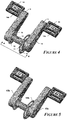
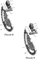
- the locking/unlocking system for traction systems actuated by pedal levers proposed by this invention is composed of: A blocking element (1) which has a coupling section (1a) and a push and retraction section (1b), which is configured to interact with some element that pushes and/or pulls the blocking element (1).
- the said configuration of the push and retraction section (1b) can be: a zipper (20); a non-skid area; a thread; a perforation; a tongue-and-groove section; a magnetic section; or a section that is thinner or thicker than the coupling section (1a), to which a spring is added externally (2) and/or directly through the use of an automatic activation device (3).
- a mode of the system in question is when the blocking element (1) includes a fastening element (21) located on the free end of the push and retraction section (1b) when the said blocking element (1) is directly connected to the automatic activating device (3).
- the fastening element (21) can be a block, a pin, a ring, a thickening, a fold, a boss, a protuberance, a combination of some of the above, etc.
- An embodiment of the system in accordance with the present invention is when the blocking element (1) is: a bolt, a screw, a piston, an axle, a bar, among others.
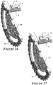
- the said locking/unlocking system for traction systems actuated by pedal levers must also include a receiving element (10) which has at least a coupling means (10a) for coupling to the coupling section (1a) of the blocking element (1), in which the said receiving element (10) is concentrically fixed to the rotating axis (8) of a traction system actuated by pedal levers.
- the receiving element (10) may be: a disc, a polygon, a preferably flat piece with an irregular perimeter, or a star, and its coupling means can be: a perforation (10a), a groove, a cleft and/or a boss, to mention some examples.
- a mode of the blocking/unblocking system is that it also includes a conduction element (11) which can be a star with its chain; a pulley with its belt, cable, rope or band; or a cogwheel with its cog.
- a conduction element (11) which can be a star with its chain; a pulley with its belt, cable, rope or band; or a cogwheel with its cog.
- the locking/unlocking system has an automatic activating means (3) that moves the blocking element (1) through its pull and retraction section (1b), in order to couple it and decouple it through the coupling means (10a) of the receiving element (10).
- a preferable embodiment of the locking/unlocking system is when the electronic actuator is a motor, servomotor or stepper motor.
- Another preferable mode of the locking/unlocking system is when the electromagnetic actuator is a solenoid.
- the locking/unlocking system in question also includes at least a control means (16) for controlling the automatic activating device (3); in which the control means (16) is selected from the following group: electric and/or electronic circuits; integrated circuits; position limiting means, and/or sensors.
- the locking/unlocking system also has at least one switch (15a, 15b) for turning on or off at least one control means (16); the said switch (15a, 15b) can be either wired or wireless and is located at a place that is easily accessed and manipulated by the user.
- the said locking/unlocking system includes at least a power source (17) for powering at least the control means (16) and/or the automatic activation device (3).
- the power source (17) is selected from the following group: batteries, power units, solar cells, energy generators and/or a combination of the above.
- An additional mode of the locking/unlocking system is when it also includes connecting means that connect the blocking element (1) to the automatic activation device (3); in which the said connecting means make direct contact with the push and/or retraction section (1b) of the blocking element (1) and may be: clogs (19), a lever (5) fastened to the end of the push and/or retraction section (1b) of the blocking element (1); or a combination of the said lever (5) with a cam (4) fixed to the end of the axis of the automatic activation device (3), so as to push and/or retract the lever (5) which in turn pushes and/or retracts the blocking element (1).
- a further embodiment of the locking/unlocking system in question is that it can optionally include, at least: a sound, light and/or vibration emitter; an inclination measuring device; and/or a means of transmitting information, either wired or wireless, in order to warn the user of certain conditions of the locking/unlocking system, for example: if the blocking element (1) is in a blocking or unblocking position; when the traction system actuated by pedal levers has a certain angle of inclination and/or when the pedal levers (9) have a certain angle of inclination.
- the present invention also contemplates a pedal lever (9), for traction systems actuated by pedal levers, which includes: a locking/unlocking system, as proposed by the present invention. Therefore, the said pedal lever (9) has a cavity (9a) which houses the locking/unlocking system, except for the receiving element (10) and the conductor element (11); a first perforation (22) through which the coupling section (1a) exits from the blocking element (1), so as to couple with the coupling means (10a) of the receiving element (10); a second perforation (24) placed on the end where the first perforation is located (22), so as to connect to a traction system actuated by pedal levers; a third perforation (23) on the opposite end of the second perforation (24), which connects to a pedal (14).
- a cavity (9a) which houses the locking/unlocking system, except for the receiving element (10) and the conductor element (11); a first perforation (22) through which the coupling section (1a) exits from the blocking
- the pedal lever can include a fastening means (14a) located on its pedal (14), so as to fasten the pedal (14) to the foot of the user, and the fastening means (14a) can be: staples, magnets, hoops, loops, girdles, Velcro and clasps.
- a mode of the pedal lever (9) is when it also includes a freewheel (6) equipped with ball and/or plain bearings, concentrically placed within the second perforation (24).
- pedal lever (9) Another mode of the said pedal lever (9) is when it includes a freewheel adapter (7), concentrically placed within the freewheel (6).
- lever (9) in question is when it includes at least one cap (18) that covers, at least, the cavity (9a), once the part of the locking/unlocking system that has to be on the interior is effectively inside.
- another object of the present invention is a traction system actuated by pedal levers, which has a central axis (8) mounted on two wheels or bearings (13), that in turn are located inside a tubular shell (12);
- the said traction system includes: a pedal lever (9) like the one described in the present invention, on each of the two ends of the central axis (8), which is introduced and fastened to the freewheel adapter (7), or directly to the freewheel (6), of the said pedal lever (9); a receiving element (10) mounted concentrically on each of the ends of the central axis (8), between the pedal lever (9) and the tubular shell (12), in which the coupling means (10a) of each receiving element (10) are aligned at 180° between them; and a conductor element (11) located on one of the ends of the central axis (8).
- a variation of the traction system actuated by pedal levers, of the present invention is when only one of the switches, either wired or wireless, of the two blocking/unblocking systems of the said traction system, turns the two means of control (16) on and/or off. It is therefore possible to have a mode in which one of the two blocking/unblocking systems lacks a switch, either wired or wireless; or in case one of the switches, either wired or wireless, should fail, the automatic functioning of the locking/unlocking system would not be affected.
- Another mode of the traction system actuated by pedal levers, of the present invention is when only one of the means of control (16), of the two blocking/unblocking systems of the said traction system, controls the two automatic activation means (3).
- One of the blocking/unblocking systems lacks a means of control (16); or in case one of the means of control (16) should fail, the automatic functioning of the locking/unlocking system would not be affected.
- a mode of the traction system in question is when the conductor element (11) is united to one of the receiving elements (10).
- a preferable embodiment of the said traction system is when the receiving element (10) and the conductor element (11) are part of a single piece.
- Another additional mode of the traction system of the present invention is when the switch (15a, 15b), of the locking/unlocking system, is on the exterior lateral face, and/or the upper and/or lower face of the pedal lever (9); and/or mounted on a handle (not illustrated) of the traction system actuated by pedal levers.
- the handle can be extensible and/or retractable, with the purpose of enhancing the posture of the user, when both blocking/unblocking systems are in an unblocking position.
- the switch is activated (15a or 15b) in order to rotate the cam once again (4) until a second specific position, which prevents the said cam (4) from continuing to push the lever (5), and through the spring (2) pushes the blocking element (1) outside the pedal lever (9), coupling in this way the locking/unlocking system once again to its respective receiving element (10), thus blocking the axis (8).
- each locking/unlocking system When each locking/unlocking system is coupled with its respective receiving element (10), it means that the blocking element (1) is out of the pedal lever (9) and coupled with its respective receiving element (10) by way of a coupling means (10a), such as a perforation located on the said receiving element (10), considering that the coupling means (10a) of a receiving element (10) must be located preferably at 180° in relation to the coupling means (10a) of the other receiving element (10), thus ensuring that when the locking/unlocking system of each pedal lever (9) is coupled, each pedal lever (9) is positioned at 180° from each other; so that the force exerted on the pedal (14) is transmitted through the pedal lever (9) until the blocking element (1), which in turn transmits the force to the receiving element (10), and it in turns transmits the force to the central axis (8), at the same time that the receiving element (10) which is assembled together with the conductor element (11) also transmits that force to the said conductor element (11).
- Some of the advantages of the locking/unlocking system of the present invention consists in the fact that it is provided with, at least: a switch, either wired or wireless, a power source (17), a means of control (16) and an automatic activating means (3) for activating the automatic blocking and unblocking of each pedal lever (9), without the user having to make a physical effort for bringing about the blocking and unblocking.
- traction systems actuated by pedal levers can be the traction systems for the following machines or devices: common bicycles, mountain bicycles, racing bicycles, spinning bicycles, tricycles, quadricycles, pedalos or paddle boats, to mention a few examples.
- the blocking means (1), of the locking/unlocking system can also be mechanically moved with the hand and/or foot of the user, which is important in case of failure of the automatic system.
Landscapes
- Engineering & Computer Science (AREA)
- Chemical & Material Sciences (AREA)
- Combustion & Propulsion (AREA)
- Transportation (AREA)
- Mechanical Engineering (AREA)
- Lock And Its Accessories (AREA)
- Arrangement And Mounting Of Devices That Control Transmission Of Motive Force (AREA)
- Mechanical Control Devices (AREA)
Applications Claiming Priority (2)
| Application Number | Priority Date | Filing Date | Title |
|---|---|---|---|
| MX2018010336A MX390875B (es) | 2018-08-27 | 2018-08-27 | Sistema de bloqueo/desbloqueo automatizado para sistemas de tracción accionados por palancas de pedaleo |
| PCT/MX2018/000077 WO2020046097A1 (es) | 2018-08-27 | 2018-08-27 | Sistema de bloqueo/desbloqueo automatizado para sistemas de tracción accionados por palancas de pedaleo |
Publications (2)
| Publication Number | Publication Date |
|---|---|
| EP3778367A1 true EP3778367A1 (de) | 2021-02-17 |
| EP3778367A4 EP3778367A4 (de) | 2021-10-27 |
Family
ID=69642765
Family Applications (1)
| Application Number | Title | Priority Date | Filing Date |
|---|---|---|---|
| EP18932061.7A Withdrawn EP3778367A4 (de) | 2018-08-27 | 2018-08-27 | Automatisches verriegelungs-/entriegelungssystem für durch pedalhebel betätigte zugsysteme |
Country Status (5)
| Country | Link |
|---|---|
| US (1) | US11634193B2 (de) |
| EP (1) | EP3778367A4 (de) |
| CA (1) | CA3097687A1 (de) |
| MX (1) | MX390875B (de) |
| WO (1) | WO2020046097A1 (de) |
Cited By (1)
| Publication number | Priority date | Publication date | Assignee | Title |
|---|---|---|---|---|
| DE102021110754A1 (de) | 2021-04-27 | 2022-10-27 | MG Components GmbH & Co. KG | Blockiervorrichtung für die Antriebseinheit eines E-Bikes mit Mittelmotor |
Families Citing this family (4)
| Publication number | Priority date | Publication date | Assignee | Title |
|---|---|---|---|---|
| IT202100001331A1 (it) * | 2021-01-25 | 2022-07-25 | Ochain S R L | Bicicletta con sospensione posteriore e relativo dispositivo di compensazione dell'escursione di detta sospensione |
| CN114954768B (zh) * | 2022-07-15 | 2023-12-05 | 淮阴工学院 | 一种脚踏式电动车防滑脚踏装置 |
| WO2024018493A1 (en) * | 2022-07-21 | 2024-01-25 | Ochain S.R.L. | Bicycle with rear suspension and related compensating device of the travel of said suspension |
| DE102023126780A1 (de) * | 2023-10-02 | 2025-04-03 | Sportstech Brands Holding Gmbh | Fahrrad-Heimtrainer mit anpassbarem Kurbelsystem |
Family Cites Families (17)
| Publication number | Priority date | Publication date | Assignee | Title |
|---|---|---|---|---|
| US4650049A (en) | 1985-07-15 | 1987-03-17 | Stephens Charles W | Cycle hub convertible between coaster brake and freewheeling operation |
| US6213910B1 (en) * | 1996-12-20 | 2001-04-10 | Shimano, Inc. | Bicycle antitheft control device, shifting device and shifting system |
| JP2989173B1 (ja) * | 1998-07-29 | 1999-12-13 | 三桜工業株式会社 | 二輪車等のペダル位置切換え装置 |
| DE60301883T2 (de) | 2002-06-03 | 2006-07-27 | Urs Tanner | Kurbel mit freilauf |
| EP1728712A1 (de) * | 2005-06-01 | 2006-12-06 | AUMAT Maschinenbau GmbH | Tretlager für Fahrräder |
| CN100400371C (zh) * | 2005-06-08 | 2008-07-09 | 季莹 | 助力自行车踏板 |
| US7607370B2 (en) | 2005-08-16 | 2009-10-27 | Franklin J. Day | Crank with clutch and coupler |
| CN102066188A (zh) * | 2008-05-09 | 2011-05-18 | 科兰克罗科有限公司 | 自行车曲柄锁具 |
| US20100167881A1 (en) | 2008-12-31 | 2010-07-01 | Day Franklin J | Crank mechanism and bicycle incorporating same |
| JP2011025876A (ja) * | 2009-07-29 | 2011-02-10 | Alps Electric Co Ltd | 自転車 |
| AT516330B1 (de) * | 2014-09-01 | 2016-06-15 | Gregor Schuster | Ansteuerung eines Getriebes mit segmentierten Rädern mittels elektrischer Stellelemente |
| CN204264398U (zh) * | 2014-12-12 | 2015-04-15 | 江苏爱玛车业科技有限公司 | 一种多功能脚蹬 |
| DE102016001286A1 (de) | 2015-02-12 | 2016-08-18 | Martin Kraiss | Fahrrad oder Heimtrainer mit Arm- und oder Beinantrieb |
| FR3046985A1 (fr) * | 2016-01-22 | 2017-07-28 | Hassnae Lahjou | Velo a composant electrique |
| TWM537062U (zh) * | 2016-08-09 | 2017-02-21 | Vivasports Co Ltd | 健身或腳踏車用之傳動裝置 |
| CN108482533B (zh) | 2018-05-23 | 2024-12-10 | 李外桥 | 一种共享单车用牙盘锁车装置及其使用方法 |
| KR102915184B1 (ko) * | 2020-10-23 | 2026-01-20 | 현대자동차주식회사 | 전기자전거 |
-
2018
- 2018-08-27 CA CA3097687A patent/CA3097687A1/en active Pending
- 2018-08-27 WO PCT/MX2018/000077 patent/WO2020046097A1/es not_active Ceased
- 2018-08-27 EP EP18932061.7A patent/EP3778367A4/de not_active Withdrawn
- 2018-08-27 MX MX2018010336A patent/MX390875B/es unknown
- 2018-08-27 US US17/052,202 patent/US11634193B2/en active Active
Cited By (2)
| Publication number | Priority date | Publication date | Assignee | Title |
|---|---|---|---|---|
| DE102021110754A1 (de) | 2021-04-27 | 2022-10-27 | MG Components GmbH & Co. KG | Blockiervorrichtung für die Antriebseinheit eines E-Bikes mit Mittelmotor |
| DE102021110754B4 (de) | 2021-04-27 | 2024-06-13 | MG Components GmbH & Co. KG | Antriebseinheit eines E-Bikes mit Mittelmotor, aufweisend eine Blockiervorrichtung |
Also Published As
| Publication number | Publication date |
|---|---|
| US20210362804A1 (en) | 2021-11-25 |
| WO2020046097A1 (es) | 2020-03-05 |
| CA3097687A1 (en) | 2020-03-05 |
| EP3778367A4 (de) | 2021-10-27 |
| MX2018010336A (es) | 2020-02-28 |
| US11634193B2 (en) | 2023-04-25 |
| MX390875B (es) | 2025-03-21 |
Similar Documents
| Publication | Publication Date | Title |
|---|---|---|
| US11634193B2 (en) | Automatic locking/unlocking system for traction systems, actuated by pedal levers | |
| US10137954B2 (en) | Integrated electric bicycle drive system | |
| US7207584B2 (en) | Motorized bicycle drive system using a standard freewheel and left-crank drive | |
| US8353228B2 (en) | Lockable or releasable bicycle with bidirectional input and one-way output | |
| US7832753B2 (en) | Gear shift bar at a wheel for a vehicle | |
| US10137961B2 (en) | Bicycle drive unit | |
| US10858059B2 (en) | Combined torque, direction, and cadence sensing system for electric bicycles | |
| US20110108373A1 (en) | Bicycle crank lock | |
| MX2014014824A (es) | Sistema de resistencia hibrido. | |
| US10822053B2 (en) | Bicycle internal transmission hub | |
| US10822052B2 (en) | Bicycle shifting device and bicycle internal transmission hub | |
| TW202408872A (zh) | 用於自行車之具備致動裝置之底托架變速箱 | |
| EP1509440B1 (de) | Kurbel mit freilauf | |
| KR200414309Y1 (ko) | 개선된 다기능 페달 운동 자전거 | |
| KR20140133796A (ko) | 왕복동식 페달을 갖는 자전거 | |
| US20060183580A1 (en) | Multifunctional pedaling motion bicycle | |
| US20070114086A1 (en) | Vehicle propulsion system and vehicles adapted to include propulsion system | |
| KR20140033535A (ko) | 왕복동식 페달을 갖는 자전거 | |
| EP3205568B1 (de) | Getriebeanordnung ohne tretlager für velozipede | |
| KR20130078846A (ko) | 전기 자전거의 구동장치 | |
| TW202021862A (zh) | 傳動系統 | |
| KR200400752Y1 (ko) | 전,후륜구동 자전차 | |
| WO2001094194A1 (fr) | Entrainement manuel supplementaire pour velos | |
| TW202408873A (zh) | 用於自行車之具備高強度齒輪之底托架變速箱 | |
| SU1323456A1 (ru) | Устройство дл приведени в действие транспортных средств мускульной силой человека |
Legal Events
| Date | Code | Title | Description |
|---|---|---|---|
| STAA | Information on the status of an ep patent application or granted ep patent |
Free format text: STATUS: THE INTERNATIONAL PUBLICATION HAS BEEN MADE |
|
| PUAI | Public reference made under article 153(3) epc to a published international application that has entered the european phase |
Free format text: ORIGINAL CODE: 0009012 |
|
| STAA | Information on the status of an ep patent application or granted ep patent |
Free format text: STATUS: REQUEST FOR EXAMINATION WAS MADE |
|
| 17P | Request for examination filed |
Effective date: 20201028 |
|
| AK | Designated contracting states |
Kind code of ref document: A1 Designated state(s): AL AT BE BG CH CY CZ DE DK EE ES FI FR GB GR HR HU IE IS IT LI LT LU LV MC MK MT NL NO PL PT RO RS SE SI SK SM TR |
|
| AX | Request for extension of the european patent |
Extension state: BA ME |
|
| A4 | Supplementary search report drawn up and despatched |
Effective date: 20210924 |
|
| RIC1 | Information provided on ipc code assigned before grant |
Ipc: B62M 1/36 20130101ALI20210920BHEP Ipc: B62M 3/00 20060101ALI20210920BHEP Ipc: B62M 1/24 20130101AFI20210920BHEP |
|
| DAV | Request for validation of the european patent (deleted) | ||
| DAX | Request for extension of the european patent (deleted) | ||
| GRAP | Despatch of communication of intention to grant a patent |
Free format text: ORIGINAL CODE: EPIDOSNIGR1 |
|
| STAA | Information on the status of an ep patent application or granted ep patent |
Free format text: STATUS: GRANT OF PATENT IS INTENDED |
|
| INTG | Intention to grant announced |
Effective date: 20230704 |
|
| GRAJ | Information related to disapproval of communication of intention to grant by the applicant or resumption of examination proceedings by the epo deleted |
Free format text: ORIGINAL CODE: EPIDOSDIGR1 |
|
| STAA | Information on the status of an ep patent application or granted ep patent |
Free format text: STATUS: REQUEST FOR EXAMINATION WAS MADE |
|
| GRAP | Despatch of communication of intention to grant a patent |
Free format text: ORIGINAL CODE: EPIDOSNIGR1 |
|
| STAA | Information on the status of an ep patent application or granted ep patent |
Free format text: STATUS: GRANT OF PATENT IS INTENDED |
|
| INTC | Intention to grant announced (deleted) | ||
| INTG | Intention to grant announced |
Effective date: 20231124 |
|
| STAA | Information on the status of an ep patent application or granted ep patent |
Free format text: STATUS: THE APPLICATION IS DEEMED TO BE WITHDRAWN |
|
| 18D | Application deemed to be withdrawn |
Effective date: 20240326 |