EP3779018A1 - Dispositif de préhension de bord et dispositif d'expansion automatique de tissu équipé de celui-ci - Google Patents
Dispositif de préhension de bord et dispositif d'expansion automatique de tissu équipé de celui-ci Download PDFInfo
- Publication number
- EP3779018A1 EP3779018A1 EP19785400.3A EP19785400A EP3779018A1 EP 3779018 A1 EP3779018 A1 EP 3779018A1 EP 19785400 A EP19785400 A EP 19785400A EP 3779018 A1 EP3779018 A1 EP 3779018A1
- Authority
- EP
- European Patent Office
- Prior art keywords
- cloth
- edge
- clamping
- conveyor
- holding device
- Prior art date
- Legal status (The legal status is an assumption and is not a legal conclusion. Google has not performed a legal analysis and makes no representation as to the accuracy of the status listed.)
- Granted
Links
Images










Classifications
-
- D—TEXTILES; PAPER
- D06—TREATMENT OF TEXTILES OR THE LIKE; LAUNDERING; FLEXIBLE MATERIALS NOT OTHERWISE PROVIDED FOR
- D06C—FINISHING, DRESSING, TENTERING OR STRETCHING TEXTILE FABRICS
- D06C3/00—Stretching, tentering or spreading textile fabrics; Producing elasticity in textile fabrics
- D06C3/02—Stretching, tentering or spreading textile fabrics; Producing elasticity in textile fabrics by endless chain or like apparatus
-
- D—TEXTILES; PAPER
- D06—TREATMENT OF TEXTILES OR THE LIKE; LAUNDERING; FLEXIBLE MATERIALS NOT OTHERWISE PROVIDED FOR
- D06F—LAUNDERING, DRYING, IRONING, PRESSING OR FOLDING TEXTILE ARTICLES
- D06F67/00—Details of ironing machines provided for in groups D06F61/00, D06F63/00, or D06F65/00
- D06F67/04—Arrangements for feeding or spreading the linen
-
- D—TEXTILES; PAPER
- D06—TREATMENT OF TEXTILES OR THE LIKE; LAUNDERING; FLEXIBLE MATERIALS NOT OTHERWISE PROVIDED FOR
- D06F—LAUNDERING, DRYING, IRONING, PRESSING OR FOLDING TEXTILE ARTICLES
- D06F89/00—Apparatus for folding textile articles with or without stapling
-
- D—TEXTILES; PAPER
- D06—TREATMENT OF TEXTILES OR THE LIKE; LAUNDERING; FLEXIBLE MATERIALS NOT OTHERWISE PROVIDED FOR
- D06F—LAUNDERING, DRYING, IRONING, PRESSING OR FOLDING TEXTILE ARTICLES
- D06F95/00—Laundry systems or arrangements of apparatus or machines; Mobile laundries
Definitions
- An edge locating conveyor 8 delivers the cloth Y having been released from the two-position holding device.
- the two-position holding device releases the two held portions at different timings such that the portion on the side of the right-angled triangular part S (the side of the corner end portion) follows, and lets them fall onto the edge locating conveyor 8.
- the cloth Y is rotated and the adjacent side Sa of the right-angled triangular part S is thereby located.
- the clamping chucks 92, 93 operate so as to clamp a peripheral portion inside the right-angled triangular part S including the located adjacent side Sa.
- both of the clamping chucks 92, 93 can clamp the cloth Y, while portions being clamped are located on an inner side of the correct positions, which is problematic because it decreases the processing accuracy in hanging the cloth Y onto the roller and spreading the cloth Y in later steps.
- the clamping chuck 93 clamps not only the located side edge Yc but also the opposite side edge Yd that is not supposed to be clamped, which is problematic because it makes the entire subsequent processing impossible.
- locating an edge means revealing the adjacent side of the right-angled triangular part on the edge locating conveyor so as to be easily clamped by the clamping chuck. Specifically, this term refers to adjusting the direction of the adjacent side of the right-angled triangular part so as to be substantially at a right angle to the delivery direction of the edge locating conveyor by keeping a part of the cloth in a state of being held by the two-position holding device while delivering and moving the rest of the cloth that has landed on the edge locating conveyor.
- An automatic cloth spreading machine of the present invention that solves the above problems includes: one of the above-described edge clamping devices; a vertically inverting device that inverts the clamping chuck having clamped cloth; a roller disposed under the edge locating conveyor; a hanging movable body that receives the cloth from the inverted clamping chuck and hangs the received cloth onto a circumferential surface of the roller; and a forward-backward moving device that is provided so as to be able to move forward and backward relatively to the roller, and spreads the cloth by clamping, at a forward position, the cloth hung on the roller and then moving backward.
- the edge clamping device and the automatic cloth spreading machine including this device of the present invention can clamp cloth, of which an edge has been located on the edge locating conveyor, in a reliable manner and at a correct position by the holding chucks. This makes it possible to process a plurality of types of cloth varying in shape and size by a single edge clamping device.
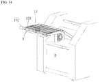
- FIG. 1 shows an overall view of the automatic cloth spreading machine of one embodiment of the present invention
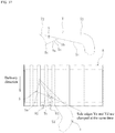
- FIG. 2 to FIG. 34 show individual devices that are parts of the automatic cloth spreading machine of FIG. 1 .
- the directions of front, rear, right, left, up, and down refer to those directions in the state of FIG. 1 .
- corner end locating rollers 44, 45 stop rotating, and the corner end Ya or a portion near the corner end Ya of the cloth Y is tucked and held between the corner end locating rollers 44, 45, which completes a corner end locating task.
- the corner end receiving device 5 has a chuck 51 disposed under the corner end locating rollers 44, 45, and a forward-backward moving device (extending-contracting cylinder 52) that moves the chuck 51 forward and backward in the left-right direction (see FIG. 1 ) within a range directly under a contact portion of the corner end locating rollers 44, 45.
- a forward-backward moving device extending-contracting cylinder 52
- the extending-contracting cylinder 52 of the corner end receiving device 5 extends and moves the chuck 51 forward in a leftward direction as indicated by the imaginary lines in FIG. 10 .
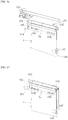
- the edge locating conveyor 8 that is driven by a motor 81 is installed to the right of the platform 64 and the upper pressing plate 65.
- the edge locating conveyor 8 is formed by a plurality of (in the shown example, nine) thin belts 8a extending in the left-right direction indicated in FIG. 1 that is disposed at intervals in the front-rear direction indicated in FIG. 1 .
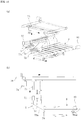
- the two-position holding device 7 has: a pair of holding chucks 71, 72 mounted at a rear end and a front end, respectively, of a coupling rod 70 that extends in the front-rear direction; an upward-downward moving cylinder 73 that moves both the holding chucks 71, 72 upward and downward at the same time; and a forward-backward moving device 7A that moves the holding chucks 71, 72 along with the upward-downward moving cylinder 73 forward and backward in the left-right direction indicated in FIG. 1 .
- the forward-backward moving device 7A has a driving belt 75 that holds the upward-downward moving cylinder 73 in a vertical state, and a motor 74 that rotates a pulley around which the driving belt 75 is wrapped.
- the forward-backward moving device 7A may have any structure as long as it can move the holding chucks 71, 72 in the left-right direction, and a forward-backward moving cylinder may also be used.
- a moving mechanism 7B is provided as a position changing means that moves the two-position holding device 7 in a crosswise direction (the front-rear direction indicated in FIG. 1 ) relative to the delivery direction of the edge locating conveyor 8.
- the moving mechanism 7B has a driving belt 76 on which the forward-backward moving device 7A is fixed, and a motor 77 that moves the two-position holding device 7 along with the forward-backward moving device 7A forward and backward in the front-rear direction by rotating a pulley around which the driving belt 76 is wrapped.
- the moving mechanism 7B may have any structure as long as it can move the two-position holding device 7 in the crosswise direction relative to the delivery direction of the edge locating conveyor 8, and a forward-backward moving cylinder may also be used.
- the coupling rod 70 is provided with a cylinder 70a as an interval changing mechanism that changes the distance between the holding chucks 71, 72 according to the size of the cloth Y to be handled etc. In a preferable configuration, whether or not operation of the cylinder 70a is required and the amount of operation thereof are automatically determined by the controller (not shown) in association with the pulling distance in the horizontal pulling device 6, and operation is performed accordingly.
- the front-side holding chuck 72 is located at a position at which it can hold the front-side end portion (corner end) Yb of the cloth Y laid by the horizontal pulling device 6, while the rear-side holding chuck 71 is located at a position at which it can hold an appropriate portion of the laid cloth Y, on the rear side of the front-side end portion Yb.
- the opening degree of the chuck 69 provided near the rear side of the upper pressing plate 65 can be reduced from the wide-open state indicated by reference sign 69' to help the front-side holding chuck 72 hold the cloth Y.
- the cloth Y is held by the holding chucks 71, 72, the cloth Y is released from the chuck 61, the upper pressing plate 65, and the chuck 69 of the horizontal pulling device 6 that have been holding or restraining the cloth Y.
- the two-position holding device 7 is configured to be able to automatically hold two separate portions of the cloth Y that are on or near the ridge of the fold after the cloth Y has undergone the processing by each of the corner end receiving device 5 and the horizontal pulling device 6.
- the processing leading up to the holding chucks 71, 72 of the two-position holding device 7 holding the cloth Y may be performed by using devices different from those shown in the drawings or may be manually performed by a worker.
- the belts of the edge locating conveyor 8 are rotating in the direction of the arrow in FIG. 18 .
- the right-angled portion Sc of the cloth Y is located near an upper surface of a belt of the edge locating conveyor 8 or at a position at which the right-angled portion Sc comes into contact with the upper surface.
- Air blown by a blowing device 82 installed between upper and lower portions of the belts of the edge locating conveyor 8 causes the right-angled triangular part S to trail in the delivery direction of (move along) the conveyor 8.
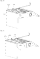
- any mechanism may be used as long as it can reverse the cloth Y clamped by the two clamping chucks 92, 93, and instead of the turning cylinder 91, a motor that rotates the reversing shaft 96 in normal and reverse directions may also be used.
- the two clamping chucks 92, 93 may be configured to move independently of each other based on signals output by the sensors 94, 95 upon detecting the side edge Yc of the cloth Y.
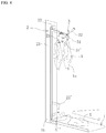
- the roller 10 and the hanging device 11 that hangs the cloth Y received from the vertically inverting device 9 onto the roller 10 are installed directly under a front-side portion of the edge locating conveyor 8, in a positional relationship with the hanging device 11 located above the roller 10.
- the two chucks 111, 112 may be configured to move separately and independently, and in that case, the portion of the side edge Yc of the cloth Y between the two chucks 111, 112 can be held straighter.
- the vertically inverting device 9 turns around and returns to the original position, and moves away from the path of the hanging movable body 11A. Since the roller 10 is disposed such that the rotational axis thereof is parallel to the forward-backward moving direction of the hanging movable body 11A, when the hanging movable body 11A holding the cloth Y in a drooping state moves backward, as shown in FIG.
- the above forward-backward moving mechanism is composed of a driving belt 122 that is coupled to the holding platform 123a and a motor 121 that rotates a pulley around which the driving belt 122 is wrapped.
- a forward-backward moving cylinder may also be used for the forward-backward moving mechanism.
- the transfer conveyor 13 has a belt 133 having a large number of through-holes, a motor 132 that drives the belt 133, and a suction fan 131 that suctions the spread cloth Y on the belt 133 through the through-holes formed in the belt 133.
- the transfer conveyor 13 discharges the cloth Y and transfers (feeds) the cloth Y to the next process (here, the cloth folding machine D).
- the edge clamping device and the automatic cloth spreading machine including this device of the embodiment are configured to be able to move the two-position holding device 7 in the crosswise direction (the front-rear direction in FIG. 1 ) relative to the delivery direction of the edge locating conveyor 8 by the moving mechanism 7B as the position changing means.
- the moving mechanism 7B thereby compensates for the positional deviation of the right-angled triangular part S from the correct clamping position corresponding to the positions of the clamping chucks 92, 93.
- the edge clamping device and the automatic cloth spreading machine including this device of the embodiment can clamp the cloth Y, of which the edge has been located on the edge locating conveyor 8, in a reliable manner and at the correct position by the clamping chucks 92, 93. This makes it possible to process a plurality of types of cloth varying in shape and size by a single edge clamping device.
- two or more of the two-position holding device 7, the edge locating conveyor 8, the clamping chucks 92, 93, and the vertically inverting device 9 may be relatively moved at the same time.
- the sensor 78 detect the right-angled portion Sc of the right-angled triangular part S to obtain the amount of positional deviation from the correct clamping position, and that the amount of movement is determined so as to compensate for this amount of positional deviation.
- the two-position holding device 7 is provided with an interval changing mechanism like the cylinder 70a that changes the distance between the pair of holding chucks.
- the two-position holding device 7 may have three or more holding chucks, and arbitrary two of these holding chucks may be used as the pair of holding chucks according to the dimension of the cloth to be processed etc.
Landscapes
- Engineering & Computer Science (AREA)
- Textile Engineering (AREA)
- Treatment Of Fiber Materials (AREA)
Applications Claiming Priority (2)
| Application Number | Priority Date | Filing Date | Title |
|---|---|---|---|
| JP2018077104A JP7125853B2 (ja) | 2018-04-12 | 2018-04-12 | 縁把持装置およびそれを備えた布類自動展開機 |
| PCT/JP2019/015576 WO2019198741A1 (fr) | 2018-04-12 | 2019-04-10 | Dispositif de préhension de bord et dispositif d'expansion automatique de tissu équipé de celui-ci |
Publications (3)
| Publication Number | Publication Date |
|---|---|
| EP3779018A1 true EP3779018A1 (fr) | 2021-02-17 |
| EP3779018A4 EP3779018A4 (fr) | 2021-06-02 |
| EP3779018B1 EP3779018B1 (fr) | 2023-08-09 |
Family
ID=68164392
Family Applications (1)
| Application Number | Title | Priority Date | Filing Date |
|---|---|---|---|
| EP19785400.3A Active EP3779018B1 (fr) | 2018-04-12 | 2019-04-10 | Dispositif de serrage de bord et machine automatique d'étalement équipé de celui-ci |
Country Status (7)
| Country | Link |
|---|---|
| US (1) | US11359317B2 (fr) |
| EP (1) | EP3779018B1 (fr) |
| JP (1) | JP7125853B2 (fr) |
| CN (1) | CN111936688B (fr) |
| DK (1) | DK3779018T3 (fr) |
| TW (1) | TW201943912A (fr) |
| WO (1) | WO2019198741A1 (fr) |
Families Citing this family (2)
| Publication number | Priority date | Publication date | Assignee | Title |
|---|---|---|---|---|
| JP7470579B2 (ja) * | 2020-06-19 | 2024-04-18 | 株式会社アサヒ製作所 | 洗濯物移載装置、洗濯物移載システム |
| CN114606694B (zh) * | 2022-03-24 | 2023-03-24 | 浙江诺一尔机械设备有限公司 | 一种织物舒展机构、织物舒展装置、织物定型机以及三者的应用 |
Family Cites Families (15)
| Publication number | Priority date | Publication date | Assignee | Title |
|---|---|---|---|---|
| FR2632987B1 (fr) * | 1988-06-16 | 1990-10-26 | Robin Francois | Procede de prehension automatisee de deux coins adjacents d'un linge plat et machine correspondante |
| EP0620310B1 (fr) * | 1993-04-16 | 1997-05-21 | Mitsubishi Jukogyo Kabushiki Kaisha | Dispositif pour étaler une drap rectangulaire |
| JP3379848B2 (ja) | 1993-12-30 | 2003-02-24 | 株式会社トーカイ | 方形状布片の洗濯物の全自動仕上方法および装置 |
| DK0751251T3 (da) * | 1995-01-10 | 2002-08-19 | Tokai Co Ltd | Fremgangsmåde og apparat til automatisk slutbehandling af firkantede klædestykker |
| MX9704866A (es) * | 1996-09-13 | 1998-04-30 | Kikuchi Web Tech Co Ltd | Aparato procesador de material tejido del tipo de banda. |
| US6533267B1 (en) * | 1999-04-30 | 2003-03-18 | Texpa Maschinenbau Gmbh & Co. Kg | Method and apparatus for the alignment of textile material sections |
| JP4268747B2 (ja) * | 2000-10-10 | 2009-05-27 | 株式会社プレックス | 矩形布片の展開方法及び展開装置 |
| JP4444478B2 (ja) * | 2000-10-11 | 2010-03-31 | 株式会社プレックス | 矩形布片の供給装置における傾き補正装置 |
| JP5145605B2 (ja) | 2008-06-19 | 2013-02-20 | セブン ドリーマーズ ラボラトリーズ,インコーポレイテッド | 変形性薄物展開装置 |
| JP5367426B2 (ja) * | 2009-03-23 | 2013-12-11 | 株式会社プレックス | 矩形布片展開方法 |
| JP5396155B2 (ja) * | 2009-05-26 | 2014-01-22 | 株式会社プレックス | 布物の自動展開投入装置 |
| JP5581019B2 (ja) * | 2009-07-31 | 2014-08-27 | 株式会社プレックス | 方形状布類展開装置 |
| CN103237937B (zh) * | 2010-12-01 | 2017-02-15 | 七梦科技株式会社 | 变形性薄片物展开装置和变形性薄片物展开方法 |
| CN105442231B (zh) * | 2015-11-30 | 2017-12-01 | 湖州丝艺丝绸有限公司 | 蚕丝被内丝胎的丝绸棉兜拉伸驱动装置 |
| JP2017176388A (ja) * | 2016-03-30 | 2017-10-05 | ブラザー工業株式会社 | 布送り装置とミシン |
-
2018
- 2018-04-12 JP JP2018077104A patent/JP7125853B2/ja active Active
-
2019
- 2019-04-10 CN CN201980024805.0A patent/CN111936688B/zh active Active
- 2019-04-10 EP EP19785400.3A patent/EP3779018B1/fr active Active
- 2019-04-10 US US17/046,030 patent/US11359317B2/en active Active
- 2019-04-10 WO PCT/JP2019/015576 patent/WO2019198741A1/fr not_active Ceased
- 2019-04-10 DK DK19785400.3T patent/DK3779018T3/da active
- 2019-04-11 TW TW108112628A patent/TW201943912A/zh unknown
Also Published As
| Publication number | Publication date |
|---|---|
| JP2019183334A (ja) | 2019-10-24 |
| US11359317B2 (en) | 2022-06-14 |
| JP7125853B2 (ja) | 2022-08-25 |
| TW201943912A (zh) | 2019-11-16 |
| CN111936688B (zh) | 2023-10-20 |
| EP3779018B1 (fr) | 2023-08-09 |
| WO2019198741A1 (fr) | 2019-10-17 |
| US20210032791A1 (en) | 2021-02-04 |
| DK3779018T3 (da) | 2023-11-06 |
| CN111936688A (zh) | 2020-11-13 |
| EP3779018A4 (fr) | 2021-06-02 |
Similar Documents
| Publication | Publication Date | Title |
|---|---|---|
| US11408118B2 (en) | Cloth clamping chuck and cloth handling device | |
| US5440810A (en) | Apparatus for feeding and spreading laundry articles | |
| EP3677714A1 (fr) | Mandrin de serrage de tissu et dispositif de manipulation de tissu | |
| JP2019520104A (ja) | 洗濯物後処理装置へと洗濯物を供給するための方法並びに装置 | |
| JP3781376B1 (ja) | 布類展張搬送方法および装置 | |
| EP3779018B1 (fr) | Dispositif de serrage de bord et machine automatique d'étalement équipé de celui-ci | |
| EP3359725B1 (fr) | Dispositif et procédé pour la réorientation/l'orientation et l'alignement d'étoffe | |
| JP5367426B2 (ja) | 矩形布片展開方法 | |
| JP7308589B2 (ja) | 布類分別装置を備える布類自動展開機 | |
| EP3677715B1 (fr) | Machine automatique d'étalement de tissu | |
| WO2017182309A1 (fr) | Dispositif de transfert de linge, et procédé de transfert de tissu d'un transporteur à un rouleau | |
| JP6904856B2 (ja) | 載せ掛け装置およびそれを備えた布類自動展開機 | |
| JP2005131005A (ja) | 布類供給方法および装置ならびに同装置を用いた布類折畳み装置 | |
| JP4071763B2 (ja) | 布類供給方法および装置 | |
| JP7705159B2 (ja) | 布類を拡げる布類拡げ装置とその拡げた布類を次工程に搬送する布類投入装置 |
Legal Events
| Date | Code | Title | Description |
|---|---|---|---|
| STAA | Information on the status of an ep patent application or granted ep patent |
Free format text: STATUS: THE INTERNATIONAL PUBLICATION HAS BEEN MADE |
|
| PUAI | Public reference made under article 153(3) epc to a published international application that has entered the european phase |
Free format text: ORIGINAL CODE: 0009012 |
|
| STAA | Information on the status of an ep patent application or granted ep patent |
Free format text: STATUS: REQUEST FOR EXAMINATION WAS MADE |
|
| 17P | Request for examination filed |
Effective date: 20201008 |
|
| AK | Designated contracting states |
Kind code of ref document: A1 Designated state(s): AL AT BE BG CH CY CZ DE DK EE ES FI FR GB GR HR HU IE IS IT LI LT LU LV MC MK MT NL NO PL PT RO RS SE SI SK SM TR |
|
| AX | Request for extension of the european patent |
Extension state: BA ME |
|
| REG | Reference to a national code |
Ref country code: DE Ref legal event code: R079 Ipc: D06F0067040000 Ref country code: DE Ref legal event code: R079 Ref document number: 602019034692 Country of ref document: DE Free format text: PREVIOUS MAIN CLASS: D06C0003000000 Ipc: D06F0067040000 |
|
| A4 | Supplementary search report drawn up and despatched |
Effective date: 20210430 |
|
| RIC1 | Information provided on ipc code assigned before grant |
Ipc: D06F 67/04 20060101AFI20210423BHEP Ipc: D06F 95/00 20060101ALN20210423BHEP |
|
| DAV | Request for validation of the european patent (deleted) | ||
| DAX | Request for extension of the european patent (deleted) | ||
| GRAP | Despatch of communication of intention to grant a patent |
Free format text: ORIGINAL CODE: EPIDOSNIGR1 |
|
| STAA | Information on the status of an ep patent application or granted ep patent |
Free format text: STATUS: GRANT OF PATENT IS INTENDED |
|
| INTG | Intention to grant announced |
Effective date: 20230403 |
|
| GRAS | Grant fee paid |
Free format text: ORIGINAL CODE: EPIDOSNIGR3 |
|
| GRAA | (expected) grant |
Free format text: ORIGINAL CODE: 0009210 |
|
| STAA | Information on the status of an ep patent application or granted ep patent |
Free format text: STATUS: THE PATENT HAS BEEN GRANTED |
|
| AK | Designated contracting states |
Kind code of ref document: B1 Designated state(s): AL AT BE BG CH CY CZ DE DK EE ES FI FR GB GR HR HU IE IS IT LI LT LU LV MC MK MT NL NO PL PT RO RS SE SI SK SM TR |
|
| REG | Reference to a national code |
Ref country code: GB Ref legal event code: FG4D |
|
| REG | Reference to a national code |
Ref country code: CH Ref legal event code: EP |
|
| REG | Reference to a national code |
Ref country code: IE Ref legal event code: FG4D |
|
| REG | Reference to a national code |
Ref country code: DE Ref legal event code: R096 Ref document number: 602019034692 Country of ref document: DE |
|
| REG | Reference to a national code |
Ref country code: DK Ref legal event code: T3 Effective date: 20231101 |
|
| REG | Reference to a national code |
Ref country code: LT Ref legal event code: MG9D |
|
| REG | Reference to a national code |
Ref country code: NL Ref legal event code: MP Effective date: 20230809 |
|
| REG | Reference to a national code |
Ref country code: AT Ref legal event code: MK05 Ref document number: 1597638 Country of ref document: AT Kind code of ref document: T Effective date: 20230809 |
|
| PG25 | Lapsed in a contracting state [announced via postgrant information from national office to epo] |
Ref country code: GR Free format text: LAPSE BECAUSE OF FAILURE TO SUBMIT A TRANSLATION OF THE DESCRIPTION OR TO PAY THE FEE WITHIN THE PRESCRIBED TIME-LIMIT Effective date: 20231110 |
|
| PG25 | Lapsed in a contracting state [announced via postgrant information from national office to epo] |
Ref country code: IS Free format text: LAPSE BECAUSE OF FAILURE TO SUBMIT A TRANSLATION OF THE DESCRIPTION OR TO PAY THE FEE WITHIN THE PRESCRIBED TIME-LIMIT Effective date: 20231209 |
|
| PG25 | Lapsed in a contracting state [announced via postgrant information from national office to epo] |
Ref country code: SE Free format text: LAPSE BECAUSE OF FAILURE TO SUBMIT A TRANSLATION OF THE DESCRIPTION OR TO PAY THE FEE WITHIN THE PRESCRIBED TIME-LIMIT Effective date: 20230809 Ref country code: RS Free format text: LAPSE BECAUSE OF FAILURE TO SUBMIT A TRANSLATION OF THE DESCRIPTION OR TO PAY THE FEE WITHIN THE PRESCRIBED TIME-LIMIT Effective date: 20230809 Ref country code: PT Free format text: LAPSE BECAUSE OF FAILURE TO SUBMIT A TRANSLATION OF THE DESCRIPTION OR TO PAY THE FEE WITHIN THE PRESCRIBED TIME-LIMIT Effective date: 20231211 Ref country code: NO Free format text: LAPSE BECAUSE OF FAILURE TO SUBMIT A TRANSLATION OF THE DESCRIPTION OR TO PAY THE FEE WITHIN THE PRESCRIBED TIME-LIMIT Effective date: 20231109 Ref country code: NL Free format text: LAPSE BECAUSE OF FAILURE TO SUBMIT A TRANSLATION OF THE DESCRIPTION OR TO PAY THE FEE WITHIN THE PRESCRIBED TIME-LIMIT Effective date: 20230809 Ref country code: LV Free format text: LAPSE BECAUSE OF FAILURE TO SUBMIT A TRANSLATION OF THE DESCRIPTION OR TO PAY THE FEE WITHIN THE PRESCRIBED TIME-LIMIT Effective date: 20230809 Ref country code: LT Free format text: LAPSE BECAUSE OF FAILURE TO SUBMIT A TRANSLATION OF THE DESCRIPTION OR TO PAY THE FEE WITHIN THE PRESCRIBED TIME-LIMIT Effective date: 20230809 Ref country code: IS Free format text: LAPSE BECAUSE OF FAILURE TO SUBMIT A TRANSLATION OF THE DESCRIPTION OR TO PAY THE FEE WITHIN THE PRESCRIBED TIME-LIMIT Effective date: 20231209 Ref country code: HR Free format text: LAPSE BECAUSE OF FAILURE TO SUBMIT A TRANSLATION OF THE DESCRIPTION OR TO PAY THE FEE WITHIN THE PRESCRIBED TIME-LIMIT Effective date: 20230809 Ref country code: GR Free format text: LAPSE BECAUSE OF FAILURE TO SUBMIT A TRANSLATION OF THE DESCRIPTION OR TO PAY THE FEE WITHIN THE PRESCRIBED TIME-LIMIT Effective date: 20231110 Ref country code: FI Free format text: LAPSE BECAUSE OF FAILURE TO SUBMIT A TRANSLATION OF THE DESCRIPTION OR TO PAY THE FEE WITHIN THE PRESCRIBED TIME-LIMIT Effective date: 20230809 Ref country code: AT Free format text: LAPSE BECAUSE OF FAILURE TO SUBMIT A TRANSLATION OF THE DESCRIPTION OR TO PAY THE FEE WITHIN THE PRESCRIBED TIME-LIMIT Effective date: 20230809 |
|
| PG25 | Lapsed in a contracting state [announced via postgrant information from national office to epo] |
Ref country code: PL Free format text: LAPSE BECAUSE OF FAILURE TO SUBMIT A TRANSLATION OF THE DESCRIPTION OR TO PAY THE FEE WITHIN THE PRESCRIBED TIME-LIMIT Effective date: 20230809 |
|
| PG25 | Lapsed in a contracting state [announced via postgrant information from national office to epo] |
Ref country code: ES Free format text: LAPSE BECAUSE OF FAILURE TO SUBMIT A TRANSLATION OF THE DESCRIPTION OR TO PAY THE FEE WITHIN THE PRESCRIBED TIME-LIMIT Effective date: 20230809 |
|
| PG25 | Lapsed in a contracting state [announced via postgrant information from national office to epo] |
Ref country code: SM Free format text: LAPSE BECAUSE OF FAILURE TO SUBMIT A TRANSLATION OF THE DESCRIPTION OR TO PAY THE FEE WITHIN THE PRESCRIBED TIME-LIMIT Effective date: 20230809 Ref country code: RO Free format text: LAPSE BECAUSE OF FAILURE TO SUBMIT A TRANSLATION OF THE DESCRIPTION OR TO PAY THE FEE WITHIN THE PRESCRIBED TIME-LIMIT Effective date: 20230809 Ref country code: ES Free format text: LAPSE BECAUSE OF FAILURE TO SUBMIT A TRANSLATION OF THE DESCRIPTION OR TO PAY THE FEE WITHIN THE PRESCRIBED TIME-LIMIT Effective date: 20230809 Ref country code: EE Free format text: LAPSE BECAUSE OF FAILURE TO SUBMIT A TRANSLATION OF THE DESCRIPTION OR TO PAY THE FEE WITHIN THE PRESCRIBED TIME-LIMIT Effective date: 20230809 Ref country code: CZ Free format text: LAPSE BECAUSE OF FAILURE TO SUBMIT A TRANSLATION OF THE DESCRIPTION OR TO PAY THE FEE WITHIN THE PRESCRIBED TIME-LIMIT Effective date: 20230809 Ref country code: SK Free format text: LAPSE BECAUSE OF FAILURE TO SUBMIT A TRANSLATION OF THE DESCRIPTION OR TO PAY THE FEE WITHIN THE PRESCRIBED TIME-LIMIT Effective date: 20230809 |
|
| REG | Reference to a national code |
Ref country code: DE Ref legal event code: R097 Ref document number: 602019034692 Country of ref document: DE |
|
| PG25 | Lapsed in a contracting state [announced via postgrant information from national office to epo] |
Ref country code: IT Free format text: LAPSE BECAUSE OF FAILURE TO SUBMIT A TRANSLATION OF THE DESCRIPTION OR TO PAY THE FEE WITHIN THE PRESCRIBED TIME-LIMIT Effective date: 20230809 |
|
| PLBE | No opposition filed within time limit |
Free format text: ORIGINAL CODE: 0009261 |
|
| STAA | Information on the status of an ep patent application or granted ep patent |
Free format text: STATUS: NO OPPOSITION FILED WITHIN TIME LIMIT |
|
| 26N | No opposition filed |
Effective date: 20240513 |
|
| PG25 | Lapsed in a contracting state [announced via postgrant information from national office to epo] |
Ref country code: SI Free format text: LAPSE BECAUSE OF FAILURE TO SUBMIT A TRANSLATION OF THE DESCRIPTION OR TO PAY THE FEE WITHIN THE PRESCRIBED TIME-LIMIT Effective date: 20230809 |
|
| PG25 | Lapsed in a contracting state [announced via postgrant information from national office to epo] |
Ref country code: BG Free format text: LAPSE BECAUSE OF FAILURE TO SUBMIT A TRANSLATION OF THE DESCRIPTION OR TO PAY THE FEE WITHIN THE PRESCRIBED TIME-LIMIT Effective date: 20230809 |
|
| PG25 | Lapsed in a contracting state [announced via postgrant information from national office to epo] |
Ref country code: MC Free format text: LAPSE BECAUSE OF FAILURE TO SUBMIT A TRANSLATION OF THE DESCRIPTION OR TO PAY THE FEE WITHIN THE PRESCRIBED TIME-LIMIT Effective date: 20230809 |
|
| PG25 | Lapsed in a contracting state [announced via postgrant information from national office to epo] |
Ref country code: MC Free format text: LAPSE BECAUSE OF FAILURE TO SUBMIT A TRANSLATION OF THE DESCRIPTION OR TO PAY THE FEE WITHIN THE PRESCRIBED TIME-LIMIT Effective date: 20230809 Ref country code: BG Free format text: LAPSE BECAUSE OF FAILURE TO SUBMIT A TRANSLATION OF THE DESCRIPTION OR TO PAY THE FEE WITHIN THE PRESCRIBED TIME-LIMIT Effective date: 20230809 |
|
| REG | Reference to a national code |
Ref country code: CH Ref legal event code: PL |
|
| PG25 | Lapsed in a contracting state [announced via postgrant information from national office to epo] |
Ref country code: LU Free format text: LAPSE BECAUSE OF NON-PAYMENT OF DUE FEES Effective date: 20240410 |
|
| GBPC | Gb: european patent ceased through non-payment of renewal fee |
Effective date: 20240410 |
|
| PG25 | Lapsed in a contracting state [announced via postgrant information from national office to epo] |
Ref country code: LU Free format text: LAPSE BECAUSE OF NON-PAYMENT OF DUE FEES Effective date: 20240410 |
|
| PG25 | Lapsed in a contracting state [announced via postgrant information from national office to epo] |
Ref country code: GB Free format text: LAPSE BECAUSE OF NON-PAYMENT OF DUE FEES Effective date: 20240410 |
|
| PG25 | Lapsed in a contracting state [announced via postgrant information from national office to epo] |
Ref country code: FR Free format text: LAPSE BECAUSE OF NON-PAYMENT OF DUE FEES Effective date: 20240430 |
|
| PG25 | Lapsed in a contracting state [announced via postgrant information from national office to epo] |
Ref country code: GB Free format text: LAPSE BECAUSE OF NON-PAYMENT OF DUE FEES Effective date: 20240410 Ref country code: FR Free format text: LAPSE BECAUSE OF NON-PAYMENT OF DUE FEES Effective date: 20240430 Ref country code: CH Free format text: LAPSE BECAUSE OF NON-PAYMENT OF DUE FEES Effective date: 20240430 |
|
| PG25 | Lapsed in a contracting state [announced via postgrant information from national office to epo] |
Ref country code: IE Free format text: LAPSE BECAUSE OF NON-PAYMENT OF DUE FEES Effective date: 20240410 |
|
| PGFP | Annual fee paid to national office [announced via postgrant information from national office to epo] |
Ref country code: DE Payment date: 20250425 Year of fee payment: 7 |
|
| PGFP | Annual fee paid to national office [announced via postgrant information from national office to epo] |
Ref country code: DK Payment date: 20250429 Year of fee payment: 7 |
|
| PGFP | Annual fee paid to national office [announced via postgrant information from national office to epo] |
Ref country code: BE Payment date: 20250426 Year of fee payment: 7 |
|
| PG25 | Lapsed in a contracting state [announced via postgrant information from national office to epo] |
Ref country code: CY Free format text: LAPSE BECAUSE OF FAILURE TO SUBMIT A TRANSLATION OF THE DESCRIPTION OR TO PAY THE FEE WITHIN THE PRESCRIBED TIME-LIMIT; INVALID AB INITIO Effective date: 20190410 |
|
| PG25 | Lapsed in a contracting state [announced via postgrant information from national office to epo] |
Ref country code: HU Free format text: LAPSE BECAUSE OF FAILURE TO SUBMIT A TRANSLATION OF THE DESCRIPTION OR TO PAY THE FEE WITHIN THE PRESCRIBED TIME-LIMIT; INVALID AB INITIO Effective date: 20190410 |