EP3779083A1 - Structure de support de panneau de verre - Google Patents
Structure de support de panneau de verre Download PDFInfo
- Publication number
- EP3779083A1 EP3779083A1 EP19777384.9A EP19777384A EP3779083A1 EP 3779083 A1 EP3779083 A1 EP 3779083A1 EP 19777384 A EP19777384 A EP 19777384A EP 3779083 A1 EP3779083 A1 EP 3779083A1
- Authority
- EP
- European Patent Office
- Prior art keywords
- glass
- structural sealant
- support structure
- glazed
- glazed glass
- Prior art date
- Legal status (The legal status is an assumption and is not a legal conclusion. Google has not performed a legal analysis and makes no representation as to the accuracy of the status listed.)
- Withdrawn
Links
Images

Classifications
-
- E—FIXED CONSTRUCTIONS
- E06—DOORS, WINDOWS, SHUTTERS, OR ROLLER BLINDS IN GENERAL; LADDERS
- E06B—FIXED OR MOVABLE CLOSURES FOR OPENINGS IN BUILDINGS, VEHICLES, FENCES OR LIKE ENCLOSURES IN GENERAL, e.g. DOORS, WINDOWS, BLINDS, GATES
- E06B3/00—Window sashes, door leaves, or like elements for closing wall or like openings; Layout of fixed or moving closures, e.g. windows in wall or like openings; Features of rigidly-mounted outer frames relating to the mounting of wing frames
- E06B3/54—Fixing of glass panes or like plates
- E06B3/56—Fixing of glass panes or like plates by means of putty, cement, or adhesives only
-
- E—FIXED CONSTRUCTIONS
- E04—BUILDING
- E04B—GENERAL BUILDING CONSTRUCTIONS; WALLS, e.g. PARTITIONS; ROOFS; FLOORS; CEILINGS; INSULATION OR OTHER PROTECTION OF BUILDINGS
- E04B2/00—Walls, e.g. partitions, for buildings; Wall construction with regard to insulation; Connections specially adapted to walls
- E04B2/88—Curtain walls
-
- E—FIXED CONSTRUCTIONS
- E06—DOORS, WINDOWS, SHUTTERS, OR ROLLER BLINDS IN GENERAL; LADDERS
- E06B—FIXED OR MOVABLE CLOSURES FOR OPENINGS IN BUILDINGS, VEHICLES, FENCES OR LIKE ENCLOSURES IN GENERAL, e.g. DOORS, WINDOWS, BLINDS, GATES
- E06B3/00—Window sashes, door leaves, or like elements for closing wall or like openings; Layout of fixed or moving closures, e.g. windows in wall or like openings; Features of rigidly-mounted outer frames relating to the mounting of wing frames
- E06B3/54—Fixing of glass panes or like plates
- E06B3/5427—Fixing of glass panes or like plates the panes mounted flush with the surrounding frame or with the surrounding panes
-
- E—FIXED CONSTRUCTIONS
- E06—DOORS, WINDOWS, SHUTTERS, OR ROLLER BLINDS IN GENERAL; LADDERS
- E06B—FIXED OR MOVABLE CLOSURES FOR OPENINGS IN BUILDINGS, VEHICLES, FENCES OR LIKE ENCLOSURES IN GENERAL, e.g. DOORS, WINDOWS, BLINDS, GATES
- E06B3/00—Window sashes, door leaves, or like elements for closing wall or like openings; Layout of fixed or moving closures, e.g. windows in wall or like openings; Features of rigidly-mounted outer frames relating to the mounting of wing frames
- E06B3/66—Units comprising two or more parallel glass or like panes permanently secured together
- E06B3/663—Elements for spacing panes
- E06B3/66309—Section members positioned at the edges of the glazing unit
- E06B3/66366—Section members positioned at the edges of the glazing unit specially adapted for units comprising more than two panes or for attaching intermediate sheets
-
- Y—GENERAL TAGGING OF NEW TECHNOLOGICAL DEVELOPMENTS; GENERAL TAGGING OF CROSS-SECTIONAL TECHNOLOGIES SPANNING OVER SEVERAL SECTIONS OF THE IPC; TECHNICAL SUBJECTS COVERED BY FORMER USPC CROSS-REFERENCE ART COLLECTIONS [XRACs] AND DIGESTS
- Y02—TECHNOLOGIES OR APPLICATIONS FOR MITIGATION OR ADAPTATION AGAINST CLIMATE CHANGE
- Y02A—TECHNOLOGIES FOR ADAPTATION TO CLIMATE CHANGE
- Y02A30/00—Adapting or protecting infrastructure or their operation
- Y02A30/24—Structural elements or technologies for improving thermal insulation
- Y02A30/249—Glazing, e.g. vacuum glazing
-
- Y—GENERAL TAGGING OF NEW TECHNOLOGICAL DEVELOPMENTS; GENERAL TAGGING OF CROSS-SECTIONAL TECHNOLOGIES SPANNING OVER SEVERAL SECTIONS OF THE IPC; TECHNICAL SUBJECTS COVERED BY FORMER USPC CROSS-REFERENCE ART COLLECTIONS [XRACs] AND DIGESTS
- Y02—TECHNOLOGIES OR APPLICATIONS FOR MITIGATION OR ADAPTATION AGAINST CLIMATE CHANGE
- Y02B—CLIMATE CHANGE MITIGATION TECHNOLOGIES RELATED TO BUILDINGS, e.g. HOUSING, HOUSE APPLIANCES OR RELATED END-USER APPLICATIONS
- Y02B80/00—Architectural or constructional elements improving the thermal performance of buildings
- Y02B80/22—Glazing, e.g. vaccum glazing
Definitions
- the present invention relates to a glass panel support structure.
- SSG structural silicone glazing
- Patent Literature 1 As a construction system for supporting glass panels that constitute wall surfaces of a building, a structural silicone glazing (SSG) system, as described in Patent Literature 1, has been conventionally known.
- SSG systems glass panels are bonded to support members constituted by aluminum frames using first structural sealants, thereby supporting the glass panels.
- the SSG systems are marked by glass panels fitted into aluminum frames, which enable transmission of loads of the glass panels to the aluminum frames, and also by flatter and smoother surfaces on the outdoor side compared to conventional curtain walls for supporting glass panels.
- Patent Literature 1 Japanese Unexamined Patent Application Publication No. 2017-179987
- the load ratio in a structural sealant portion at negative pressure is determined based on the ratio between a first width dimension of the first structural sealant that connects the multi-glazed glass and the support member, and a second width dimension between the sheets of glass of the multi-glazed glass panel.
- the first width dimension and the second width dimension are generally set to the same dimension. Accordingly, a third width dimension of an entire portion including the second structural sealant and desiccant provided between the sheets of multi-glazed glass is conventionally larger than the first width dimension.
- a backup material is disposed at a position closer to the center along a direction perpendicular to the indoor and outdoor directions of the glass, and the backup material bears negative pressure loads and positive pressure loads applied to the glass.
- the first structural sealant could peel off because of deterioration of the boundary surface between the first structural sealant and the backup material, and deterioration of the first structural sealant could be promoted because of moisture entering through the boundary surface. Also, because of bubbles entering the bonded surface between the multi-glazed glass and the first structural sealant provided on the indoor side of the multi-glazed glass, the bonded surface could be reduced, and the bearing force of the first structural sealant could also be reduced.
- the present invention has been made in view of such a problem, and a purpose thereof is to provide a glass panel support structure in which the bonding state of a structural sealant provided between a glass panel and a frame can be visually checked.
- the present invention employs the following embodiment.
- the bonding state of a structural sealant provided between a glass panel and a frame can be visually checked.
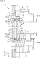
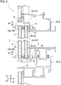
- FIGS. 1 and 2 illustrate an example in which the glass panel support structure of the present embodiment is employed in an SSG system in a curtain wall 1 of a building.
- the glass panel support structure supports multi-glazed glass 3 of which a circumferential edge part 3a is bonded to a frame 2 that frames all sides.
- the curtain wall 1 includes the frame 2 and the multi-glazed glass 3.
- the frame 2 is configured to frame all sides with multiple vertical frames 2A and lateral frames 2B such as to form a lattice.
- the multi-glazed glass 3 is fitted in the opening part of the frame 2.
- the multi-glazed glass 3 and the frame 2 are bonded to each other using a structural sealant (a first structural sealant 4, which will be described later) such that the frame 2 supports a load on the multi-glazed glass 3.
- a support part for supporting the multi-glazed glass 3 is not provided on the side surface of the multi-glazed glass 3 on the outdoor side.
- a direction connecting the outdoor side and the indoor side will be referred to as an indoor and outdoor direction X1.
- a horizontal direction connecting the left side and the right side will be referred to as a lateral direction X2.
- the state of the member or component provided in the opening part will be described using the indoor and outdoor directions X1 and the lateral directions X2.
- a direction perpendicular to the indoor and outdoor directions X1 is defined as a first direction.
- the side closer to the center of the multi-glazed glass 3 will be referred to as the inner circumferential side
- the side closer to the frame 2 will be referred to as the outer circumferential side.
- Each vertical frame 2A is provided along a vertical direction X3 of the building.
- Each vertical frame 2A is fixed to a building framework, such as a pillar, beam, and floor, using an angle member or the like, which is not illustrated.
- Each lateral frame 2B is laid along a lateral direction X2 between neighboring vertical frames 2A and fixed to the vertical frames 2A.
- the frame 2 includes a frame body 21, and a glass attachment part 22 disposed on the outdoor side of the frame body 21.
- Each of the frame body 21 and the glass attachment part 22 may be made of a metal material, such as aluminum, and may be formed by extrusion molding of the metal material, for example.
- the frame body 21 is configured to be attachable to a building framework.
- the glass attachment part 22 includes an outer side support surface 22a facing the outdoor side, and a glass support surface 22b facing an outer circumferential edge 3c of the multi-glazed glass 3.
- An indoor side portion of the circumferential edge part 3a of the multi-glazed glass 3 is bonded to and held by the outer side support surface 22a via the first structural sealant 4.
- the outer circumferential edge 3c of the multi-glazed glass 3 is formed by edge surfaces of glass plates 3A and 3B and an edge surface of a second structural sealant 31.
- the glass support surface 22b is positioned lower than the multi-glazed glass 3 and supports the multi-glazed glass 3 with the outer circumferential edge 3c placed on the glass support surface 22b via a setting block 33.
- Multiple setting blocks 33 are spaced out along a lateral direction X2 of the multi-glazed glass 3.
- the glass support surface 22b may be formed only in a portion provided with the setting blocks 33.
- a widening space is formed such that the distance from the outer circumferential edge 3c of the multi-glazed glass 3 across the space becomes larger from the indoor side toward the outdoor side, as illustrated in FIG. 1 .
- the first structural sealant 4 bonds each of the four edge parts of the indoor-side glass plate 3A of the multi-glazed glass 3 and the outer side support surface 22a of the frame 2 together.
- the first structural sealant 4 is filled from the position of the outer circumferential edge 3c of the multi-glazed glass 3 to an outer circumferential edge 5a of a backup material 5, which will be described later, in a first direction.
- the first structural sealant 4 is spaced apart from the glass support surface 22b of the frame 2.
- the backup material 5 is provided on the inner circumferential side of the first structural sealant 4.
- the backup material 5 is in close contact with the indoor-side glass plate 3A of the multi-glazed glass 3 and the outer side support surface 22a of the frame 2 and is held therebetween.
- the backup material 5 may be made of an elastic body, such as expandable polyethylene foam, for example.
- the configurations of the first structural sealant 4 and the backup material 5 are the same over the entire circumference of the circumferential edge part 3a of the multi-glazed glass 3.
- the multi-glazed glass 3 is disposed at a position such that the circumferential edge part 3a thereof faces the outer side support surface 22a of the glass attachment part 22.
- the multi-glazed glass 3 has a configuration in which a space 3b is provided between the two glass plates 3A and 3B that are arranged to face each other and to be spaced apart from each other, and dry air is sealed in the space 3b.
- a spacer 30 is provided to maintain a constant distance between the glass plates 3A and 3B.
- the spacer 30 includes the second structural sealant 31 and a spacer member 32.
- the second structural sealant 31 is provided on the outer circumferential side of the spacer member 32 to bond the glass plates 3A and 3B together, and has a water stop function.
- the spacer member 32 is provided on the inner circumferential side of the second structural sealant 31.
- the spacer member 32 may be constituted by desiccant to prevent dew condensation within the space 3b of the multi-glazed glass 3, or may also be constituted by a metal material or a resin material.
- An inner circumferential surface 30a of the spacer 30 (or an inner circumferential surface 32a of the spacer member 32) is positioned on the outer circumferential side with respect to an inner circumferential surface 4a of the first structural sealant 4 (or a boundary surface 4A between the first structural sealant 4 and the backup material 5).
- a height dimension h1 of the spacer 30 in a first direction is smaller than a height dimension h2 of the first structural sealant 4 (h1 ⁇ h2).
- the side closer to the center of the multi-glazed glass 3 along a first direction is defined as the inner circumferential side
- the side closer to the end part (the outer circumferential edge 3c) of the multi-glazed glass 3 is defined as the outer circumferential side.
- the height dimension h2 of the first structural sealant 4 and the height dimension h1 of the second structural sealant 31 described above are determined as follows.
- the glass plates 3A and 3B respectively bear substantially halves (such as 53:47) of a wind load or the like.
- the first structural sealant 4 supports a load on the multi-glazed glass 3 from the indoor side, and the height of the first structural sealant 4 is determined based on a wind load, irrespective of glass thickness.
- the height of the second structural sealant 31 between the glass plates 3A and 3B is reduced, the wind pressure resistance of the glass panel support structure can be ensured. Therefore, the height of the second structural sealant 31 is determined depending on the thickness ratio between the glass plates 3A and 3B arranged along an indoor and outdoor direction X1.
- the inner circumferential surface 30a of the spacer 30 provided in the multi-glazed glass 3 is positioned on the outer circumferential side along a first direction, with respect to the inner circumferential surface 4a of the first structural sealant 4 provided between the multi-glazed glass 3 and the frame 2.
- the inner circumferential surface 4a of the first structural sealant 4 is positioned on the inner side with respect to the inner circumferential surface 30a of the spacer 30, so that the bonding state of the first structural sealant 4 can be visually checked from the outdoors through the multi-glazed glass 3. For example, bubbles entering between the indoor-side glass plate 3A of the multi-glazed glass 3 and the first structural sealant 4 can be found.
- a void or peeling off of the first structural sealant 4 can be easily found, and the first structural sealant 4 can be replaced or repaired accordingly. This can prevent the coming off of the multi-glazed glass 3 from the frame 2.
- the inner circumferential surface 30a of the spacer 30 is positioned on the outer circumferential side with respect to the boundary surface 4A between the first structural sealant 4 and the backup material 5. Accordingly, peeling off of the bonded surface of the first structural sealant 4 bonded to the multi-glazed glass 3 or a discoloration state of the first structural sealant 4 can be visually checked from the outdoors through the multi-glazed glass 3. For example, if a plasticizer or the like leaks out of the backup material 5 toward the first structural sealant 4, the bonded surface of the first structural sealant 4 bonded to the multi-glazed glass 3 can be checked.
- the outer circumferential edge of the second structural sealant 31 in the multi-glazed glass 3 and the outer circumferential edge of the first structural sealant 4 are provided at the same position, a load can be smoothly transmitted through a smaller area.
- a moment is generated when the positions of the outer circumferential edges of the second structural sealant 31 and the first structural sealant 4 are shifted from each other, but such a moment is less likely to act in the case of the present embodiment.
- the first structural sealant 4 is provided on the outdoor side with respect to the backup material 5.
- rain water may enter and stand in the first structural sealant 4.
- the temperature of the rain water may be raised by sunlight, making the rain water warm. This may cause peeling off of the bonding interface of the first structural sealant 4 with the circumferential edge part 3a or peeling off of the outer side support surface 22a side of the first structural sealant 4. Accordingly, disposing the first structural sealant 4 on the outdoor side with respect to the backup material 5, as described in the present embodiment, can prevent the problem of deterioration of the bonding interface or the outer side of the first structural sealant 4.
- the first structural sealant 4 is filled from the outer circumferential edge 3c of the multi-glazed glass 3 to the outer circumferential edge 5a of the backup material 5 in a first direction, as illustrated in FIG. 1 . Accordingly, an outer circumferential surface 4b of the first structural sealant 4 will never be positioned on the inner circumferential side with respect to the inner circumferential surface 30a of the spacer 30. As a result, the frame 2 can be made smaller, and the glass opening of the multi-glazed glass 3 can be made larger.
- the first structural sealant 4 is filled to the position of the outer circumferential edge 5a of the backup material 5 in a first direction. In this state, a moment will not be generated, so that a load from the multi-glazed glass 3 equally acts on the first structural sealant 4 with balance.
- the configurations of the first structural sealant 4 and the backup material 5 are the same over the entire circumference of the circumferential edge part 3a of the multi-glazed glass 3. Accordingly, a load from the multi-glazed glass 3 equally acts on the first structural sealant 4 with balance over the entire circumference of the multi-glazed glass 3, thereby restraining worsening of the bonding state and deterioration in durability of the first structural sealant 4.
- a space is formed between the glass support surface 22b of the frame 2 and the outer circumferential surface 4b of the first structural sealant 4, preventing the bonding between the first structural sealant 4 and the glass support surface 22b. Accordingly, the present embodiment prevents the situation where such bonding between the first structural sealant 4 and the glass support surface 22b complexes a stress acting on the first structural sealant 4.
- the first structural sealant 4 will receive the stress from the glass support surface 22b, in addition to the stress from the frame side surface (or the outer side support surface 22a of the frame 2). Receiving such stresses from various directions may cause fracture or damage of the first structural sealant 4, which is disadvantageous. Accordingly, the configuration in which the first structural sealant 4 is not bonded to the glass support surface 22b with a space formed therebetween, as described above, can minimize the contact between the frame 2 and the first structural sealant 4.
- the first structural sealant 4 can be easily viewed from the outdoor side through the multi-glazed glass 3. Accordingly, the visual check of the bonding state of the first structural sealant 4 as described previously can be easily performed.
- the multi-glazed glass 3 is supported by the frame 2 via the first structural sealant 4, and the side surface of the glass plate 3B on the outdoor side is not directly supported by the frame 2. Accordingly, a space is formed between the glass attachment part 22 and the side surface of the glass plate 3B on the outdoor side. As a result, the bonding state of the first structural sealant 4 can be visually checked easily from the outdoor side.
- the bonding state of the first structural sealant 4 provided between the multi-glazed glass 3 and the frame 2 can be visually checked.
- the multi-glazed glass 3 is constituted by the two glass plates 3A and 3B.
- the number of glass plates is not limited to two, and three or more glass plates may be arranged to face one another in the multi-glazed glass.
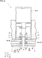
- the position in a height direction of the inner circumferential surface 30a of the spacer 30 (or the inner circumferential surface 32a of the spacer member 32) is lower than the position of the inner circumferential surface 4a of the first structural sealant 4.
- the positional relationship may be as illustrated in FIGS. 3 and 4 as a modification.
- the position in a height direction of the inner circumferential surface 30a of the spacer 30 has only to be identical with or located on the outer circumferential side with respect to the position in a first direction of the inner circumferential surface 4a of the first structural sealant 4.
- the spacer 30 of the multi-glazed glass 3 includes the spacer member and the second structural sealant 31 having a water stop function, and the first structural sealant 4 and the second structural sealant 31 may be arranged such as to overlap each other in an indoor and outdoor direction X1. In this case, the loads applied to the first structural sealant 4 and the second structural sealant 31 will be equal.
- the frame body 21 and the glass attachment part 22 may be constituted by different members, and a seismic isolation mechanism may be provided therebetween, for example.
- the bonding state of a structural sealant provided between a glass panel and a frame can be visually checked.
Landscapes
- Engineering & Computer Science (AREA)
- Civil Engineering (AREA)
- Structural Engineering (AREA)
- Architecture (AREA)
- Physics & Mathematics (AREA)
- Electromagnetism (AREA)
- Load-Bearing And Curtain Walls (AREA)
- Securing Of Glass Panes Or The Like (AREA)
Applications Claiming Priority (2)
| Application Number | Priority Date | Filing Date | Title |
|---|---|---|---|
| JP2018069356A JP7169761B2 (ja) | 2018-03-30 | 2018-03-30 | ガラスパネル支持構造 |
| PCT/JP2019/011171 WO2019188497A1 (fr) | 2018-03-30 | 2019-03-18 | Structure de support de panneau de verre |
Publications (2)
| Publication Number | Publication Date |
|---|---|
| EP3779083A1 true EP3779083A1 (fr) | 2021-02-17 |
| EP3779083A4 EP3779083A4 (fr) | 2021-12-22 |
Family
ID=68058820
Family Applications (1)
| Application Number | Title | Priority Date | Filing Date |
|---|---|---|---|
| EP19777384.9A Withdrawn EP3779083A4 (fr) | 2018-03-30 | 2019-03-18 | Structure de support de panneau de verre |
Country Status (5)
| Country | Link |
|---|---|
| US (1) | US11834894B2 (fr) |
| EP (1) | EP3779083A4 (fr) |
| JP (2) | JP7169761B2 (fr) |
| CA (1) | CA3095705A1 (fr) |
| WO (1) | WO2019188497A1 (fr) |
Families Citing this family (5)
| Publication number | Priority date | Publication date | Assignee | Title |
|---|---|---|---|---|
| JP7445484B2 (ja) * | 2020-03-25 | 2024-03-07 | 株式会社Lixil | 制振装置、枠構造及び窓構造 |
| CN112627410B (zh) * | 2020-12-29 | 2022-04-29 | 山西鼎隆智装科技股份有限公司 | 一种节能型隐框玻璃铝板复合幕墙结构 |
| JP7672254B2 (ja) * | 2021-03-19 | 2025-05-07 | 日本板硝子株式会社 | ガラスパネル構造体及びガラスユニット |
| JP7601716B2 (ja) * | 2021-06-14 | 2024-12-17 | Ykk Ap株式会社 | カーテンウォール |
| FR3154428A1 (fr) * | 2023-10-20 | 2025-04-25 | Saint-Gobain Glass France | système amortisseur pour vitrage isolant sur mur |
Family Cites Families (26)
| Publication number | Priority date | Publication date | Assignee | Title |
|---|---|---|---|---|
| DE2326230B2 (de) * | 1973-05-23 | 1977-07-14 | Schafheutle Albert, Dipl Kfm, 7800 Freiburg | Doppelglasscheibe, insbesondere isolierscheibe |
| US4314424A (en) * | 1979-12-26 | 1982-02-09 | Gordon Stanley J | Thermal window construction |
| DE3621942A1 (de) * | 1986-05-22 | 1987-11-26 | Gartner & Co J | Rahmenlose verglasung |
| NL8703061A (nl) * | 1987-12-17 | 1989-07-17 | Abraham Dees | Methode tot borging van aan een gebouw bevestigd glas of andere gevelvulling als er geen sprake is van een volledige sponning. |
| US4947604A (en) * | 1988-04-25 | 1990-08-14 | Sylvester Michael S | Sealant with uniform spacer particles |
| US5076034A (en) * | 1988-11-15 | 1991-12-31 | Kawneer Company, Inc. | Vertical exterior weather seal |
| IT1231185B (it) * | 1989-03-15 | 1991-11-23 | Siv Soc Italiana Vetro | Dispositivo per l'accoppiamento di vetrate isolanti ad un telaio fisso |
| US6301858B1 (en) * | 1999-09-17 | 2001-10-16 | Ppg Industries Ohio, Inc. | Sealant system for an insulating glass unit |
| KR100411948B1 (ko) * | 2000-03-02 | 2003-12-18 | 주식회사 훌텍 | 커튼월용 조립유리패널 |
| US7676999B2 (en) * | 2005-03-15 | 2010-03-16 | Muridal Inc. | Curtain wall system and method |
| WO2007011540A1 (fr) * | 2005-07-19 | 2007-01-25 | Dow Corning Corporation | Moyen de fixation de structures |
| WO2012103102A1 (fr) * | 2011-01-26 | 2012-08-02 | Dow Corning Corporation | Ensembles pour structure |
| CA2874594C (fr) * | 2012-05-30 | 2020-05-05 | Oldcastle BuildingEnvelope Inc. | Procede et systeme d'isolation de composants structuraux de batiments |
| KR20140123234A (ko) * | 2013-04-12 | 2014-10-22 | 제정원 | 길이조절 및 단열 기능이 동시에 구비된 창문 지지시스템 |
| US11214961B2 (en) * | 2014-02-24 | 2022-01-04 | Fremarq Innovations, Inc. | Window and curtain wall mullions, transoms and systems |
| US9663946B2 (en) * | 2014-02-24 | 2017-05-30 | Fremarq Innovations, Inc. | Curtain wall mullions, transoms and systems |
| KR101630393B1 (ko) * | 2014-06-23 | 2016-06-14 | 주식회사 우성알테크 | 기밀성과 단열성을 갖는 커튼월 |
| KR101697740B1 (ko) * | 2015-07-21 | 2017-01-18 | 주식회사 유니크시스템 | 복합 커튼월의 결합방법 |
| US9752319B1 (en) * | 2016-03-03 | 2017-09-05 | Kurtis E. LeVan | Building facade system |
| JP6584992B2 (ja) | 2016-03-31 | 2019-10-02 | 株式会社Lixil | ガラスパネル支持構造 |
| JP6827768B2 (ja) | 2016-10-26 | 2021-02-10 | コマツNtc株式会社 | 研削盤 |
| KR101763160B1 (ko) * | 2016-12-19 | 2017-08-04 | (주)청송중앙알미늄 | 커튼월 어셈블리 |
| KR101939898B1 (ko) * | 2017-04-05 | 2019-01-17 | 이선중 | 간단한 연결구조로 형성되어 다양한 시공방법이 용이하게 이루어지도록 형성되는 커튼월. |
| KR101908415B1 (ko) * | 2018-03-02 | 2018-10-16 | (주)신창산업 | 단열성능이 향상된 커튼월 어셈블리 |
| CN109518846A (zh) * | 2018-09-16 | 2019-03-26 | 太新能源科技(天津)合伙企业(有限合伙) | 带有柔性连接结构的钙钛矿玻璃幕墙 |
| KR102025651B1 (ko) * | 2019-02-21 | 2019-09-26 | (주)청송중앙알미늄 | 단열성능을 확보한 커튼월 어셈블리 |
-
2018
- 2018-03-30 JP JP2018069356A patent/JP7169761B2/ja active Active
-
2019
- 2019-03-18 EP EP19777384.9A patent/EP3779083A4/fr not_active Withdrawn
- 2019-03-18 US US17/043,632 patent/US11834894B2/en active Active
- 2019-03-18 CA CA3095705A patent/CA3095705A1/fr active Pending
- 2019-03-18 WO PCT/JP2019/011171 patent/WO2019188497A1/fr not_active Ceased
-
2022
- 2022-09-06 JP JP2022141648A patent/JP7373628B2/ja active Active
Also Published As
| Publication number | Publication date |
|---|---|
| EP3779083A4 (fr) | 2021-12-22 |
| JP2019178578A (ja) | 2019-10-17 |
| JP7373628B2 (ja) | 2023-11-02 |
| US20210017804A1 (en) | 2021-01-21 |
| JP2022172309A (ja) | 2022-11-15 |
| CA3095705A1 (fr) | 2019-10-03 |
| US11834894B2 (en) | 2023-12-05 |
| JP7169761B2 (ja) | 2022-11-11 |
| WO2019188497A1 (fr) | 2019-10-03 |
Similar Documents
| Publication | Publication Date | Title |
|---|---|---|
| EP3779083A1 (fr) | Structure de support de panneau de verre | |
| JP4975474B2 (ja) | ガラスカーテンウォールの施工方法 | |
| KR101560353B1 (ko) | 커튼 월의 차양장치 | |
| US8689505B2 (en) | Profile-bending means for frame to be pocketed | |
| EP2568094A1 (fr) | Lucarne, en particulier d'une fenêtre de toit apte à être montée à l'intérieur d'un ensemble de panneaux solaires | |
| EP3563015B1 (fr) | Module de vitre conçu pour être installé sur un cadre de fenêtre et procédé de fabrication de module de vitre | |
| CN103781979A (zh) | 将风撑装配在玻璃墙壁上的装配系统 | |
| CN105074100B (zh) | 内嵌有隔热体的幕墙 | |
| JP3762656B2 (ja) | ガラスカーテンウォール | |
| JP2008138484A (ja) | 複層ガラスの支持構造 | |
| JP2019533779A (ja) | シート材料のフレームアセンブリ | |
| KR20190066505A (ko) | 케이블을 이용하는 외장유리 고정 시스템 | |
| KR20170001383A (ko) | 구조적 성능을 보강한 비노출형 단열 커튼월 시스템 | |
| KR102240604B1 (ko) | 커튼월 프레임의 접합 시스템 및 방법 | |
| KR20170060743A (ko) | 고단열 개폐창 및 이를 포함하는 개폐창 시스템 | |
| KR101553402B1 (ko) | 패널이 장착된 프레임, 이를 이용한 구조체 및 그 시공방법 | |
| JP5052392B2 (ja) | 採光窓枠構造及びその施工方法 | |
| JP6123986B2 (ja) | 窓用板状体の支持構造体 | |
| JP7731792B2 (ja) | リブガラスを用いたガラスファサード工法 | |
| KR101666392B1 (ko) | 조립식 외벽 패널 시스템 및 방법 | |
| JP2006132133A (ja) | 建築用気密テープとその施工方法 | |
| CN111119656B (zh) | 一种装配式内扣单元系统窗及其安装方法 | |
| JP2004218423A (ja) | 外壁の開口部構造 | |
| EP4198246A1 (fr) | Dispositif de montage pour une rainure de fixation d'une unité de verre isolant | |
| JP2024165747A (ja) | 外壁パネルの取付構造 |
Legal Events
| Date | Code | Title | Description |
|---|---|---|---|
| STAA | Information on the status of an ep patent application or granted ep patent |
Free format text: STATUS: THE INTERNATIONAL PUBLICATION HAS BEEN MADE |
|
| PUAI | Public reference made under article 153(3) epc to a published international application that has entered the european phase |
Free format text: ORIGINAL CODE: 0009012 |
|
| STAA | Information on the status of an ep patent application or granted ep patent |
Free format text: STATUS: REQUEST FOR EXAMINATION WAS MADE |
|
| 17P | Request for examination filed |
Effective date: 20201002 |
|
| AK | Designated contracting states |
Kind code of ref document: A1 Designated state(s): AL AT BE BG CH CY CZ DE DK EE ES FI FR GB GR HR HU IE IS IT LI LT LU LV MC MK MT NL NO PL PT RO RS SE SI SK SM TR |
|
| AX | Request for extension of the european patent |
Extension state: BA ME |
|
| RIN1 | Information on inventor provided before grant (corrected) |
Inventor name: ISHII, HISASHI |
|
| RAP1 | Party data changed (applicant data changed or rights of an application transferred) |
Owner name: LIXIL GROUP CORPORATION |
|
| RAP3 | Party data changed (applicant data changed or rights of an application transferred) |
Owner name: LIXIL CORPORATION |
|
| DAV | Request for validation of the european patent (deleted) | ||
| DAX | Request for extension of the european patent (deleted) | ||
| A4 | Supplementary search report drawn up and despatched |
Effective date: 20211122 |
|
| RIC1 | Information provided on ipc code assigned before grant |
Ipc: E06B 3/56 20060101ALI20211116BHEP Ipc: E04B 2/88 20060101AFI20211116BHEP |
|
| RAP3 | Party data changed (applicant data changed or rights of an application transferred) |
Owner name: LIXIL CORPORATION |
|
| RIN1 | Information on inventor provided before grant (corrected) |
Inventor name: ISHII, HISASHI |
|
| STAA | Information on the status of an ep patent application or granted ep patent |
Free format text: STATUS: EXAMINATION IS IN PROGRESS |
|
| 17Q | First examination report despatched |
Effective date: 20230317 |
|
| GRAP | Despatch of communication of intention to grant a patent |
Free format text: ORIGINAL CODE: EPIDOSNIGR1 |
|
| STAA | Information on the status of an ep patent application or granted ep patent |
Free format text: STATUS: GRANT OF PATENT IS INTENDED |
|
| INTG | Intention to grant announced |
Effective date: 20240903 |
|
| STAA | Information on the status of an ep patent application or granted ep patent |
Free format text: STATUS: THE APPLICATION IS DEEMED TO BE WITHDRAWN |
|
| 18D | Application deemed to be withdrawn |
Effective date: 20250104 |