EP3779094B1 - Un lanterneau - Google Patents
Un lanterneau Download PDFInfo
- Publication number
- EP3779094B1 EP3779094B1 EP20210451.9A EP20210451A EP3779094B1 EP 3779094 B1 EP3779094 B1 EP 3779094B1 EP 20210451 A EP20210451 A EP 20210451A EP 3779094 B1 EP3779094 B1 EP 3779094B1
- Authority
- EP
- European Patent Office
- Prior art keywords
- frame
- igu
- edge
- window
- skylight
- Prior art date
- Legal status (The legal status is an assumption and is not a legal conclusion. Google has not performed a legal analysis and makes no representation as to the accuracy of the status listed.)
- Active
Links
Images


Classifications
-
- E—FIXED CONSTRUCTIONS
- E04—BUILDING
- E04D—ROOF COVERINGS; SKY-LIGHTS; GUTTERS; ROOF-WORKING TOOLS
- E04D13/00—Special arrangements or devices in connection with roof coverings; Protection against birds; Roof drainage ; Sky-lights
- E04D13/03—Sky-lights; Domes; Ventilating sky-lights
- E04D13/0305—Supports or connecting means for sky-lights of flat or domed shape
- E04D13/0315—Supports or connecting means for sky-lights of flat or domed shape characterised by a curb frame
-
- E—FIXED CONSTRUCTIONS
- E04—BUILDING
- E04D—ROOF COVERINGS; SKY-LIGHTS; GUTTERS; ROOF-WORKING TOOLS
- E04D13/00—Special arrangements or devices in connection with roof coverings; Protection against birds; Roof drainage ; Sky-lights
- E04D13/03—Sky-lights; Domes; Ventilating sky-lights
- E04D13/033—Sky-lights; Domes; Ventilating sky-lights provided with means for controlling the light-transmission or the heat-reflection, (e.g. shields, reflectors, cleaning devices)
-
- E—FIXED CONSTRUCTIONS
- E04—BUILDING
- E04D—ROOF COVERINGS; SKY-LIGHTS; GUTTERS; ROOF-WORKING TOOLS
- E04D13/00—Special arrangements or devices in connection with roof coverings; Protection against birds; Roof drainage ; Sky-lights
- E04D13/03—Sky-lights; Domes; Ventilating sky-lights
- E04D13/035—Sky-lights; Domes; Ventilating sky-lights characterised by having movable parts
- E04D13/0351—Sky-lights; Domes; Ventilating sky-lights characterised by having movable parts the parts pivoting about a fixed axis
- E04D13/0352—Sky-lights; Domes; Ventilating sky-lights characterised by having movable parts the parts pivoting about a fixed axis the parts being of domed or pyramidal shape
Definitions
- the present invention relates to a skylight window for being installed in or on a roof of a building, wherein the skylight window comprises:
- skylight windows originates from industry buildings, where it was desired to provide more daylight to the interior of the building in a cost-efficient way.
- Many industry buildings are made with substantially flat roofs and the most cost-efficient way to provide more daylight in such a building was to cut a hole in the roof and cover it with a translucent or transparent material.
- proper skylight windows were developed with a particular view to improving the water tightness by improving the exterior integration of skylight windows with the roofing covering of the roof structure and improving thermal insulation of the skylight window has also been a focus area.
- Interior integration with ceilings etc. has, however, not been given much attention, and it is also desired to increase the amount of daylight reaching the interior of the building relative to the pane area.
- US4972638 discloses a skylight window.
- WO 2009/080026 discloses a skylight window with weather shield.
- a roof window of the kind mentioned in the introduction which is furthermore characterised in that an exposed frame surface of the frame side member extends between the groove and the IGU, said exposed frame surface having a first edge extending in the longitudinal direction along the groove and a second edge extending in the longitudinal direction along an interior side of the IGU, and that the exposed frame surface has an overall width corresponding to the total distance between the first edge and the second edge measured along the exposed frame surface and perpendicular to the longitudinal direction of 40 mm or less.
- the IGU comes very close to the lining panel, which covers the inwards facing surface created in the roof structure when making the opening in the roof.
- the majority of the window frame can be made from materials, which are not suitable for being exposed towards the interior of the building, for example because they are not resistant to UV radiation or not easily cleaned.
- the skylight window itself appears less bulky when seen from the inside. Fourthly, that a possible difference between colour or texture of the exposed frame surface and of the lining panel will not be easily seen.
- the overall width is to be understood as the total distance between the first edge and the second edge measured along the exposed surface and perpendicular to the longitudinal direction.
- the exposed surface may be composed of two or more sections extending in continuation of each other, the width is not necessary measured along a straight line but may be the total of the widths of the two or more sections. Minor irregularities, such as holes for the reception of screws, pins, or like fasteners, are, however, not to be considered when determining the overall width.
- the exposed frame surface has an overall width in the interval of 3-38 mm, specifically in the interval of 12-36 mm, and more specifically in the interval of 18-24 mm.
- the exposed frame surface has an overall width between the first edge and the second edge measured perpendicular to the longitudinal direction being 30% or less of the overall frame height (H), such as 20% or less of the overall frame height (H).
- the exposed frame surface may be curved and/or composed of two or more sections extending in continuation of each other when seen in a cross-section perpendicular to the longitudinal direction of the frame side member. This may allow the distance between the first edges of two frame side members located on opposite sides of the IGU to be larger than the distance between the second edges thereof. This means that the two lining panels attached to these side frame members will be slightly retracted in relation to the frame opening and that the area between the lining panels in parallel with the frame plane may be larger than the exposed interior surface of the IGU. This may contribute to increasing the amount of daylight reaching the room underneath the skylight window as less light will be blocked by the lining panel and as the exposed frame surface may reflect light into the room.
- the exposed frame surface being inclined with respect to the height direction so that the second edge is located at a distance from the first edge in a direction parallel to the frame plane. It is presently preferred that this distance is 15mm or less to achieve an optimal transition between the exposed frame surface and the lining panel.
- the exposed frame surface may be provided with light reflecting coating.
- each frame side member comprises a first leg projecting in the height direction along an edge of the IGU and a second leg projecting substantially in parallel with the frame plane along an interior side of the IGU.
- each frame side member having a cross-sectional shape resembling the letter L in a plane extending perpendicular to the longitudinal direction. It is, however, also possible to provide each frame member with a third leg projecting opposite the second leg, i.e. away from the frame opening. Such a third leg may contribute to the stability of the window frame in the mounted state and/or be used for the attachment of a roofing material to the window frame.
- a third leg to which a roofing material is connected is also known as a curb flange and usually has a triangular cross-sectional shape in a plane perpendicular to the longitudinal direction.
- the IGU extends beyond the groove in a direction parallel to the frame plane, so that the groove is located underneath an interior side of the IGU when seen in the height direction.
- This provides good thermal insulating properties as the IGU will usually provide better insulation than most common frame materials.
- Another potential advantage is that the edge of the IGU will be hidden from view from inside the building, which may not only be advantageous from an aesthetic point of view. It may also allow an increased inflow of light, since the distance keepers, sealings, and protective maskings usually found at the edges of an IGU will be located above the frame side members, not on the exposed interior surface of the IGU.
- the IGU may be connected to the window frame by an adhesive bond, such as an adhesive applied directly onto the window frame and/or the IGU or adhesive tape applied to one or both surfaces to be joined. It is also possible to use a glue or to locally soften the material of the window frame so that it may adhere to the surface of the IGU. Adhesion promoters may be applied to the window frame and/or the IGU, one example being the application of a masking on the IGU, another being a roughening of the surface of the frame side member to which the IGU is to be attached. The adhesive or glue bond may be supplemented with a mechanical retainment of the IGU.
- an adhesive bond such as an adhesive applied directly onto the window frame and/or the IGU or adhesive tape applied to one or both surfaces to be joined. It is also possible to use a glue or to locally soften the material of the window frame so that it may adhere to the surface of the IGU. Adhesion promoters may be applied to the window frame and/or the IGU, one example being the application of a mask
- the adhesive bond provides better mechanical rigidity of the window by allowing a uniform transmission of loads from the IGU to the window frame, whereby the IGU will hinder deformation of the window frame.
- the adhesive bond also ensures a durable air tightness of the window by providing a continuous airtight connection along the periphery of the IGU. Furthermore, the adhesive bond enhances the burglary resistance as it will not be immediately possible for a burglar to detach the IGU from the window frame.
- the frame side member may in principle be made from any suitable material, but in one embodiment at least one of them comprises an extruded profile with hollow chambers, preferably made from polyvinylchloride (PVC), or a pultruded profile, made for example from polyurethane (PUR) reinforced with glass fibres.
- Insulating members made for example from expanded polystyrene (EPS) or mineral wool may be arranged in the hollow chambers or recesses in the frame side members.
- EPS expanded polystyrene
- mineral wool may be arranged in the hollow chambers or recesses in the frame side members.
- the weather shield pane may be curved, forming a dome above the IGU and the window frame, protecting them from precipitation, dirt, etc., but it is also possible to use a planar weather shield pane. It may be of glass or clear polymer and may comprise only a single layer.
- the height of the space between the weather shield pane and the IGU is bigger than the height of the IGU measured in the height direction, and the space is filled with ambient air. It is, however, also possible to have a shorter distance between the weather shield pane and the IGU and/or to provide an inert gas, such as argon, an aerogel, or a vacuum in the space between them.
- an inert gas such as argon, an aerogel, or a vacuum in the space between them.
- the weather shield pane may be provided as a unitary structure, which is detachably attached to the window frame. This may have the effect of providing for easy access to clean the IGU and/or be of advantage during installation of the skylight window, e.g. when positioning or attaching the window frame or when attaching roofing felt to cover a joint between the window frame and the roof structure.
- Mechanical fasteners or fittings are preferably used for fastening a weather shield pane to the window frame in a detachable manner.
- the skylight window further comprises a weather shield skirt extending along an edge of the weather shield pane.
- the weather shield skirt preferably extends toward the interior down to or past a most exterior surface of the frame side member.
- the weather shield skirt preferably extends along all sides of weather shield pane, i.e. surrounding the window frame on an outward side of all four sides of the window frame.
- the weather shield skirt may comprise an L-shaped profile, wherein one leg of the L-shape is attached to the exterior or interior side of the weather shield pane and the other extends down along an outer surface of the frame side member.
- Weather shield skirt may be manufactured from or include metal and/or may be attached to the weather shield pane by means of an adhesive.
- the translucent layers of the IGU may be of glass or a polymer, such as polycarbonate, and for most purposes they are preferably transparent.
- One or more of the layers may be laminated and/or tempered.
- a prior art skylight window 1 is shown installed on a flat roof 2 of a building and covering an opening (not shown) in the roof.
- the skylight window 1 comprises a weather shield 3 protecting a window portion 4, which includes an Insulating Glazing Unit (IGU) 5 and a frame 7 supporting the IGU.
- IGU Insulating Glazing Unit
- a roofing felt may in a conventional manner be positioned to seal the joint between the window frame 7 and the roof 2.
- an inclined curb flange 40 is provided on the window frame 7 for this purpose.
- the weather shield 3 is attached to the window frame 7 so as to protect the window portion 4 of the skylight window 1.
- the weather shield 3 comprises a transparent weather shield pane 8 and a weather shield skirt 9, which projects down towards the roof 2 along outer sides of the window frame 7 on all four sides of the window frame 7.
- the weather shield pane 8 is flat, but it may also be slightly curved.
- the entire window frame 7 is positioned above the exterior surface of the roof 2, said frame resting on the roof surface, but it may also be positioned so that a part of the window frame 7 is embedded in the roof, i.e. positioned below the exterior roof surface level.
- the space between the IGU 5 and the weather shield pane 8 may be sealed and filled with an inert gas to provide the skylight window with desired thermal insulating properties, but in the embodiments shown in the drawing the space is ventilated.
- the frame side member 10 of the window frame 7 of the prior art skylight window comprises a hollow-box structure, which can for example be made from polyvinylchloride (PVC) by extrusion, and blocks of insulating material 81 are inserted in some of the hollow boxes.
- PVC polyvinylchloride
- the weather shield pane 8 is attached to an exterior side 10t of the frame side member 10 and the IGU 5 is supported by a leg 72 of the window frame extending in an inwards direction.
- a sealing gasket 76 is arranged between the frame leg 72 and the interior major surface 5d of the IGU 5.
- a groove 50 is provided for receiving a lining panel (not shown).
- lining panels are used for covering the inwards facing surface of the opening in the roof structure, i.e. the surface extending between a ceiling on the interior side of the building and the skylight window, and will therefore not be described in further detail here.
- FIG. 3 a cross-sectional view corresponding to Fig. 2 but showing a window according to the invention is shown.
- the frame member etc. extending perpendicularly to the one shown, i.e. in the background in a true cross-section, have been removed for clarity reasons.
- the IGU 5 of the window in Fig. 3 is positioned considerably deeper in the window frame 7 and the width of the exposed frame surface 77, i.e. the distance between the lining panel reception groove 50 and the interior major surface 5d of the IGU is considerably smaller.
- the IGU is attached to the window frame 7 by a strip of adhesive material 78 replacing the sealing gasket 76 in the prior art window.
- the exposed frame surface 77 is composed of first section 77a adjacent to the groove 50 and a second section 77b adjacent to the IGU 5 meeting at an edge 73 and extending in continuation of each other, but it could have been straight or following a continuous curve.
- the total width, also called the overall width, of the exposed frame surface 77 measured perpendicular to the longitudinal direction L of the frame side member 10, i.e. in plane with the paper in Fig. 3 , is 36 mm, said first section 77a measuring 5 mm and said second section 77b measuring 31 mm. This corresponds to about 20% of the overall height H of the window frame 7.
- the deep position of the IGU compared to the prior art window in Fig. 2 provides improved thermal insulating properties and makes room for a screening device, such as a roller blind (not shown), to be mounted in the protected spacing between the weather shield pane 8 and the IGU 5.
- a screening device such as a roller blind (not shown)
- Fig. 4 showing a more detailed view of a window as in Fig. 3 , this may allow the load bearing frame side member 20 to be designed as a fairly slim L-shaped profile, where a block of insulating material 81 is arranged between the vertical leg 25 of the frame side member 10 and the IGU 5, but the space occupied by the block of insulating material 81 could also be occupied by other things, such as a screening device, a motor for driving a screening device, or a ventilation unit.
- the weather shield pane 8 is supported by a hollow frame extension profile 27 attached to the vertical leg 25 of the frame side member 10, but it could also have been supported directly on the load bearing frame side member 20.
- Cover members 80, 82 cover the frame extension profile 27 and the block of insulating material 81, respectively, protecting them from view and from UV radiation.
- weather shield skirt 9 is shown as attached to the exterior side of the weather shield pane 8 in Fig. 2 , it is here attached to the interior side of the weather shield.
- Fig. 5 shows a second embodiment of the invention, where the overall shape of the window frame 7 is the same as in Fig. 3 and Fig. 4 , but where the frame extension profile 27 and the cover member 82 have been replaced by one continuous stepped profile 14.
- the profile 14 supports the weather shield pane 8 and extends down to the IGU 5, where a leg 79 of the stepped profile 14 extends underneath the outermost edge of IGU.
- This embodiment allows the skylight window to also be provided in an openable version, where the IGU is attached to the stepped profile 14 instead of to the window frame 7 and where the stepped profile 14 is connected to the window frame 7 by one or more hinges (not shown). Is this way the same components can be used for both fixed and openable skylight windows.
- FIG. 6 A further embodiment of the invention is shown in Fig. 6 .
- the lining panel reception groove 50 is located higher on the frame side member 10 such that the main part of the window frame 7 is positioned below the IGU 5, but the exposed frame surface 77 remains substantially the same.
- the weather shield pane 8 is here curved and located closer to the IGU 5, and this skylight window too can be made openable by connecting the frame extension profile 27 to the load bearing frame side member 20 using one or more hinges (not shown), such that the frame extension profile 27 can be used as a sash.
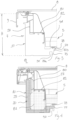
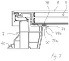
- FIG. 7 A still further embodiment of the invention is shown in Fig. 7 .
- the exposed frame surface 77 has been inclined in the embodiments shown in Figs 3-6 , it is here composed of a horizontal first section 77a adjacent to the groove 50 and a vertical second section 77b adjacent to the IGU 5.
- weather shield pane 8 is here attached to the IGU 5 rather than to the window frame 7.
Landscapes
- Engineering & Computer Science (AREA)
- Architecture (AREA)
- Civil Engineering (AREA)
- Structural Engineering (AREA)
- Securing Of Glass Panes Or The Like (AREA)
Claims (11)
- Lanterneau (1) destiné à être installé dans ou sur un toit (2) d'un bâtiment, le lanterneau (1) comprenant :un cadre de fenêtre (7) comportant quatre éléments latéraux de cadre (10) délimitant une ouverture de cadre et définissant un plan de cadre, et au moins certains desdits éléments latéraux de cadre comportant une rainure (50) conçue pour recevoir un bord d'un panneau de doublure et s'étendant dans une direction longitudinale de l'élément latéral de cadre respectif,une unité de vitrage isolante (5), abrégée UVI, reposant sur le cadre de fenêtre et couvrant l'ouverture de cadre, ladite UVI comprenant au moins deux couches translucides (5c-5e) avec un espace scellé entre elles, un gaz inerte, tel que l'argon ou le krypton, ou un vide étant présent dans le ou les espaces entre les couches translucides, etune vitre de protection contre les intempéries (3) conçue pour protéger une partie de fenêtre (4) du lanterneau (1), ladite partie de fenêtre (4) comprenant le cadre de fenêtre (7) et l'UVI (5), et ladite vitre de protection contre les intempéries étant située à une certaine distance d'un côté extérieur de l'UVI de sorte qu'un espace soit présent entre eux,le cadre de fenêtre ayant une hauteur totale (H) dans une direction de hauteur perpendiculaire au plan de cadre, et chaque élément latéral de cadre ayant une direction longitudinale s'étendant le long d'un côté périphérique (5a) de l'UVI,caractérisé en ce queune surface de cadre exposée (77) de l'élément latéral de cadre s'étend entre la rainure (50) et l'UVI (5), ladite surface de cadre exposée ayant un premier bord (771) s'étendant dans la direction longitudinale le long de la rainure et un second bord (773) s'étendant dans la direction longitudinale le long d'un côté intérieur de l'UVI, et en ce que la surface de cadre exposée (77) a une largeur totale correspondant à la distance totale entre le premier bord et le second bord mesurée le long de la surface de cadre exposée et perpendiculairement à la direction longitudinale inférieure ou égale à 40 mm.
- Lanterneau selon la revendication 1, la surface de cadre exposée étant incurvée et/ou composée de deux sections ou plus s'étendant dans le prolongement l'une de l'autre.
- Lanterneau selon la revendication 1 ou 2, la surface de cadre exposée étant inclinée par rapport à la direction de hauteur, de sorte que le second bord soit situé à une certaine distance du premier bord dans une direction parallèle au plan de cadre.
- Lanterneau selon la revendication 3, la distance entre le premier bord et le second bord dans une direction parallèle au plan de cadre étant inférieure ou égale à 15 mm.
- Lanterneau selon une ou plusieurs des revendications précédentes, chaque élément latéral de cadre comprenant une première jambe faisant saillie dans la direction de hauteur le long d'un bord de l'UVI et une seconde jambe faisant saillie sensiblement parallèlement au plan de cadre le long d'un côté intérieur de l'UVI.
- Lanterneau selon la revendication 5, chaque élément latéral de cadre comprenant une forme de section transversale ressemblant à la lettre L dans un plan s'étendant perpendiculairement à la direction longitudinale.
- Lanterneau selon la revendication 5 ou 6, l'UVI s'étendant au-delà de la rainure dans une direction parallèle au plan de cadre, de sorte que la rainure soit située sous un côté intérieur de l'UVI telle que vue dans la direction de hauteur.
- Lanterneau selon une ou plusieurs des revendications précédentes, l'UVI étant reliée au cadre de fenêtre par une liaison adhésive.
- Lanterneau selon une ou plusieurs des revendications précédentes, chaque élément latéral de cadre comprenant un profilé extrudé à chambres creuses, de préférence en polychlorure de vinyle (PVC), ou un profilé pultrudé, par exemple en polyuréthane renforcé de fibres de verre.
- Lanterneau selon une ou plusieurs des revendications précédentes, la hauteur de l'espace entre la vitre de protection contre les intempéries et l'UVI étant supérieure à la hauteur de l'UVI mesurée dans la direction de hauteur, et l'espace étant rempli d'air ambiant.
- Lanterneau selon une ou plusieurs des revendications précédentes, la surface de cadre exposée ayant une largeur totale entre le premier bord et le second bord, mesurée perpendiculairement à la direction longitudinale, inférieure ou égale à 30 % de la hauteur de cadre totale (H), par exemple inférieure ou égale à 20 % de la hauteur de cadre totale (H).
Applications Claiming Priority (1)
| Application Number | Priority Date | Filing Date | Title |
|---|---|---|---|
| EP20155247.8A EP3779090B1 (fr) | 2020-02-03 | 2020-02-03 | Un lanterneau |
Publications (4)
| Publication Number | Publication Date |
|---|---|
| EP3779094A2 EP3779094A2 (fr) | 2021-02-17 |
| EP3779094A3 EP3779094A3 (fr) | 2021-04-07 |
| EP3779094C0 EP3779094C0 (fr) | 2025-06-18 |
| EP3779094B1 true EP3779094B1 (fr) | 2025-06-18 |
Family
ID=69468360
Family Applications (2)
| Application Number | Title | Priority Date | Filing Date |
|---|---|---|---|
| EP20155247.8A Active EP3779090B1 (fr) | 2020-02-03 | 2020-02-03 | Un lanterneau |
| EP20210451.9A Active EP3779094B1 (fr) | 2020-02-03 | 2020-11-27 | Un lanterneau |
Family Applications Before (1)
| Application Number | Title | Priority Date | Filing Date |
|---|---|---|---|
| EP20155247.8A Active EP3779090B1 (fr) | 2020-02-03 | 2020-02-03 | Un lanterneau |
Country Status (2)
| Country | Link |
|---|---|
| EP (2) | EP3779090B1 (fr) |
| PL (1) | PL3779094T3 (fr) |
Families Citing this family (4)
| Publication number | Priority date | Publication date | Assignee | Title |
|---|---|---|---|---|
| BE1029229B1 (nl) * | 2021-03-22 | 2022-10-18 | Skylux N V | Dak- of raamsamenstel met inzetstuk |
| PL246599B1 (pl) * | 2022-03-03 | 2025-02-17 | Fakro Pp Spolka Z Ograniczona Odpowiedzialnoscia | Okno dachowe z pakietem szybowym |
| CN117552589B (zh) * | 2023-12-14 | 2026-04-14 | 南通万维新能源科技有限公司 | 一种排烟天窗用调节式安装结构 |
| BE1032336B1 (nl) | 2024-01-16 | 2025-08-18 | Skylux Nv | Dakraamsamenstel en kit en werkwijze voor het samenstellen van een dergelijk dakraamsamenstel |
Family Cites Families (10)
| Publication number | Priority date | Publication date | Assignee | Title |
|---|---|---|---|---|
| US4972638A (en) * | 1989-04-21 | 1990-11-27 | Rolscreen Company | Skylight flashing |
| GB2439319A (en) * | 2006-06-22 | 2007-12-27 | Metal Window Co Ltd | Rooflight comprising a water deflector |
| CN101874140B (zh) | 2007-12-20 | 2014-05-21 | Vkr控股公司 | 用于天窗的防风雨罩及其使用 |
| US20100269426A1 (en) | 2009-04-22 | 2010-10-28 | Crystalite Inc. | Glazed skylight assembly |
| GB2492380B (en) * | 2011-06-30 | 2017-01-25 | The Metal Window Co Ltd | Window thermal shield |
| GB2514119B (en) * | 2013-05-13 | 2016-09-07 | Glazing Vision Ltd | Rooflight assembly |
| EP2868831B1 (fr) * | 2013-10-31 | 2016-08-10 | JET Tageslicht und RWA GmbH | Coupole, clapet et/ou dispositif d'extraction de fumée |
| EP3101195A1 (fr) * | 2015-06-01 | 2016-12-07 | FAKRO PP Sp. z o.o. | Fenêtre de toit avec ensemble vitré |
| EP3346071B1 (fr) * | 2017-01-06 | 2021-03-10 | VKR Holding A/S | Ensemble de fenêtre |
| PL126314U1 (pl) * | 2017-04-28 | 2018-11-05 | Ryszard Florek | Okno dachów płaskich z osłoną zewnętrzną |
-
2020
- 2020-02-03 EP EP20155247.8A patent/EP3779090B1/fr active Active
- 2020-11-27 PL PL20210451.9T patent/PL3779094T3/pl unknown
- 2020-11-27 EP EP20210451.9A patent/EP3779094B1/fr active Active
Also Published As
| Publication number | Publication date |
|---|---|
| EP3779090A1 (fr) | 2021-02-17 |
| EP3779094A2 (fr) | 2021-02-17 |
| EP3779094C0 (fr) | 2025-06-18 |
| EP3779090B1 (fr) | 2025-09-10 |
| EP3779094A3 (fr) | 2021-04-07 |
| PL3779094T3 (pl) | 2025-07-28 |
Similar Documents
| Publication | Publication Date | Title |
|---|---|---|
| EP3779094B1 (fr) | Un lanterneau | |
| EP3911830B1 (fr) | Couvercle d'ouverture muni d'une unité de vig se chevauchant et profilé de raccordement raccordé à un élément de cadre structural | |
| US6401428B1 (en) | Fenestration sealed frame, insulating glazing panels | |
| US8943769B2 (en) | Pane module for use in a window | |
| EP3795770B1 (fr) | Lucarne de toit | |
| CA1196763A (fr) | Lucarne d'aeration | |
| EP2318634B1 (fr) | Membrane d'étanchéité pour étanchéifier les espaces entre des encadrements de fenêtre et des ouvertures brutes | |
| US4570394A (en) | Ventilating skylight | |
| WO2021156313A1 (fr) | Fenêtre de toit | |
| EP3563015A1 (fr) | Module de vitre conçu pour être installé sur un cadre de fenêtre et procédé de fabrication de module de vitre | |
| CN100419202C (zh) | 一种包括带有板单元的框架的板件 | |
| EP3779088B1 (fr) | Fenêtre de toit ayant une unité de vitrage isolant près du cadre de la fenêtre | |
| US5993925A (en) | Protective windows for ornamental windows | |
| EP3795771B1 (fr) | Lucarne de toit | |
| EP3779093B1 (fr) | Une lucarne | |
| CN214785206U (zh) | 一种密封垫圈和一种面板系统 | |
| EP3859093A1 (fr) | Cadre adaptateur pour installer une fenêtre du jour, système comprenant une fenêtre du jour et procédé d'installation d'une et procédés à l'aide d'un cadre adaptateur | |
| CN113802749A (zh) | 在包括多个面板的面板系统中使用的面板及其制造方法 | |
| CN113802779A (zh) | 包括具有包围镶板元件的型材元件的面板的面板系统 | |
| CN113802781A (zh) | 具有带有安装型材和铰链的安装和铰链组件的面板系统 | |
| JP2002089149A (ja) | 開閉窓の取付構造 | |
| CA2414589A1 (fr) | Puits de lumiere |
Legal Events
| Date | Code | Title | Description |
|---|---|---|---|
| PUAI | Public reference made under article 153(3) epc to a published international application that has entered the european phase |
Free format text: ORIGINAL CODE: 0009012 |
|
| STAA | Information on the status of an ep patent application or granted ep patent |
Free format text: STATUS: THE APPLICATION HAS BEEN PUBLISHED |
|
| AK | Designated contracting states |
Kind code of ref document: A2 Designated state(s): AL AT BE BG CH CY CZ DE DK EE ES FI FR GB GR HR HU IE IS IT LI LT LU LV MC MK MT NL NO PL PT RO RS SE SI SK SM TR |
|
| AX | Request for extension of the european patent |
Extension state: BA ME |
|
| PUAL | Search report despatched |
Free format text: ORIGINAL CODE: 0009013 |
|
| AK | Designated contracting states |
Kind code of ref document: A3 Designated state(s): AL AT BE BG CH CY CZ DE DK EE ES FI FR GB GR HR HU IE IS IT LI LT LU LV MC MK MT NL NO PL PT RO RS SE SI SK SM TR |
|
| AX | Request for extension of the european patent |
Extension state: BA ME |
|
| RIC1 | Information provided on ipc code assigned before grant |
Ipc: E04D 13/03 20060101AFI20210304BHEP Ipc: E04D 13/035 20060101ALI20210304BHEP |
|
| STAA | Information on the status of an ep patent application or granted ep patent |
Free format text: STATUS: REQUEST FOR EXAMINATION WAS MADE |
|
| 17P | Request for examination filed |
Effective date: 20211007 |
|
| RBV | Designated contracting states (corrected) |
Designated state(s): AL AT BE BG CH CY CZ DE DK EE ES FI FR GB GR HR HU IE IS IT LI LT LU LV MC MK MT NL NO PL PT RO RS SE SI SK SM TR |
|
| STAA | Information on the status of an ep patent application or granted ep patent |
Free format text: STATUS: EXAMINATION IS IN PROGRESS |
|
| 17Q | First examination report despatched |
Effective date: 20241017 |
|
| GRAP | Despatch of communication of intention to grant a patent |
Free format text: ORIGINAL CODE: EPIDOSNIGR1 |
|
| STAA | Information on the status of an ep patent application or granted ep patent |
Free format text: STATUS: GRANT OF PATENT IS INTENDED |
|
| INTG | Intention to grant announced |
Effective date: 20250203 |
|
| GRAS | Grant fee paid |
Free format text: ORIGINAL CODE: EPIDOSNIGR3 |
|
| GRAA | (expected) grant |
Free format text: ORIGINAL CODE: 0009210 |
|
| STAA | Information on the status of an ep patent application or granted ep patent |
Free format text: STATUS: THE PATENT HAS BEEN GRANTED |
|
| AK | Designated contracting states |
Kind code of ref document: B1 Designated state(s): AL AT BE BG CH CY CZ DE DK EE ES FI FR GB GR HR HU IE IS IT LI LT LU LV MC MK MT NL NO PL PT RO RS SE SI SK SM TR |
|
| REG | Reference to a national code |
Ref country code: GB Ref legal event code: FG4D |
|
| REG | Reference to a national code |
Ref country code: CH Ref legal event code: EP |
|
| REG | Reference to a national code |
Ref country code: DE Ref legal event code: R096 Ref document number: 602020052862 Country of ref document: DE |
|
| REG | Reference to a national code |
Ref country code: CH Ref legal event code: EP |
|
| REG | Reference to a national code |
Ref country code: IE Ref legal event code: FG4D |
|
| U01 | Request for unitary effect filed |
Effective date: 20250709 |
|
| U07 | Unitary effect registered |
Designated state(s): AT BE BG DE DK EE FI FR IT LT LU LV MT NL PT RO SE SI Effective date: 20250716 |
|
| PG25 | Lapsed in a contracting state [announced via postgrant information from national office to epo] |
Ref country code: NO Free format text: LAPSE BECAUSE OF FAILURE TO SUBMIT A TRANSLATION OF THE DESCRIPTION OR TO PAY THE FEE WITHIN THE PRESCRIBED TIME-LIMIT Effective date: 20250918 Ref country code: GR Free format text: LAPSE BECAUSE OF FAILURE TO SUBMIT A TRANSLATION OF THE DESCRIPTION OR TO PAY THE FEE WITHIN THE PRESCRIBED TIME-LIMIT Effective date: 20250919 |
|
| PG25 | Lapsed in a contracting state [announced via postgrant information from national office to epo] |
Ref country code: HR Free format text: LAPSE BECAUSE OF FAILURE TO SUBMIT A TRANSLATION OF THE DESCRIPTION OR TO PAY THE FEE WITHIN THE PRESCRIBED TIME-LIMIT Effective date: 20250618 |
|
| PG25 | Lapsed in a contracting state [announced via postgrant information from national office to epo] |
Ref country code: RS Free format text: LAPSE BECAUSE OF FAILURE TO SUBMIT A TRANSLATION OF THE DESCRIPTION OR TO PAY THE FEE WITHIN THE PRESCRIBED TIME-LIMIT Effective date: 20250918 |
|
| U20 | Renewal fee for the european patent with unitary effect paid |
Year of fee payment: 6 Effective date: 20251008 |
|
| PG25 | Lapsed in a contracting state [announced via postgrant information from national office to epo] |
Ref country code: IS Free format text: LAPSE BECAUSE OF FAILURE TO SUBMIT A TRANSLATION OF THE DESCRIPTION OR TO PAY THE FEE WITHIN THE PRESCRIBED TIME-LIMIT Effective date: 20251018 |
|
| PGFP | Annual fee paid to national office [announced via postgrant information from national office to epo] |
Ref country code: GB Payment date: 20251016 Year of fee payment: 6 |
|
| PG25 | Lapsed in a contracting state [announced via postgrant information from national office to epo] |
Ref country code: SM Free format text: LAPSE BECAUSE OF FAILURE TO SUBMIT A TRANSLATION OF THE DESCRIPTION OR TO PAY THE FEE WITHIN THE PRESCRIBED TIME-LIMIT Effective date: 20250618 |
|
| PG25 | Lapsed in a contracting state [announced via postgrant information from national office to epo] |
Ref country code: CZ Free format text: LAPSE BECAUSE OF FAILURE TO SUBMIT A TRANSLATION OF THE DESCRIPTION OR TO PAY THE FEE WITHIN THE PRESCRIBED TIME-LIMIT Effective date: 20250618 |
|
| PGFP | Annual fee paid to national office [announced via postgrant information from national office to epo] |
Ref country code: PL Payment date: 20251014 Year of fee payment: 6 |
|
| PG25 | Lapsed in a contracting state [announced via postgrant information from national office to epo] |
Ref country code: SK Free format text: LAPSE BECAUSE OF FAILURE TO SUBMIT A TRANSLATION OF THE DESCRIPTION OR TO PAY THE FEE WITHIN THE PRESCRIBED TIME-LIMIT Effective date: 20250618 |
|
| PG25 | Lapsed in a contracting state [announced via postgrant information from national office to epo] |
Ref country code: ES Free format text: LAPSE BECAUSE OF FAILURE TO SUBMIT A TRANSLATION OF THE DESCRIPTION OR TO PAY THE FEE WITHIN THE PRESCRIBED TIME-LIMIT Effective date: 20250618 |
|
| PLBE | No opposition filed within time limit |
Free format text: ORIGINAL CODE: 0009261 |
|
| STAA | Information on the status of an ep patent application or granted ep patent |
Free format text: STATUS: NO OPPOSITION FILED WITHIN TIME LIMIT |