EP3779102B1 - Dispositif de protection contre le rayonnement solaire et/ou les précipitations - Google Patents
Dispositif de protection contre le rayonnement solaire et/ou les précipitations Download PDFInfo
- Publication number
- EP3779102B1 EP3779102B1 EP20185924.6A EP20185924A EP3779102B1 EP 3779102 B1 EP3779102 B1 EP 3779102B1 EP 20185924 A EP20185924 A EP 20185924A EP 3779102 B1 EP3779102 B1 EP 3779102B1
- Authority
- EP
- European Patent Office
- Prior art keywords
- roof tarpaulin
- frame
- tarpaulin
- roof
- transverse
- Prior art date
- Legal status (The legal status is an assumption and is not a legal conclusion. Google has not performed a legal analysis and makes no representation as to the accuracy of the status listed.)
- Active
Links
Images


Classifications
-
- E—FIXED CONSTRUCTIONS
- E04—BUILDING
- E04H—BUILDINGS OR LIKE STRUCTURES FOR PARTICULAR PURPOSES; SWIMMING OR SPLASH BATHS OR POOLS; MASTS; FENCING; TENTS OR CANOPIES, IN GENERAL
- E04H15/00—Tents or canopies, in general
- E04H15/003—Bathing or beach cabins
-
- E—FIXED CONSTRUCTIONS
- E04—BUILDING
- E04H—BUILDINGS OR LIKE STRUCTURES FOR PARTICULAR PURPOSES; SWIMMING OR SPLASH BATHS OR POOLS; MASTS; FENCING; TENTS OR CANOPIES, IN GENERAL
- E04H15/00—Tents or canopies, in general
- E04H15/32—Parts, components, construction details, accessories, interior equipment, specially adapted for tents, e.g. guy-line equipment, skirts, thresholds
- E04H15/58—Closures; Awnings; Sunshades
-
- E—FIXED CONSTRUCTIONS
- E04—BUILDING
- E04H—BUILDINGS OR LIKE STRUCTURES FOR PARTICULAR PURPOSES; SWIMMING OR SPLASH BATHS OR POOLS; MASTS; FENCING; TENTS OR CANOPIES, IN GENERAL
- E04H15/00—Tents or canopies, in general
- E04H15/003—Bathing or beach cabins
- E04H15/005—Wind breakers, i.e. fabric stretched between posts anchored in the ground
-
- E—FIXED CONSTRUCTIONS
- E04—BUILDING
- E04H—BUILDINGS OR LIKE STRUCTURES FOR PARTICULAR PURPOSES; SWIMMING OR SPLASH BATHS OR POOLS; MASTS; FENCING; TENTS OR CANOPIES, IN GENERAL
- E04H15/00—Tents or canopies, in general
- E04H15/02—Tents combined or specially associated with other devices
- E04H15/10—Heating, lighting or ventilating
- E04H15/14—Ventilating
- E04H15/16—Ventilating of tent roofs
Definitions
- the invention relates to a device for protection against solar radiation and/or precipitation, with a roof tarpaulin and a first frame, the roof tarpaulin having two opposite transverse sides extending in a transverse direction of the roof tarpaulin and two longitudinal sides connecting the transverse sides and extending in a longitudinal direction of the roof tarpaulin a first of the transverse sides forms first fastening means for fastening to a substrate and the second of the transverse sides forms second fastening means for fastening the roof tarpaulin to the first frame in such a way that the first frame supports the transverse side fastened to it at least in a section of the transverse direction of the roof tarpaulin, having.
- Such a device is from US 9,051,756 B1 famous.
- the roof tarpaulin which extends between the first frame and the ground, is prevented from collapsing in that it is aligned in such a way that an air flow (wind) from the second transverse side attached to the first frame under the roof tarpaulin flows and this inflates as a result of the attachment of the first transverse side to the ground.
- the U.S. 3,075,536 A further discloses a beach tent according to the preamble of claim 1, in which a plurality of eyelets are provided along the two longitudinal sides of the roof tarpaulin, through which a rope is threaded to shorten the longitudinal sides.
- Other devices to protect against solar radiation are from the U.S. 3,404,696 A and the U.S. Patent No. 5,080,123 famous.
- the object of the invention is to prevent the flapping movement of the roof tarpaulin by means of a targeted and, in particular, reproducible folding of the roof tarpaulin on the longitudinal sides.
- a device for protection against solar radiation and/or precipitation which comprises at least one roof tarpaulin and a first frame, the roof tarpaulin having two transverse sides that are at least partially opposite one another and extend in a transverse direction of the roof tarpaulin, as well as two transverse sides that connect and are longitudinal sides extending in a longitudinal direction of the roof tarpaulin.
- a first of the transverse sides has first fastening means for fastening to a substrate and the second of the transverse sides has second fastening means for fastening the roof tarpaulin to the first frame, this fastening of the roof tarpaulin to the first frame being designed or provided in such a way that the first frame supports the transverse side attached thereto at least in a section of the transverse direction of the roof tarpaulin.
- such a device is further characterized by shortening means for shortening the free edge length of the longitudinal sides of the roof tarpaulin as required, preferably reversible, with the roof tarpaulin forming at least one pocket on the longitudinal sides that ends in the respective edge of the roof tarpaulin.
- edge length is understood to mean the length of the edge that delimits the web of material of the roof tarpaulin on the respective longitudinal side.
- the “free edge length” is then the portion of the edge length that results from a roof tarpaulin spread out in a plane as the course of the edge lying in this plane. If the shortening agent is not effective, the free edge length correspond in particular to the actual edge length, while the free edge length is shorter than the actual edge length when the shortening means is effective.
- the roof tarpaulin is forced into a curvature along the transverse direction in a state inflated by an air flow (especially wind), which leads to a permanent tensioning of the shortened longitudinal sides, whereby a fluttering movement of the roof tarpaulin is effectively prevented.
- the shortening means can preferably each comprise two connecting elements (e.g. straps or (press) buttons) which are spaced apart in the longitudinal direction of the roof tarpaulin and which are preferably detachably connectable or connected to one another.
- the shortening means can then be used in particular to fix a fold in the respective longitudinal side of the roof tarpaulin, as a result of which a part of the edge of the respective longitudinal side forms a loop. This loop-shaped part of the edge is then no longer part of the free edge length of the respective edge.
- the pockets enable a targeted and, in particular, reproducible folding of the roof tarpaulin on the long sides.
- Such a pocket represents a depression in relation to the adjoining sections of the roof tarpaulin, even if the shortening means are not effective. This applies in particular if the roof tarpaulin is held taut in such a way that, with the exception of at least the pockets, it runs in one plane.
- the roof tarpaulin has one or more passage openings in the half that includes the first transverse side. Provision can furthermore preferably be made for the through-opening or at least some of the through-openings to be closable, for example by means of a roll-up closing tarpaulin which, if necessary, is spread out over one or more of the through-openings and, if necessary, in this spread-out position on the roof tarpaulin, for example can be fixed.
- this makes it possible to close the passage opening(s) as required, in order to ensure reliable inflation of the roof tarpaulin even with a relatively weak air flow.
- a closed passage opening also prevents the ingress of solar radiation and/or precipitation, so that the most comprehensive protection possible is then provided underneath the roof tarpaulin.
- the roof tarpaulin has third fastening means in a central section for fastening the roof tarpaulin to the first frame or to a second frame in such a way that this frame covers the central section at least in a section of the transverse direction of the roof tarpaulin supports, has.
- the first frame is fastened to the roof tarpaulin in the central section by means of the third fastening means and thereby stretches it in the transverse direction, while the first transverse side and the second transverse side are fastened to the substructure via the (first and second) fastening means there will.
- the roof tarpaulin is stretched in a tent-like form, which is stable even without an inflow of air flow.
- the second frame is fastened to the roof tarpaulin in the central section by means of the third fastening means and that the first transverse side is fastened to the substructure by means of the first fastening means there and the second transverse side is fastened to the first frame by means of the second fastening means there.
- the first frame and/or the second frame has a cross member and at least one support, which can preferably be releasably connected to one another.
- the support has one end with a T-piece, that the cross member comprises two cross member parts that can each be inserted into an open end of the T-piece and that the second fastening means and/or the third fastening means (if present) comprise two tube sections of the roof tarpaulin, which are preferably arranged coaxially and spaced apart from one another and into which the cross member parts can be inserted.
- Such a frame is sufficiently stable, easy to set up and dismantle and, due to the relatively small number of frame supports, is relatively light and takes up only a small packing volume. This ensures advantageous transport and space-saving storage of the device when not in use.
- the ends of the tube sections of the roof tarpaulin located on the transverse sides are closed and that the transverse support parts each have a releasable locking element which is designed to be in a locking position at the adjacent end of the T -piece to fit.
- This allows the roof tarpaulin to be fixed to the first frame once the cross member parts of the first frame have been inserted into the tube sections of the roof tarpaulin and into the open ends of the T-piece and the locking elements in their locking positions at the respective ends of the T-piece issue.
- the closed ends of the tube sections of the roof tarpaulin then prevent the roof tarpaulin from being displaced laterally, i.e. in the direction of the transverse side of the roof tarpaulin, relative to the first frame. At the same time, the cross member parts of the first frame can no longer be pulled out of the T-piece.
- the locking elements can furthermore preferably be inserted into a support tube of the respective cross member part with increasing prestressing of a spring element be pressed, which allows the simplest possible assembly and disassembly of the first frame and thus the device.
- the first frame and in particular the support of the first frame has a preferably disc-shaped holding element which has one or more hooks and/or one or more depressions, in particular in the form of through-openings.
- a holding element can be used, in particular in connection with a fastening cable, to fasten the first frame to the ground.
- any objects, such as items of clothing can be hung on such a holding element.
- a device can also preferably comprise a wall tarpaulin, which is set up for attachment to the first frame and/or the roof tarpaulin in an orientation extending from the ground towards the roof tarpaulin.
- the wall tarpaulin can preferably extend from the ground to the roof tarpaulin or end in front of the roof tarpaulin, so that a free space remains between an upper edge of the wall tarpaulin and the corresponding transverse side of the roof tarpaulin, which can also serve the purpose, for example, of preventing an inflow of To allow air flow with the aim of inflating the roof tarpaulin.
- the roof tarpaulin has connecting means on the first transverse side and/or on the second transverse side for connection to connecting means of an in particular identical, second device.
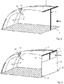
- the devices according to the invention shown in the drawings each comprise a substantially rectangular roof tarpaulin 1 and at least one first frame 2, the roof tarpaulin 1 having two opposite transverse sides extending in a transverse direction of the roof tarpaulin 1 and two connecting the transverse sides and extending in a longitudinal direction of the Roof tarpaulin 1 forms extending longitudinal sides.
- a first of the transverse sides has first fastening means, for example in the form of eyelets or loops integrated into the roof tarpaulin 1, by means of which, for example in connection with corresponding ground anchors, the first transverse side of the roof tarpaulin 1 can be fastened to a substrate 3.
- the second of the transverse sides comprises second fastening means, by means of which the roof tarpaulin 1 can be fastened to the first frame 2 in such a way that the first frame 2 supports the second transverse side fastened thereto essentially along the entire transverse direction of the roof tarpaulin 1 .
- These second fastening means comprise two tube sections (not shown) extending in coaxial alignment along the transverse direction of the roof tarpaulin, between which a distance is provided in a central section with respect to the transverse direction of the roof tarpaulin 1 . The ends of these tube sections located on or near the longitudinal sides are closed, while the ends of the tube sections facing one another are open.
- two cross member parts 4 of the first frame are first pushed into one of the tube sections of the roof tarpaulin 1 until they abut the closed ends of the tube sections. Then a T-piece 5 of the first frame 2 is pushed with one of its open ends onto a first (4a) of the cross member parts 4 and pushed onto this first cross member part 4a far enough that it is possible to insert the adjoining end of the second cross member part 4b into the opposite open end of the T-piece 5 to insert.
- This design of the first frame 2 in combination with the closed ends of the tube sections on the long sides of the roof tarpaulin 1 means that the cross member parts 4 cannot be pulled out of the T-piece 5 unintentionally when the device is installed and at the same time means that the roof tarpaulin 1 is held securely is connected to the first frame 2.
- the roof tarpaulin 1 has a relatively large passage opening 8 in the half comprising the first transverse side extends to the first transverse side.
- this relatively large passage opening 8 more (specifically three) smaller, arranged in a horizontal row through-openings 8 are provided, if necessary by means of a closure tarpaulin 9, with one of its edges with the Roof tarpaulin 1 is connected, can be closed.
- an outflow of air flow that has flowed under the roof tarpaulin 1 can be influenced in a targeted manner and thus, depending on the strength of the air flow, a reliable inflation of the roof tarpaulin 1 can be achieved and at the same time an overloading of the device by the air flow can be avoided.
- the device comprises shortening means 10 for reversibly shortening the free edge length of the longitudinal sides of the roof tarpaulin 1.
- These shortening means 10 each comprise two connecting means in the form of spaced apart in the longitudinal direction of the roof tarpaulin 1 Straps 11, which can be connected to one another by a loop or a knot, as a result of which the roof tarpaulin 1 forms a loop-shaped fold, with each of these folds - in the manner of a gathering of the roof tarpaulin at the edge - shortening the free edge length of the long sides of the roof tarpaulin 1 is realized.
- the straps 11 serving as connecting means are connected to the roof tarpaulin 1 in the area of the pocket surfaces 13 .
- a device according to the invention can also comprise a wall tarpaulin 14 intended to be connected to the first frame 2 as well as to the substructure 3 in an orientation extending from the substructure 3 to the roof tarpaulin 1.
- This wall tarpaulin 14 is used, for example, to protect a person behind it from (wind) and from correspondingly obliquely incident solar radiation and obliquely incident precipitation.
- a guide cable 15 extends from the free ends of the cross member parts 4 of the first frame 2 or from the roof tarpaulin 1 to the substrate 3, on which the Wall tarpaulin 14 is attached in each case.
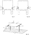
- a support 16 of the first frame 2, onto the upper end of which the T-piece 5 is attached comprises a holding element 17 in the form of a ring disk (cf. Figures 4 and 5 ), in which several passage openings 18 are introduced.
- a fastening cable 19 can (respectively) be attached to one or more of the passage openings 18 , which can be fastened to the substructure 3 with its other end via a ground anchor 20 .
- the holding element 17 can also be used to hang up objects (not shown).
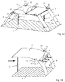
- the 8 and 11 to 13 show alternative types of construction of devices according to the invention, which enable the associated roof tarpaulin 1 to be stretched out with a sufficiently large free space below the roof tarpaulin 1, especially when there is no wind.
- the roof tarpaulin 1 is fastened to the substrate 3 both in the area of the first transverse side and the second transverse side, for which purpose the roof tarpaulin 1 can have corresponding additional fastening means (not shown), for example in the form of eyelets or loops, in the area of the second transverse side.
- the roof tarpaulin 1 comprises third fastening means (not shown) in a central section, which in particular can be functionally identical to the second fastening means and which can therefore also have two tube sections into which the cross member parts 1 of a first frame 2 can be inserted.
- tent-like stretching of the roof tarpaulin 1 is realized by means of a single first frame 2 .
- the first frame 2a as previously based on, inter alia, the Figures 1, 2 and 11 described in the field of second transverse side is connected to the second fastening means
- the second frame 2b as previously based on the 8 described, is connected in a central section of the roof tarpaulin 1 with the third fastening means present there.
- This type of construction is similar to that according to FIGS Figures 1, 2 and 13 , i.e. the second transverse side of the roof tarpaulin 1, which is supported by the first frame 2a, is located well above the subsurface 3.
- the two roof tarpaulins 1 are each connected to one another in a central section with an associated first frame 2 and in the area of the respective second transverse side by means of connecting means, for which purpose straps 11 can be used, for example, which are provided by the respective on the second transverse sides of the roof tarpaulin 1, additional fasteners in the form of eyelets or loops out and knotted or connected by means of loops.
- Pockets 12 of the shortening means 10 shown have a triangular shape in plan view, while the pockets 12 in the exemplary embodiments of FIG Figures 8 to 13 are approximately semicircular. It is particularly advantageous if only one continuous band 11 is provided in the region of each semicircular pocket, which is guided in a semicircular sewn-in section of the roof tarpaulin. Pulling together and knotting the two ends of the strap 11 then not only shortens the edges running in the longitudinal direction of the roof tarpaulin, but also causes a shortening in the transverse direction, which reduces the area of the roof tarpaulin and increases wind stability.
Landscapes
- Engineering & Computer Science (AREA)
- Architecture (AREA)
- Civil Engineering (AREA)
- Structural Engineering (AREA)
- Tents Or Canopies (AREA)
Claims (13)
- Dispositif de protection contre le rayonnement solaire et/ou les précipitations, ledit dispositif comprenant une bâche de toit (1) et un premier support (2), où la bâche de toit forme deux côtés transversaux opposés et s'étendant dans une direction transversale de la bâche de toit et deux côtés longitudinaux reliant les côtés transversaux et s'étendant dans une direction longitudinale de la bâche de toit (1), où un premier des côtés transversaux présente des premiers moyens de fixation servant à la fixation sur un fond (3), et le second des côtés transversaux présente des deuxièmes moyens de fixation pour une fixation de la bâche de toit (1) sur le premier support (2), de manière telle que le premier support (2) soutienne le côté transversal fixé sur ledit premier support au moins dans une partie de la direction transversale de la bâche de toit (1), où des moyens de raccourcissement (10) sont prévus pour servir au raccourcissement de la longueur de bord libre des côtés longitudinaux,
caractérisé en ce que la bâche de toit (1) forme à chaque fois, au niveau des côtés longitudinaux, au moins une poche (12) se terminant dans le bord respectif de la bâche de toit (1). - Dispositif selon la revendication 1, caractérisé en ce que les moyens de raccourcissement (10) comprennent à chaque fois deux éléments d'assemblage disposés en étant espacés dans la direction longitudinale de la bâche de toit, éléments d'assemblage qui peuvent être reliés ou sont reliés l'un à l'autre.
- Dispositif selon l'une des revendications précédentes, caractérisé en ce que la bâche de toit (1) présente une ou plusieurs ouvertures de passage (8) se trouvant dans la moitié comprenant le premier côté transversal.
- Dispositif selon la revendication 3, caractérisé en ce que l'ouverture de passage (8) ou au moins certaines des ouvertures de passage (8) peut ou peuvent être fermée(s).
- Dispositif selon l'une quelconque des revendications précédentes, caractérisé en ce que la bâche de toit (1) présente, dans une partie centrale, des troisièmes moyens de fixation pour une fixation de la bâche de toit (1) sur le premier support (2a) ou sur un second support (2b), de manière telle que le premier support (2a) ou le second support (2b) soutienne la partie centrale de la bâche de toit (1), au moins dans une partie de la direction transversale de la bâche de toit (1).
- Dispositif selon la revendication 5, caractérisé en ce que le premier support (2a) et/ou le second support (2b) présente une transverse et au moins un montant (16) qui peut être relié à la traverse de manière amovible.
- Dispositif selon la revendication 6, caractérisé en ce que :- le montant (16) présente une extrémité comprenant une pièce (5) en T,- la traverse comprend deux parties de traverse (4) qui à chaque fois peuvent être insérées par glissement dans une extrémité ouverte de la pièce (5) en T, et- les deuxièmes moyens de fixation et/ou les troisièmes moyens de fixation comprennent deux tronçons de tube de la bâche de toit (1), tronçons de tube dans lesquels les parties de traverse (4) peuvent être insérées par glissement.
- Dispositif selon la revendication 7, caractérisé en ce que les extrémités des tronçons de tube, qui sont situées sur les côtés longitudinaux de la bâche de toit (1), sont fermées, et en ce que les parties de traverse (4) présentent à chaque fois un élément de verrouillage amovible (6) qui est monté afin d'être contigu, dans une position de verrouillage, à l'extrémité adjacente de la pièce (5) en T.
- Dispositif selon la revendication 8, caractérisé en ce que l'élément de verrouillage (6), sous l'effet d'une précontrainte croissante d'un élément faisant ressort, peut être poussé dans un tube porteur (7) de la partie de traverse respective (4).
- Dispositif selon l'une quelconque des revendications 6 à 9, caractérisé en ce que le montant (16) présente un élément de retenue (17) qui présente des crochets ou des creux (18).
- Dispositif selon l'une quelconque des revendications précédentes, caractérisé par une bâche murale (14) qui, pour la fixation sur le premier support (2) ou sur la bâche de toit (1), est installée suivant une orientation s'étendant depuis le fond (3) en direction de la bâche de toit (1).
- Dispositif selon l'une quelconque des revendications précédentes, caractérisé en ce que la bâche de toit (1) présente sur le premier côté transversal et/ou sur le second côté transversal des moyens d'assemblage servant à l'assemblage avec des moyens d'assemblage d'un second dispositif.
- Combinaison de deux dispositifs selon la revendication 12.
Applications Claiming Priority (1)
| Application Number | Priority Date | Filing Date | Title |
|---|---|---|---|
| DE202019104428.4U DE202019104428U1 (de) | 2019-08-12 | 2019-08-12 | Vorrichtung zum Schutz vor Sonnenstrahlung und/oder Niederschlag |
Publications (2)
| Publication Number | Publication Date |
|---|---|
| EP3779102A1 EP3779102A1 (fr) | 2021-02-17 |
| EP3779102B1 true EP3779102B1 (fr) | 2022-04-27 |
Family
ID=68105490
Family Applications (1)
| Application Number | Title | Priority Date | Filing Date |
|---|---|---|---|
| EP20185924.6A Active EP3779102B1 (fr) | 2019-08-12 | 2020-07-15 | Dispositif de protection contre le rayonnement solaire et/ou les précipitations |
Country Status (3)
| Country | Link |
|---|---|
| EP (1) | EP3779102B1 (fr) |
| DE (1) | DE202019104428U1 (fr) |
| ES (1) | ES2913709T3 (fr) |
Families Citing this family (1)
| Publication number | Priority date | Publication date | Assignee | Title |
|---|---|---|---|---|
| US12054961B2 (en) * | 2023-10-19 | 2024-08-06 | Xianrui Zeng | Beach sunshade |
Family Cites Families (5)
| Publication number | Priority date | Publication date | Assignee | Title |
|---|---|---|---|---|
| US3075536A (en) * | 1959-12-09 | 1963-01-29 | George B D Parker | Beach tent |
| US3404696A (en) * | 1967-01-25 | 1968-10-08 | Alcantara Machada R | Beach tent |
| US5080123A (en) * | 1991-04-15 | 1992-01-14 | Peter Stein | Sun shield assembly |
| US9051756B1 (en) | 2011-10-18 | 2015-06-09 | John D. Jenkins | Collapsible sunshade |
| GB2573353B (en) * | 2018-10-29 | 2020-11-25 | Osborne Mark | Portable sun shades |
-
2019
- 2019-08-12 DE DE202019104428.4U patent/DE202019104428U1/de not_active Expired - Lifetime
-
2020
- 2020-07-15 ES ES20185924T patent/ES2913709T3/es active Active
- 2020-07-15 EP EP20185924.6A patent/EP3779102B1/fr active Active
Also Published As
| Publication number | Publication date |
|---|---|
| EP3779102A1 (fr) | 2021-02-17 |
| ES2913709T3 (es) | 2022-06-03 |
| DE202019104428U1 (de) | 2019-09-17 |
Similar Documents
| Publication | Publication Date | Title |
|---|---|---|
| DE2353599A1 (de) | Zelt | |
| DE2652519A1 (de) | Campingzelt fuer kraftrad- und radfahrer | |
| EP3779102B1 (fr) | Dispositif de protection contre le rayonnement solaire et/ou les précipitations | |
| EP0465430B1 (fr) | Couverture de piscine | |
| EP3372754B1 (fr) | Auvent pour véhicule, en particulier pour une caravane ou un camping-car | |
| DE2453085C2 (de) | Zusammenlegbare Schutzhülle | |
| DE60312939T2 (de) | Abdeckungselement für Behälter oder dergleichen | |
| EP1892357A2 (fr) | Auvent pour caravanes | |
| DE202010015106U1 (de) | Schirmsegel | |
| EP2710577B1 (fr) | Structure porteuse pour espace publicitaire et support publicitaire muni d'une telle structure porteuse | |
| DE102023111498A1 (de) | Rollosystem | |
| DE102006051617B4 (de) | Vorzelt für einen Campingwagen | |
| DE9210803U1 (de) | Rolldach | |
| DE10040581A1 (de) | Zeltdach für Terrassen | |
| AT241288B (de) | Zeltgarage für Kraftfahrzeuge | |
| DE102021105007A1 (de) | Abnehmbare Fahrzeugtür | |
| DE29612221U1 (de) | Verebenbares, leichtes Biwakzelt, dessen Tuch als Sonnensegel oder Regenplane dient | |
| DE202012005772U1 (de) | Volant und Markise | |
| DE202005018040U1 (de) | Vorzelt für einen Campingwagen | |
| EP0589400A1 (fr) | Tente | |
| DE102020134864A1 (de) | Automatisiertes zusammenfaltbares Abdecksystem für Schwimmbecken | |
| DE29812158U1 (de) | Kabine zum Schutz von Personen gegen Witterungseinflüsse | |
| DE1434721A1 (de) | Faltgaragen | |
| DE10218906A1 (de) | Überdachungssystem für Sitzgarnituren | |
| DE2527382B2 (de) | Schutzabdeckung für verschwenkbare Dachflächenfenster |
Legal Events
| Date | Code | Title | Description |
|---|---|---|---|
| PUAI | Public reference made under article 153(3) epc to a published international application that has entered the european phase |
Free format text: ORIGINAL CODE: 0009012 |
|
| STAA | Information on the status of an ep patent application or granted ep patent |
Free format text: STATUS: THE APPLICATION HAS BEEN PUBLISHED |
|
| AK | Designated contracting states |
Kind code of ref document: A1 Designated state(s): AL AT BE BG CH CY CZ DE DK EE ES FI FR GB GR HR HU IE IS IT LI LT LU LV MC MK MT NL NO PL PT RO RS SE SI SK SM TR |
|
| AX | Request for extension of the european patent |
Extension state: BA ME |
|
| STAA | Information on the status of an ep patent application or granted ep patent |
Free format text: STATUS: REQUEST FOR EXAMINATION WAS MADE |
|
| 17P | Request for examination filed |
Effective date: 20210622 |
|
| RBV | Designated contracting states (corrected) |
Designated state(s): AL AT BE BG CH CY CZ DE DK EE ES FI FR GB GR HR HU IE IS IT LI LT LU LV MC MK MT NL NO PL PT RO RS SE SI SK SM TR |
|
| GRAP | Despatch of communication of intention to grant a patent |
Free format text: ORIGINAL CODE: EPIDOSNIGR1 |
|
| STAA | Information on the status of an ep patent application or granted ep patent |
Free format text: STATUS: GRANT OF PATENT IS INTENDED |
|
| INTG | Intention to grant announced |
Effective date: 20211122 |
|
| GRAS | Grant fee paid |
Free format text: ORIGINAL CODE: EPIDOSNIGR3 |
|
| GRAA | (expected) grant |
Free format text: ORIGINAL CODE: 0009210 |
|
| STAA | Information on the status of an ep patent application or granted ep patent |
Free format text: STATUS: THE PATENT HAS BEEN GRANTED |
|
| AK | Designated contracting states |
Kind code of ref document: B1 Designated state(s): AL AT BE BG CH CY CZ DE DK EE ES FI FR GB GR HR HU IE IS IT LI LT LU LV MC MK MT NL NO PL PT RO RS SE SI SK SM TR |
|
| REG | Reference to a national code |
Ref country code: GB Ref legal event code: FG4D Free format text: NOT ENGLISH |
|
| REG | Reference to a national code |
Ref country code: CH Ref legal event code: EP |
|
| REG | Reference to a national code |
Ref country code: AT Ref legal event code: REF Ref document number: 1487047 Country of ref document: AT Kind code of ref document: T Effective date: 20220515 |
|
| REG | Reference to a national code |
Ref country code: DE Ref legal event code: R096 Ref document number: 502020001000 Country of ref document: DE |
|
| REG | Reference to a national code |
Ref country code: IE Ref legal event code: FG4D Free format text: LANGUAGE OF EP DOCUMENT: GERMAN |
|
| REG | Reference to a national code |
Ref country code: ES Ref legal event code: FG2A Ref document number: 2913709 Country of ref document: ES Kind code of ref document: T3 Effective date: 20220603 |
|
| REG | Reference to a national code |
Ref country code: LT Ref legal event code: MG9D |
|
| REG | Reference to a national code |
Ref country code: NL Ref legal event code: MP Effective date: 20220427 |
|
| PG25 | Lapsed in a contracting state [announced via postgrant information from national office to epo] |
Ref country code: NL Free format text: LAPSE BECAUSE OF FAILURE TO SUBMIT A TRANSLATION OF THE DESCRIPTION OR TO PAY THE FEE WITHIN THE PRESCRIBED TIME-LIMIT Effective date: 20220427 |
|
| PG25 | Lapsed in a contracting state [announced via postgrant information from national office to epo] |
Ref country code: SE Free format text: LAPSE BECAUSE OF FAILURE TO SUBMIT A TRANSLATION OF THE DESCRIPTION OR TO PAY THE FEE WITHIN THE PRESCRIBED TIME-LIMIT Effective date: 20220427 Ref country code: PT Free format text: LAPSE BECAUSE OF FAILURE TO SUBMIT A TRANSLATION OF THE DESCRIPTION OR TO PAY THE FEE WITHIN THE PRESCRIBED TIME-LIMIT Effective date: 20220829 Ref country code: NO Free format text: LAPSE BECAUSE OF FAILURE TO SUBMIT A TRANSLATION OF THE DESCRIPTION OR TO PAY THE FEE WITHIN THE PRESCRIBED TIME-LIMIT Effective date: 20220727 Ref country code: LT Free format text: LAPSE BECAUSE OF FAILURE TO SUBMIT A TRANSLATION OF THE DESCRIPTION OR TO PAY THE FEE WITHIN THE PRESCRIBED TIME-LIMIT Effective date: 20220427 Ref country code: HR Free format text: LAPSE BECAUSE OF FAILURE TO SUBMIT A TRANSLATION OF THE DESCRIPTION OR TO PAY THE FEE WITHIN THE PRESCRIBED TIME-LIMIT Effective date: 20220427 Ref country code: GR Free format text: LAPSE BECAUSE OF FAILURE TO SUBMIT A TRANSLATION OF THE DESCRIPTION OR TO PAY THE FEE WITHIN THE PRESCRIBED TIME-LIMIT Effective date: 20220728 Ref country code: FI Free format text: LAPSE BECAUSE OF FAILURE TO SUBMIT A TRANSLATION OF THE DESCRIPTION OR TO PAY THE FEE WITHIN THE PRESCRIBED TIME-LIMIT Effective date: 20220427 Ref country code: BG Free format text: LAPSE BECAUSE OF FAILURE TO SUBMIT A TRANSLATION OF THE DESCRIPTION OR TO PAY THE FEE WITHIN THE PRESCRIBED TIME-LIMIT Effective date: 20220727 |
|
| PG25 | Lapsed in a contracting state [announced via postgrant information from national office to epo] |
Ref country code: RS Free format text: LAPSE BECAUSE OF FAILURE TO SUBMIT A TRANSLATION OF THE DESCRIPTION OR TO PAY THE FEE WITHIN THE PRESCRIBED TIME-LIMIT Effective date: 20220427 Ref country code: PL Free format text: LAPSE BECAUSE OF FAILURE TO SUBMIT A TRANSLATION OF THE DESCRIPTION OR TO PAY THE FEE WITHIN THE PRESCRIBED TIME-LIMIT Effective date: 20220427 Ref country code: LV Free format text: LAPSE BECAUSE OF FAILURE TO SUBMIT A TRANSLATION OF THE DESCRIPTION OR TO PAY THE FEE WITHIN THE PRESCRIBED TIME-LIMIT Effective date: 20220427 Ref country code: IS Free format text: LAPSE BECAUSE OF FAILURE TO SUBMIT A TRANSLATION OF THE DESCRIPTION OR TO PAY THE FEE WITHIN THE PRESCRIBED TIME-LIMIT Effective date: 20220827 |
|
| REG | Reference to a national code |
Ref country code: DE Ref legal event code: R097 Ref document number: 502020001000 Country of ref document: DE |
|
| PG25 | Lapsed in a contracting state [announced via postgrant information from national office to epo] |
Ref country code: SM Free format text: LAPSE BECAUSE OF FAILURE TO SUBMIT A TRANSLATION OF THE DESCRIPTION OR TO PAY THE FEE WITHIN THE PRESCRIBED TIME-LIMIT Effective date: 20220427 Ref country code: SK Free format text: LAPSE BECAUSE OF FAILURE TO SUBMIT A TRANSLATION OF THE DESCRIPTION OR TO PAY THE FEE WITHIN THE PRESCRIBED TIME-LIMIT Effective date: 20220427 Ref country code: RO Free format text: LAPSE BECAUSE OF FAILURE TO SUBMIT A TRANSLATION OF THE DESCRIPTION OR TO PAY THE FEE WITHIN THE PRESCRIBED TIME-LIMIT Effective date: 20220427 Ref country code: EE Free format text: LAPSE BECAUSE OF FAILURE TO SUBMIT A TRANSLATION OF THE DESCRIPTION OR TO PAY THE FEE WITHIN THE PRESCRIBED TIME-LIMIT Effective date: 20220427 Ref country code: DK Free format text: LAPSE BECAUSE OF FAILURE TO SUBMIT A TRANSLATION OF THE DESCRIPTION OR TO PAY THE FEE WITHIN THE PRESCRIBED TIME-LIMIT Effective date: 20220427 Ref country code: CZ Free format text: LAPSE BECAUSE OF FAILURE TO SUBMIT A TRANSLATION OF THE DESCRIPTION OR TO PAY THE FEE WITHIN THE PRESCRIBED TIME-LIMIT Effective date: 20220427 |
|
| PG25 | Lapsed in a contracting state [announced via postgrant information from national office to epo] |
Ref country code: MC Free format text: LAPSE BECAUSE OF FAILURE TO SUBMIT A TRANSLATION OF THE DESCRIPTION OR TO PAY THE FEE WITHIN THE PRESCRIBED TIME-LIMIT Effective date: 20220427 |
|
| PLBE | No opposition filed within time limit |
Free format text: ORIGINAL CODE: 0009261 |
|
| STAA | Information on the status of an ep patent application or granted ep patent |
Free format text: STATUS: NO OPPOSITION FILED WITHIN TIME LIMIT |
|
| REG | Reference to a national code |
Ref country code: BE Ref legal event code: MM Effective date: 20220731 |
|
| PG25 | Lapsed in a contracting state [announced via postgrant information from national office to epo] |
Ref country code: AL Free format text: LAPSE BECAUSE OF FAILURE TO SUBMIT A TRANSLATION OF THE DESCRIPTION OR TO PAY THE FEE WITHIN THE PRESCRIBED TIME-LIMIT Effective date: 20220427 |
|
| 26N | No opposition filed |
Effective date: 20230130 |
|
| PG25 | Lapsed in a contracting state [announced via postgrant information from national office to epo] |
Ref country code: LU Free format text: LAPSE BECAUSE OF NON-PAYMENT OF DUE FEES Effective date: 20220715 |
|
| PG25 | Lapsed in a contracting state [announced via postgrant information from national office to epo] |
Ref country code: SI Free format text: LAPSE BECAUSE OF FAILURE TO SUBMIT A TRANSLATION OF THE DESCRIPTION OR TO PAY THE FEE WITHIN THE PRESCRIBED TIME-LIMIT Effective date: 20220427 Ref country code: BE Free format text: LAPSE BECAUSE OF NON-PAYMENT OF DUE FEES Effective date: 20220731 |
|
| PG25 | Lapsed in a contracting state [announced via postgrant information from national office to epo] |
Ref country code: IE Free format text: LAPSE BECAUSE OF NON-PAYMENT OF DUE FEES Effective date: 20220715 |
|
| PG25 | Lapsed in a contracting state [announced via postgrant information from national office to epo] |
Ref country code: MK Free format text: LAPSE BECAUSE OF FAILURE TO SUBMIT A TRANSLATION OF THE DESCRIPTION OR TO PAY THE FEE WITHIN THE PRESCRIBED TIME-LIMIT Effective date: 20220427 Ref country code: CY Free format text: LAPSE BECAUSE OF FAILURE TO SUBMIT A TRANSLATION OF THE DESCRIPTION OR TO PAY THE FEE WITHIN THE PRESCRIBED TIME-LIMIT Effective date: 20220427 |
|
| PG25 | Lapsed in a contracting state [announced via postgrant information from national office to epo] |
Ref country code: HU Free format text: LAPSE BECAUSE OF FAILURE TO SUBMIT A TRANSLATION OF THE DESCRIPTION OR TO PAY THE FEE WITHIN THE PRESCRIBED TIME-LIMIT; INVALID AB INITIO Effective date: 20200715 |
|
| PG25 | Lapsed in a contracting state [announced via postgrant information from national office to epo] |
Ref country code: MT Free format text: LAPSE BECAUSE OF FAILURE TO SUBMIT A TRANSLATION OF THE DESCRIPTION OR TO PAY THE FEE WITHIN THE PRESCRIBED TIME-LIMIT Effective date: 20220427 |
|
| PGFP | Annual fee paid to national office [announced via postgrant information from national office to epo] |
Ref country code: DE Payment date: 20240708 Year of fee payment: 5 |
|
| PGFP | Annual fee paid to national office [announced via postgrant information from national office to epo] |
Ref country code: ES Payment date: 20240805 Year of fee payment: 5 Ref country code: CH Payment date: 20240801 Year of fee payment: 5 |
|
| PGFP | Annual fee paid to national office [announced via postgrant information from national office to epo] |
Ref country code: IT Payment date: 20240715 Year of fee payment: 5 |
|
| PG25 | Lapsed in a contracting state [announced via postgrant information from national office to epo] |
Ref country code: BG Free format text: LAPSE BECAUSE OF FAILURE TO SUBMIT A TRANSLATION OF THE DESCRIPTION OR TO PAY THE FEE WITHIN THE PRESCRIBED TIME-LIMIT Effective date: 20220427 |
|
| PG25 | Lapsed in a contracting state [announced via postgrant information from national office to epo] |
Ref country code: BG Free format text: LAPSE BECAUSE OF FAILURE TO SUBMIT A TRANSLATION OF THE DESCRIPTION OR TO PAY THE FEE WITHIN THE PRESCRIBED TIME-LIMIT Effective date: 20220427 |
|
| GBPC | Gb: european patent ceased through non-payment of renewal fee |
Effective date: 20240715 |
|
| PG25 | Lapsed in a contracting state [announced via postgrant information from national office to epo] |
Ref country code: GB Free format text: LAPSE BECAUSE OF NON-PAYMENT OF DUE FEES Effective date: 20240715 |
|
| PGFP | Annual fee paid to national office [announced via postgrant information from national office to epo] |
Ref country code: FR Payment date: 20250706 Year of fee payment: 6 Ref country code: AT Payment date: 20251020 Year of fee payment: 5 |
|
| PG25 | Lapsed in a contracting state [announced via postgrant information from national office to epo] |
Ref country code: TR Free format text: LAPSE BECAUSE OF FAILURE TO SUBMIT A TRANSLATION OF THE DESCRIPTION OR TO PAY THE FEE WITHIN THE PRESCRIBED TIME-LIMIT Effective date: 20220427 |
|
| REG | Reference to a national code |
Ref country code: DE Ref legal event code: R119 Ref document number: 502020001000 Country of ref document: DE |
|
| REG | Reference to a national code |
Ref country code: CH Ref legal event code: H13 Free format text: ST27 STATUS EVENT CODE: U-0-0-H10-H13 (AS PROVIDED BY THE NATIONAL OFFICE) Effective date: 20260224 |
|
| PG25 | Lapsed in a contracting state [announced via postgrant information from national office to epo] |
Ref country code: DE Free format text: LAPSE BECAUSE OF NON-PAYMENT OF DUE FEES Effective date: 20260203 |
|
| PG25 | Lapsed in a contracting state [announced via postgrant information from national office to epo] |
Ref country code: CH Free format text: LAPSE BECAUSE OF NON-PAYMENT OF DUE FEES Effective date: 20250731 |