EP3779113B1 - Tür oder fenster mit festem flügel für den aussenbereich - Google Patents
Tür oder fenster mit festem flügel für den aussenbereich Download PDFInfo
- Publication number
- EP3779113B1 EP3779113B1 EP20185725.7A EP20185725A EP3779113B1 EP 3779113 B1 EP3779113 B1 EP 3779113B1 EP 20185725 A EP20185725 A EP 20185725A EP 3779113 B1 EP3779113 B1 EP 3779113B1
- Authority
- EP
- European Patent Office
- Prior art keywords
- fixed
- fixed wing
- support frame
- window
- door
- Prior art date
- Legal status (The legal status is an assumption and is not a legal conclusion. Google has not performed a legal analysis and makes no representation as to the accuracy of the status listed.)
- Active
Links
Images



Classifications
-
- E—FIXED CONSTRUCTIONS
- E06—DOORS, WINDOWS, SHUTTERS, OR ROLLER BLINDS IN GENERAL; LADDERS
- E06B—FIXED OR MOVABLE CLOSURES FOR OPENINGS IN BUILDINGS, VEHICLES, FENCES OR LIKE ENCLOSURES IN GENERAL, e.g. DOORS, WINDOWS, BLINDS, GATES
- E06B3/00—Window sashes, door leaves, or like elements for closing wall or like openings; Layout of fixed or moving closures, e.g. windows in wall or like openings; Features of rigidly-mounted outer frames relating to the mounting of wing frames
- E06B3/30—Coverings, e.g. protecting against weather, for decorative purposes
- E06B3/301—Coverings, e.g. protecting against weather, for decorative purposes consisting of prefabricated profiled members or glass
- E06B3/302—Covering wooden frames with metal or plastic profiled members
-
- E—FIXED CONSTRUCTIONS
- E06—DOORS, WINDOWS, SHUTTERS, OR ROLLER BLINDS IN GENERAL; LADDERS
- E06B—FIXED OR MOVABLE CLOSURES FOR OPENINGS IN BUILDINGS, VEHICLES, FENCES OR LIKE ENCLOSURES IN GENERAL, e.g. DOORS, WINDOWS, BLINDS, GATES
- E06B1/00—Border constructions of openings in walls, floors, or ceilings; Frames to be rigidly mounted in such openings
- E06B1/02—Base frames, i.e. template frames for openings in walls or the like, provided with means for securing a further rigidly-mounted frame; Special adaptations of frames to be fixed therein
-
- E—FIXED CONSTRUCTIONS
- E06—DOORS, WINDOWS, SHUTTERS, OR ROLLER BLINDS IN GENERAL; LADDERS
- E06B—FIXED OR MOVABLE CLOSURES FOR OPENINGS IN BUILDINGS, VEHICLES, FENCES OR LIKE ENCLOSURES IN GENERAL, e.g. DOORS, WINDOWS, BLINDS, GATES
- E06B1/00—Border constructions of openings in walls, floors, or ceilings; Frames to be rigidly mounted in such openings
- E06B1/04—Frames for doors, windows, or the like to be fixed in openings
- E06B1/06—Wooden frames
-
- E—FIXED CONSTRUCTIONS
- E06—DOORS, WINDOWS, SHUTTERS, OR ROLLER BLINDS IN GENERAL; LADDERS
- E06B—FIXED OR MOVABLE CLOSURES FOR OPENINGS IN BUILDINGS, VEHICLES, FENCES OR LIKE ENCLOSURES IN GENERAL, e.g. DOORS, WINDOWS, BLINDS, GATES
- E06B3/00—Window sashes, door leaves, or like elements for closing wall or like openings; Layout of fixed or moving closures, e.g. windows in wall or like openings; Features of rigidly-mounted outer frames relating to the mounting of wing frames
- E06B3/04—Wing frames not characterised by the manner of movement
- E06B3/06—Single frames
- E06B3/08—Constructions depending on the use of specified materials
- E06B3/10—Constructions depending on the use of specified materials of wood
-
- E—FIXED CONSTRUCTIONS
- E06—DOORS, WINDOWS, SHUTTERS, OR ROLLER BLINDS IN GENERAL; LADDERS
- E06B—FIXED OR MOVABLE CLOSURES FOR OPENINGS IN BUILDINGS, VEHICLES, FENCES OR LIKE ENCLOSURES IN GENERAL, e.g. DOORS, WINDOWS, BLINDS, GATES
- E06B3/00—Window sashes, door leaves, or like elements for closing wall or like openings; Layout of fixed or moving closures, e.g. windows in wall or like openings; Features of rigidly-mounted outer frames relating to the mounting of wing frames
- E06B3/04—Wing frames not characterised by the manner of movement
- E06B3/26—Compound frames, i.e. one frame within or behind another
-
- E—FIXED CONSTRUCTIONS
- E06—DOORS, WINDOWS, SHUTTERS, OR ROLLER BLINDS IN GENERAL; LADDERS
- E06B—FIXED OR MOVABLE CLOSURES FOR OPENINGS IN BUILDINGS, VEHICLES, FENCES OR LIKE ENCLOSURES IN GENERAL, e.g. DOORS, WINDOWS, BLINDS, GATES
- E06B3/00—Window sashes, door leaves, or like elements for closing wall or like openings; Layout of fixed or moving closures, e.g. windows in wall or like openings; Features of rigidly-mounted outer frames relating to the mounting of wing frames
- E06B3/04—Wing frames not characterised by the manner of movement
- E06B3/26—Compound frames, i.e. one frame within or behind another
- E06B3/2605—Compound frames, i.e. one frame within or behind another with frames permanently mounted behind or within each other, each provided with a pane or screen
- E06B2003/261—Frames made of wood
Definitions
- the present invention refers to a door or window with fixed wing for outdoor settings, such as in particular a window or a French window for closing a wall opening, according to the preamble of the independent claim.
- the present door or window is in general inserted in the industrial field of production of doors and windows, in particular but not exclusively of the type provided with a wood frame externally covered with aluminum sections.
- the door or window object of the present invention can be placed side-by-side other fixed wings or even movable wings with different opening solutions and is therefore of the type generically employable for obstructing, in a fixed manner, an opening made in a load-bearing structure of a building, being inserted as stated in the industrial field for producing doors and windows.
- Doors and windows have been known for some time that are of the type employable for closing openings made on load-bearing structures of buildings, e.g. constituted by a window or by a French window, provided with a fixed framework and with a wing rigidly and mechanically connected to the fixed framework.
- the present door or window with fixed wing is generically composed of a framework fixed to the walling, or more generally to the load-bearing structure of a building, and a panel, usually constituted by multilayer glass, directly mounted on the framework and fixed thereto by means of anchorage means, for example constituted by a frame.
- the fixed framework consists of two first vertical uprights and two first horizontal crosspieces rigidly fixed to the vertical uprights at the ends in order to form a substantially quadrangular shape.
- the fixed framework is intended to be fixed to the load-bearing structure, whether this is a metallic structure or a walling, and more precisely is intended to be fixed to the internal faces of the walls which delimit the opening with which the door or window is associated.
- anchorage means comprise a first element fixed to the fixed framework and provided with a plurality of externally-projecting teeth, and a second element slidably associated with a frame of the wing and provided with a second plurality of teeth engageable after a top to bottom movement of the first element in order to retain the wing on the framework.
- US3296763A relates to means for securing interchangeable panels such as glass and screen panels in the framed openings provided therefore in windows and doors or like facilities normally found in building apertures.
- the problem underlying the present invention is therefore that of overcoming the drawbacks manifested by the solutions of known type, by providing a door or window with fixed wing for outdoor settings which allows rigidly associating the wing to the framework in a facilitated and quick manner.
- a further object of the present invention is that of providing a door or window with fixed wing for outdoor settings, which allows easily removing the fixed wing for each type of maintenance.
- a further object of the present invention is that of providing a door or window with fixed wing for outdoor settings which is entirely safe and reliable in operation.
- reference number 1 overall indicates the door or window with fixed wing for outdoor settings, object of the present invention.
- Such door or window is operatively engageable for closing, in a fixed manner, an opening made in a load-bearing structure of a building, e.g. a wall structure.
- a load-bearing structure of a building e.g. a wall structure.
- Such opening can for example be for a window, a door or a French window or other similar doors or windows.
- Such opening is usually defined in the walling of a building between two lateral, substantially vertical walls, a substantially horizontal lower wall and a substantially horizontal upper wall.
- Such opening can otherwise be defined between parts of the walling or load-bearing structure of the building and other doors or windows whether they are of the type with fixed wing or with movable wing.
- Such opening will preferably have quadrangular shape, and more in detail rectangular or square shape.
- the door or window with fixed wing for outdoor settings 1 comprises, in a per se conventional manner, a fixed wing 3 provided with a first support frame 30 and with at least one glass panel 40 (with one or more panes) perimetrically fixed to the aforesaid support frame 30, and a fixed framework 2, which supports the fixed wing 3, and comprises at least one second support frame 20.
- the door or window for outdoor settings 1, object of the present invention can be advantageously employed for making single or double fixed wings of windows or French windows or for similar doors or windows of the type for example with a fixed wing and a movable wing.
- the door or window 1 also comprises anchorage means 6 for rigidly connecting the first support frame 30 of the fixed wing 3 and the second support frame 20 of the fixed framework 2.
- the first support frame 30 of the fixed wing 3 is provided with a first perimeter face 32, which is directed towards the interior of the support frame 30, and which mechanically carries the glass panel 40 associated therewith, and with a second perimeter face 33, which is directed towards the exterior of the support frame 30, i.e. towards the second support frame 20 of the fixed framework 2, and is provided with at least one shaped seat 100.
- first and the second perimeter face 32, 33 of the first frame 30 of the fixed wing 3 are extended between a first internal surface 34 and a first external surface 35 of the first frame 30, which are respectively directed towards the interior and exterior of a building when the door or window 1 is mounted on the load-bearing structure.
- the second support frame 20 of the fixed framework 2 is provided with a third perimeter face 22, which is intended to be fixed to the load-bearing structure of a building at the opening, and with a fourth perimeter face 23, which is directed towards the fixed wing 3, and is opposite the first perimeter face 33 of the first frame 30 of the fixed wing 3, when this is fixed to the fixed framework 2.
- the fourth perimeter face 23 comprises a sunken section 23A which is opposite the shaped seat 100, made in the second perimeter face 33 of the first support frame 30 of the fixed wing 3, and a raised section 23B.
- the third and the fourth perimeter face 22, 23 of the second frame 20 of the fixed framework 2 are extended between a second internal surface 24 and a second external surface 25 of the second frame 20, which are respectively directed towards the interior and towards the exterior of a building when the door or window 1 is mounted on the load-bearing structure.
- the second perimeter face 33 of the first frame 30 of the fixed wing 3 and the fourth perimeter face 23 of the second frame 20 of the fixed framework 2 define two opposite perimeter faces 33, 23 delimiting a slit F.
- Seal means 7 are then advantageously provided, mechanically associated with one of the two opposite perimeter faces 33, 23 of the first and of the second frame 30, 20 in order to seal the fixed wing 3 on the fixed framework 2.
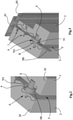
- the anchorage means 6 comprise a plurality of pawls 8, projecting from the at least one aforesaid shaped seat 100 of the first support frame 30 of the fixed wing 3 towards the second support frame 20 of the fixed framework 2 and a corresponding plurality of lever clips 9.
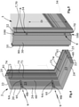
- the shaped seat 100 preferably has perimeter extension, as can be appreciated for example in figure 5 , so as to use the frame of a movable wing which has such shaped seat in order to contain the normal opening and closing hardware and possibly also the hinges. Otherwise, shaped seats 100 can also be provided, each for receiving a corresponding pawl 8.
- the head 9A is provided with a retention seat 95 for the pawl 8, provided with an opening 91 susceptible of being transversely crossed by the pawl 8.
- the retention seat 95 is defined by means of a curved rib 90 which projects towards the first support frame 30 of the fixed wing 3.
- the arm 9B is advantageously obtained in a single body with the head 9A and is manually actuatable to rotate around the head 9A between a retention position A of the fixed wing 3 ( figure 2 ), in which advantageously the arm 9B is aligned with the perimeter extension of the second support frame 20 of the fixed framework 2, and in which the curved rib 90 retains in the retention seat 95 the pawl 8, and a release position B of the fixed wing 3 ( figure 3 ), in which the arm 9B advantageously projects transversely to the plane of the second support frame 20 of the fixed framework 2, and in which the curved rib 90 releases the passage of the pawl 8 to exit from the retention seat 95 through the opening 91.
- the lever clips 9 can rotate with the arm 9B thereof within the slit F defined between the two frames 20 and 30 of the fixed framework 2 and of the fixed wing 3.
- the fixed wing 2 is inserted from the indoor setting into the space defined by the fixed framework 3 up to abutting against an abutment 60 directed towards the indoor setting.
- the openings 91 of the retention seats 95 of the lever clips 9 are substantially oriented towards the extension of the respective arms 9B.
- the openings 91 of at least two contiguous lever clips 9 are directed, when the latter are in retention position A, with orientation in opposite directions in order to avoid undesired clearances of the fixed wing 3 along a common direction of the openings 91.
- two arms 9B of the lever clips 9 are visible in a nearly final retention position and with the openings 91 as well as the relative arms 9B aligned with the openings 91, directed opposite.
- the fixed wing 3 is integrally and securely retained on the fixed framework 2 but simultaneously can be easily removed for example for maintenance operations, by simply manually rotating the arms 9B of the various lever clips 9.
- the lever clip 9 has substantially elongated plate form with the curved rib 90 that delimits the retention seat 95 provided at one end thereof.
- the lever clip 9 is pivoted to the sunken section 23A of the second support frame 20 of the fixed framework 2 by means of at least one second screw 92, which is advantageously provided on the head 9A of the lever clip 9, on the bottom of the retention seat 95 and at the center of the curved rib 90.
- first and the second screw 82, 92 are aligned with each other along the axis Y in figure 6 .
- the pawls 8 and the lever clips 9 of the corresponding pluralities are distributed along the sides of the perimeter of the first and of the second frame 20, 30 at a mutual distance D comprised between 25 and 55 cm and preferably of about 40 cm.
- the second perimeter gasket 71 is fixed to one of the two opposite perimeter faces 33, 23 of the first and of the second frame 30, 20, and is susceptible of acting against an opposite second flat section 33A of the perimeter face 33 of the opposite frame 20, 30, placed at an intermediate position between the internal opening F1 and the external opening F2 of the slit F.
- the first perimeter gasket 70 is arranged at the enlarged section F" of the slit F towards the internal opening F1 and is susceptible of concealing from view, from the interior, the lever clips 9 when the latter are rotated in retention position A.
- each pawl 8 is extended along an axis extended starting from a section having a non-circular geometric shape, i.e. provided with at least one larger axis D and with at least one smaller axis d, in particular obtained with an elliptical profile.
- the pawl 8 in this manner defines a narrow size directed towards the interior of the door or window and a widened size directed along the extension of the shaped seat 100.
- the pawl 8 enters into the retention seat 95 of the head 9A of the lever clip 9 in a facilitated manner by crossing the opening 91 thereof, due to its orientation which brings it to pass with its narrow size and then it is fittingly engaged with friction in the same retention seat 95 once the lever clip 9 has been rotated in the retention position A.
- the arm 9B of the lever clip for its actuation in rotation can have a tapered shape towards the free end as shown in figure 9 , and advantageously can also have an edge with at least one step 900 in order to be able to grip with a tool when the arm 9B is in retention position A within the slit F.
- the shaped seat 100 can be obtained by advantageously using that normally provided in a movable wing, in such case provided at its interior not with anchorage means but rather with hinging means as well as the hardware necessary for closing the fixed wing 3 on the fixed framework 2.
- Such shaped seat 100 of the second perimeter face 33 of the first frame 30 of the fixed wing 3 is arranged at the enlarged section F" of the slit F in order to make the arm 9B of the lever clips pass in a facilitated manner.
- the door or window 1 comprises a first protection framework 80, fixed to the first external surface 35 of the first frame 30 of the fixed wing 3 and a second protection framework 81 fixed to the second external surface 25 of the second frame 20 of the fixed framework 2.
- the seal means 7 comprising a fourth gasket 74 interposed between the first and the second protection framework 80, 81.
- the aforesaid fourth gasket 74 is advantageously mounted in a groove made on the second protection framework 81 at a section on top of the first protection framework 80 and it is directed towards the interior of the building.
Landscapes
- Engineering & Computer Science (AREA)
- Civil Engineering (AREA)
- Structural Engineering (AREA)
- Life Sciences & Earth Sciences (AREA)
- Wood Science & Technology (AREA)
- Wing Frames And Configurations (AREA)
Claims (12)
- Tür oder Fenster mit festem Flügel für den Außenbereich, die/das dazu bestimmt ist, in einer Öffnung eines Gebäudes montiert zu werden, um einen Innenbereich von einem Außenbereich zu trennen, Folgendes umfassend:- einen festen Flügel (3), der mit einem ersten Tragrahmen (30) und mit mindestens einer umlaufend an dem genannten Tragrahmen (30) befestigten Glasscheibe (40) ausgestattet ist;- einen festen Rahmen (2), der den genannten festen Flügel (3) trägt und mindestens einen zweiten Tragrahmen (20) umfasst;- Verankerungselemente (6), die den ersten Tragrahmen (30) des genannten festen Flügels (3) und den zweiten Tragrahmen (20) des genannten festen Rahmens (2) steif miteinander verbinden;wobei der erste Tragrahmen (30) des genannten festen Flügels (3) Folgendes aufweist:- eine erste umlaufende Fläche (32), die zum Inneren des genannten ersten Tragrahmens (30) gerichtet ist und die damit verbundene genannte Glasscheibe (40) mechanisch trägt;- eine zweite umlaufende Fläche (33), die zu dem genannten zweiten Tragrahmen (20) des festen Rahmens (2) gerichtet und mit mindestens einem Profil sitz (100) versehen ist;wobei der zweite Tragrahmen (20) des genannten festen Rahmens (2) Folgendes aufweist:- eine dritte umlaufende Fläche (22), die geeignet ist, an der tragenden Struktur eines Gebäudes an einer Öffnung befestigt zu werden,- eine vierte umlaufende Fläche (23), die zu dem genannten ersten Tragrahmen (30) des genannten festen Flügels (3) gerichtet und geeignet ist, an der zweiten umlaufenden Fläche (33) des ersten Tragrahmens (30) des genannten festen Flügels (3) mittels der genannten Verankerungselemente befestigt zu werden und einen dem Profilsitz (100) gegenüberliegenden vertieften Abschnitt (23A) aufweist, der in der zweiten umlaufenden Fläche (33) des ersten Tragrahmens (30) des genannten festen Flügels (3) eingerichtet ist;dadurch gekennzeichnet, dass die genannten Verankerungselemente (6) Folgendes umfassen:- eine Vielzahl von Sperrklinken (8), die von dem genannten mindestens einem Profil sitz (100) des ersten Tragrahmens (30) des genannten festen Flügels (3) zu dem zweiten Tragrahmen (20) des genannten festen Rahmens (2) vorstehen;- eine entsprechende Vielzahl von Hebelclips (9), von denen jeder Folgendes umfasst:- einen Kopf (9A), der zu dem vertieften Abschnitt (23A) des zweiten Tragrahmens (20) des genannten festen Rahmens (2) in eine der genannten Klinke (8) gegenüberliegende Position schwenkbar und mit einem Rückhaltesitz (95) für eine entsprechende Sperrklinke (8) ausgestattet ist und mit einer Öffnung (91) ausgestattet ist, die geeignet ist, von der genannten Sperrklinke (8) überquert zu werden;- einen Arm (9B), der von dem genannten Kopf (9A) vorsteht und von Hand betätigt werden kann, um den genannten Kopf (9A) zwischen einer Rückhalteposition (A) des genannten festen Flügels (3), in der der genannte Rückhaltesitz (95) die genannte Sperrklinke (8) zurückhält, und einer gelösten Position (B) des genannten festen Flügels (3), in der der genannte Rückhaltesitz (95) die Bewegung der genannten Klinke (8) durch die genannte Öffnung (91) freigibt, zu drehen.
- Tür oder Fenster mit festem Flügel für den Außenbereich nach Anspruch 1, dadurch gekennzeichnet, dass jeder genannte Hebelclip (9) den genannten Rückhaltesitz (95) mittels einer von dem ersten Tragrahmen (30) des genannten festen Flügels (3) vorstehenden gekrümmten Rippe (90) begrenzt, die von der genannten Öffnung (91) unterbrochen wird.
- Tür oder Fenster mit festem Flügel für den Außenbereich nach Anspruch 1 oder 2, dadurch gekennzeichnet, dass der genannte Arm (9B) mit dem Umfangsverlauf des genannten zweiten Tragrahmens (20) des genannten festen Rahmens (2) in der genannten Rückhalteposition (A) des genannten festen Flügels (3) ausgerichtet ist und quer von der Ebene des genannten zweiten Tragrahmens (20) des genannten festen Rahmens (2) in der genannten gelösten Position (B) des genannten festen Flügels (3) vorsteht.
- Tür oder Fenster mit festem Flügel für den Außenbereich nach einem beliebigen der vorangegangenen Ansprüche, dadurch gekennzeichnet, dass die genannte Sperrklinke (8) an der Unterseite des Profilsitzes (100) des ersten Tragrahmens (30) des genannten festen Flügels (3) mit Hilfe mindestens einer ersten Schraube (82) befestigt ist.
- Tür oder Fenster mit festem Flügel für den Außenbereich nach einem beliebigen der vorangegangenen Ansprüche, dadurch gekennzeichnet, dass der genannte Hebelclip (9) im Wesentlichen aus einer länglichen Platte mit der genannten gekrümmten Rippe (90) an einem Ende derselben besteht.
- Tür oder Fenster mit festem Flügel für den Außenbereich nach einem beliebigen der vorangegangenen Ansprüche, dadurch gekennzeichnet, dass der genannte Hebelclip (9) zu dem vertieften Abschnitt (23A) des zweiten Tragrahmens (20) des genannten festen Rahmens (2) mit Hilfe mindestens einer zweiten Schraube (92) schwenkbar ist.
- Tür oder Fenster mit festem Flügel für den Außenbereich nach Anspruch 6, dadurch gekennzeichnet, dass die genannte zweite Schraube (92) auf dem Kopf (9A) des genannten Hebelclips (9) in der Mitte der gekrümmten Rippe (90) und an der Unterseite des genannten Rückhaltesitzes (95) angeordnet ist.
- Tür oder Fenster mit festem Flügel für den Außenbereich nach einem beliebigen der vorangegangenen Ansprüche, dadurch gekennzeichnet, dass der genannte feste Flügel (3) an dem genannten festen Rahmen (2) anschlagend gegen einen zum Innenbereich gerichteten Anschlag (60) montiert ist und von dem genannten festen Rahmen (2) bei den genannten Hebelclips (9) in gelöster Position (B) des genannten festen Flügels (3) entnommen werden kann.
- Tür oder Fenster mit festem Flügel für den Außenbereich nach einem beliebigen der vorangegangenen Ansprüche, dadurch gekennzeichnet, dass die Sperrklinken (8) der genannten Vielzahl von Sperrklinken (8) und die Hebelclips (9) der genannten Vielzahl von Hebelclips (9) entlang der Seiten des Umfangs des genannten ersten und zweiten Rahmens (20, 30) in einem Abstand (D) zueinander zwischen 25 und 55 cm und vorzugsweise etwa 40 cm verteilt sind.
- Tür oder Fenster mit festem Flügel für den Außenbereich nach einem beliebigen der vorangegangenen Ansprüche, dadurch gekennzeichnet, dass die Öffnungen (91) der genannten Rückhaltesitze (95) gemäß der Verläufe der Arme (9B) der genannten Hebelclips (9) ausgerichtet sind.
- Tür oder Fenster mit festem Flügel für den Außenbereich nach einem beliebigen der vorangegangenen Ansprüche, dadurch gekennzeichnet, dass jeder Hebelclip (9) geeignet ist, mit seinem Arm (9B) in einem zwischen den beiden Tragrahmen (20, 30) des genannten festen Rahmens (2) und dem genannten festen Flügel (3) definierten Schlitz (F) zu drehen.
- Tür oder Fenster mit festem Flügel für den Außenbereich nach Anspruch 11, dadurch gekennzeichnet, dass eine erste Umfangsdichtung (70) zum Schließen des genannten Schlitzes (F) vorhanden und so untergebracht ist, dass die genannten Hebelclips (9) in der genannten Rückhalteposition (A) von der Innenseite her nicht erkennbar sind.
Applications Claiming Priority (1)
| Application Number | Priority Date | Filing Date | Title |
|---|---|---|---|
| IT201900014802 | 2019-08-14 |
Publications (2)
| Publication Number | Publication Date |
|---|---|
| EP3779113A1 EP3779113A1 (de) | 2021-02-17 |
| EP3779113B1 true EP3779113B1 (de) | 2022-02-23 |
Family
ID=69173192
Family Applications (1)
| Application Number | Title | Priority Date | Filing Date |
|---|---|---|---|
| EP20185725.7A Active EP3779113B1 (de) | 2019-08-14 | 2020-07-14 | Tür oder fenster mit festem flügel für den aussenbereich |
Country Status (1)
| Country | Link |
|---|---|
| EP (1) | EP3779113B1 (de) |
Family Cites Families (5)
| Publication number | Priority date | Publication date | Assignee | Title |
|---|---|---|---|---|
| CA677554A (en) * | 1964-01-07 | Gartner Karl | Device for fastening a panel or pane of glass | |
| US3296763A (en) * | 1964-07-28 | 1967-01-10 | Al Lipson | Devices for removably locking panels in framing |
| US4986046A (en) * | 1989-10-25 | 1991-01-22 | Mazzarantani Renato E | Method and apparatus for installing a curtain wall |
| DE29811003U1 (de) | 1998-06-19 | 1998-09-03 | Dimex Kunststofftechnik GmbH, 72147 Nehren | Einrichtung zur Befestigung eines Blendrahmens |
| SE0100233L (sv) | 2001-01-26 | 2002-09-03 | Bombardier Transp Gmbh | Ett fixerat fönster och ett sätt att fixera ett fönster |
-
2020
- 2020-07-14 EP EP20185725.7A patent/EP3779113B1/de active Active
Also Published As
| Publication number | Publication date |
|---|---|
| EP3779113A1 (de) | 2021-02-17 |
Similar Documents
| Publication | Publication Date | Title |
|---|---|---|
| AU2023201654B2 (en) | Window frame and architrave assembly | |
| EP2567040B1 (de) | Montagehalterung für eine strukturell verglaste feuerschutzscheibe | |
| US20080168724A1 (en) | Curtain-wall assembly | |
| WO2015051545A1 (zh) | 一种建筑用幕墙 | |
| EA039728B1 (ru) | Светопрозрачный фасад модульного типа и способ замены заполняющего элемента в светопрозрачном фасаде | |
| RU2599243C1 (ru) | Система строительных светопрозрачных ограждающих конструкций | |
| EP3779113A1 (de) | Tür/fenster mit festem flügel für den aussenbereich | |
| US8915032B1 (en) | Frameless impact window system | |
| US20110107692A1 (en) | Storm shutter assembly | |
| EP3748116B1 (de) | Tür oder fenster | |
| EP3587721B1 (de) | Fenster, tür oder klappe für aussenbereiche, verfahren zur montage davon und verriegelungsanordnung zum verriegeln eines paneels mit einem lasttragenden rahmen von besagter fenster, tür oder klappe | |
| IT201900002820U1 (it) | Serramento ad anta fissa | |
| US20240247535A1 (en) | Attachable blind bracket for window | |
| US7712269B2 (en) | Fastener device | |
| DK172375B1 (da) | Modulsystem for bygningsfacader | |
| AU2023201377B2 (en) | A wall assembly | |
| US20100236168A1 (en) | High Impact Storm Panel | |
| CN222667042U (zh) | 一种可开启的封闭阳台结构、系统及建筑 | |
| US20250223870A1 (en) | Modular gate assembly and method of constructing a gate assembly | |
| CN212201751U (zh) | 一种窗纱一体化内平开窗 | |
| JP7213715B2 (ja) | 壁面構成体 | |
| EP0474582A1 (de) | Balkonabdeckungssystem für in der Renovierung befindlichen mehrstöckigen Gebäuden | |
| EP1682742A1 (de) | Fenster- oder türkonstruktion mit einem einen stützhalter aufweisenden beschlag | |
| JPH0328143Y2 (de) | ||
| JPS5838869Y2 (ja) | 面格子付き窓枠 |
Legal Events
| Date | Code | Title | Description |
|---|---|---|---|
| PUAI | Public reference made under article 153(3) epc to a published international application that has entered the european phase |
Free format text: ORIGINAL CODE: 0009012 |
|
| STAA | Information on the status of an ep patent application or granted ep patent |
Free format text: STATUS: THE APPLICATION HAS BEEN PUBLISHED |
|
| AK | Designated contracting states |
Kind code of ref document: A1 Designated state(s): AL AT BE BG CH CY CZ DE DK EE ES FI FR GB GR HR HU IE IS IT LI LT LU LV MC MK MT NL NO PL PT RO RS SE SI SK SM TR |
|
| AX | Request for extension of the european patent |
Extension state: BA ME |
|
| STAA | Information on the status of an ep patent application or granted ep patent |
Free format text: STATUS: REQUEST FOR EXAMINATION WAS MADE |
|
| 17P | Request for examination filed |
Effective date: 20210714 |
|
| RBV | Designated contracting states (corrected) |
Designated state(s): AL AT BE BG CH CY CZ DE DK EE ES FI FR GB GR HR HU IE IS IT LI LT LU LV MC MK MT NL NO PL PT RO RS SE SI SK SM TR |
|
| GRAP | Despatch of communication of intention to grant a patent |
Free format text: ORIGINAL CODE: EPIDOSNIGR1 |
|
| STAA | Information on the status of an ep patent application or granted ep patent |
Free format text: STATUS: GRANT OF PATENT IS INTENDED |
|
| INTG | Intention to grant announced |
Effective date: 20210903 |
|
| GRAS | Grant fee paid |
Free format text: ORIGINAL CODE: EPIDOSNIGR3 |
|
| GRAA | (expected) grant |
Free format text: ORIGINAL CODE: 0009210 |
|
| STAA | Information on the status of an ep patent application or granted ep patent |
Free format text: STATUS: THE PATENT HAS BEEN GRANTED |
|
| AK | Designated contracting states |
Kind code of ref document: B1 Designated state(s): AL AT BE BG CH CY CZ DE DK EE ES FI FR GB GR HR HU IE IS IT LI LT LU LV MC MK MT NL NO PL PT RO RS SE SI SK SM TR |
|
| REG | Reference to a national code |
Ref country code: GB Ref legal event code: FG4D |
|
| REG | Reference to a national code |
Ref country code: CH Ref legal event code: EP |
|
| REG | Reference to a national code |
Ref country code: DE Ref legal event code: R096 Ref document number: 602020001949 Country of ref document: DE |
|
| REG | Reference to a national code |
Ref country code: AT Ref legal event code: REF Ref document number: 1470596 Country of ref document: AT Kind code of ref document: T Effective date: 20220315 |
|
| REG | Reference to a national code |
Ref country code: IE Ref legal event code: FG4D |
|
| REG | Reference to a national code |
Ref country code: LT Ref legal event code: MG9D |
|
| REG | Reference to a national code |
Ref country code: NL Ref legal event code: MP Effective date: 20220223 |
|
| REG | Reference to a national code |
Ref country code: AT Ref legal event code: MK05 Ref document number: 1470596 Country of ref document: AT Kind code of ref document: T Effective date: 20220223 |
|
| PG25 | Lapsed in a contracting state [announced via postgrant information from national office to epo] |
Ref country code: SE Free format text: LAPSE BECAUSE OF FAILURE TO SUBMIT A TRANSLATION OF THE DESCRIPTION OR TO PAY THE FEE WITHIN THE PRESCRIBED TIME-LIMIT Effective date: 20220223 Ref country code: RS Free format text: LAPSE BECAUSE OF FAILURE TO SUBMIT A TRANSLATION OF THE DESCRIPTION OR TO PAY THE FEE WITHIN THE PRESCRIBED TIME-LIMIT Effective date: 20220223 Ref country code: PT Free format text: LAPSE BECAUSE OF FAILURE TO SUBMIT A TRANSLATION OF THE DESCRIPTION OR TO PAY THE FEE WITHIN THE PRESCRIBED TIME-LIMIT Effective date: 20220623 Ref country code: NO Free format text: LAPSE BECAUSE OF FAILURE TO SUBMIT A TRANSLATION OF THE DESCRIPTION OR TO PAY THE FEE WITHIN THE PRESCRIBED TIME-LIMIT Effective date: 20220523 Ref country code: NL Free format text: LAPSE BECAUSE OF FAILURE TO SUBMIT A TRANSLATION OF THE DESCRIPTION OR TO PAY THE FEE WITHIN THE PRESCRIBED TIME-LIMIT Effective date: 20220223 Ref country code: LT Free format text: LAPSE BECAUSE OF FAILURE TO SUBMIT A TRANSLATION OF THE DESCRIPTION OR TO PAY THE FEE WITHIN THE PRESCRIBED TIME-LIMIT Effective date: 20220223 Ref country code: HR Free format text: LAPSE BECAUSE OF FAILURE TO SUBMIT A TRANSLATION OF THE DESCRIPTION OR TO PAY THE FEE WITHIN THE PRESCRIBED TIME-LIMIT Effective date: 20220223 Ref country code: ES Free format text: LAPSE BECAUSE OF FAILURE TO SUBMIT A TRANSLATION OF THE DESCRIPTION OR TO PAY THE FEE WITHIN THE PRESCRIBED TIME-LIMIT Effective date: 20220223 Ref country code: BG Free format text: LAPSE BECAUSE OF FAILURE TO SUBMIT A TRANSLATION OF THE DESCRIPTION OR TO PAY THE FEE WITHIN THE PRESCRIBED TIME-LIMIT Effective date: 20220523 |
|
| PG25 | Lapsed in a contracting state [announced via postgrant information from national office to epo] |
Ref country code: PL Free format text: LAPSE BECAUSE OF FAILURE TO SUBMIT A TRANSLATION OF THE DESCRIPTION OR TO PAY THE FEE WITHIN THE PRESCRIBED TIME-LIMIT Effective date: 20220223 Ref country code: LV Free format text: LAPSE BECAUSE OF FAILURE TO SUBMIT A TRANSLATION OF THE DESCRIPTION OR TO PAY THE FEE WITHIN THE PRESCRIBED TIME-LIMIT Effective date: 20220223 Ref country code: GR Free format text: LAPSE BECAUSE OF FAILURE TO SUBMIT A TRANSLATION OF THE DESCRIPTION OR TO PAY THE FEE WITHIN THE PRESCRIBED TIME-LIMIT Effective date: 20220524 Ref country code: FI Free format text: LAPSE BECAUSE OF FAILURE TO SUBMIT A TRANSLATION OF THE DESCRIPTION OR TO PAY THE FEE WITHIN THE PRESCRIBED TIME-LIMIT Effective date: 20220223 Ref country code: AT Free format text: LAPSE BECAUSE OF FAILURE TO SUBMIT A TRANSLATION OF THE DESCRIPTION OR TO PAY THE FEE WITHIN THE PRESCRIBED TIME-LIMIT Effective date: 20220223 |
|
| PG25 | Lapsed in a contracting state [announced via postgrant information from national office to epo] |
Ref country code: IS Free format text: LAPSE BECAUSE OF FAILURE TO SUBMIT A TRANSLATION OF THE DESCRIPTION OR TO PAY THE FEE WITHIN THE PRESCRIBED TIME-LIMIT Effective date: 20220623 |
|
| PG25 | Lapsed in a contracting state [announced via postgrant information from national office to epo] |
Ref country code: SM Free format text: LAPSE BECAUSE OF FAILURE TO SUBMIT A TRANSLATION OF THE DESCRIPTION OR TO PAY THE FEE WITHIN THE PRESCRIBED TIME-LIMIT Effective date: 20220223 Ref country code: SK Free format text: LAPSE BECAUSE OF FAILURE TO SUBMIT A TRANSLATION OF THE DESCRIPTION OR TO PAY THE FEE WITHIN THE PRESCRIBED TIME-LIMIT Effective date: 20220223 Ref country code: RO Free format text: LAPSE BECAUSE OF FAILURE TO SUBMIT A TRANSLATION OF THE DESCRIPTION OR TO PAY THE FEE WITHIN THE PRESCRIBED TIME-LIMIT Effective date: 20220223 Ref country code: EE Free format text: LAPSE BECAUSE OF FAILURE TO SUBMIT A TRANSLATION OF THE DESCRIPTION OR TO PAY THE FEE WITHIN THE PRESCRIBED TIME-LIMIT Effective date: 20220223 Ref country code: DK Free format text: LAPSE BECAUSE OF FAILURE TO SUBMIT A TRANSLATION OF THE DESCRIPTION OR TO PAY THE FEE WITHIN THE PRESCRIBED TIME-LIMIT Effective date: 20220223 Ref country code: CZ Free format text: LAPSE BECAUSE OF FAILURE TO SUBMIT A TRANSLATION OF THE DESCRIPTION OR TO PAY THE FEE WITHIN THE PRESCRIBED TIME-LIMIT Effective date: 20220223 |
|
| PGFP | Annual fee paid to national office [announced via postgrant information from national office to epo] |
Ref country code: DE Payment date: 20220720 Year of fee payment: 3 |
|
| REG | Reference to a national code |
Ref country code: DE Ref legal event code: R097 Ref document number: 602020001949 Country of ref document: DE |
|
| PG25 | Lapsed in a contracting state [announced via postgrant information from national office to epo] |
Ref country code: AL Free format text: LAPSE BECAUSE OF FAILURE TO SUBMIT A TRANSLATION OF THE DESCRIPTION OR TO PAY THE FEE WITHIN THE PRESCRIBED TIME-LIMIT Effective date: 20220223 |
|
| PGFP | Annual fee paid to national office [announced via postgrant information from national office to epo] |
Ref country code: FR Payment date: 20220720 Year of fee payment: 3 |
|
| PLBE | No opposition filed within time limit |
Free format text: ORIGINAL CODE: 0009261 |
|
| STAA | Information on the status of an ep patent application or granted ep patent |
Free format text: STATUS: NO OPPOSITION FILED WITHIN TIME LIMIT |
|
| 26N | No opposition filed |
Effective date: 20221124 |
|
| PG25 | Lapsed in a contracting state [announced via postgrant information from national office to epo] |
Ref country code: SI Free format text: LAPSE BECAUSE OF FAILURE TO SUBMIT A TRANSLATION OF THE DESCRIPTION OR TO PAY THE FEE WITHIN THE PRESCRIBED TIME-LIMIT Effective date: 20220223 Ref country code: MC Free format text: LAPSE BECAUSE OF FAILURE TO SUBMIT A TRANSLATION OF THE DESCRIPTION OR TO PAY THE FEE WITHIN THE PRESCRIBED TIME-LIMIT Effective date: 20220223 |
|
| REG | Reference to a national code |
Ref country code: BE Ref legal event code: MM Effective date: 20220731 |
|
| PG25 | Lapsed in a contracting state [announced via postgrant information from national office to epo] |
Ref country code: LU Free format text: LAPSE BECAUSE OF NON-PAYMENT OF DUE FEES Effective date: 20220714 |
|
| PG25 | Lapsed in a contracting state [announced via postgrant information from national office to epo] |
Ref country code: BE Free format text: LAPSE BECAUSE OF NON-PAYMENT OF DUE FEES Effective date: 20220731 |
|
| P01 | Opt-out of the competence of the unified patent court (upc) registered |
Effective date: 20230302 |
|
| PG25 | Lapsed in a contracting state [announced via postgrant information from national office to epo] |
Ref country code: IE Free format text: LAPSE BECAUSE OF NON-PAYMENT OF DUE FEES Effective date: 20220714 |
|
| REG | Reference to a national code |
Ref country code: DE Ref legal event code: R119 Ref document number: 602020001949 Country of ref document: DE |
|
| REG | Reference to a national code |
Ref country code: CH Ref legal event code: PL |
|
| PG25 | Lapsed in a contracting state [announced via postgrant information from national office to epo] |
Ref country code: MK Free format text: LAPSE BECAUSE OF FAILURE TO SUBMIT A TRANSLATION OF THE DESCRIPTION OR TO PAY THE FEE WITHIN THE PRESCRIBED TIME-LIMIT Effective date: 20220223 Ref country code: DE Free format text: LAPSE BECAUSE OF NON-PAYMENT OF DUE FEES Effective date: 20240201 Ref country code: CY Free format text: LAPSE BECAUSE OF FAILURE TO SUBMIT A TRANSLATION OF THE DESCRIPTION OR TO PAY THE FEE WITHIN THE PRESCRIBED TIME-LIMIT Effective date: 20220223 Ref country code: CH Free format text: LAPSE BECAUSE OF NON-PAYMENT OF DUE FEES Effective date: 20230731 |
|
| PG25 | Lapsed in a contracting state [announced via postgrant information from national office to epo] |
Ref country code: HU Free format text: LAPSE BECAUSE OF FAILURE TO SUBMIT A TRANSLATION OF THE DESCRIPTION OR TO PAY THE FEE WITHIN THE PRESCRIBED TIME-LIMIT; INVALID AB INITIO Effective date: 20200714 Ref country code: FR Free format text: LAPSE BECAUSE OF NON-PAYMENT OF DUE FEES Effective date: 20230731 |
|
| PG25 | Lapsed in a contracting state [announced via postgrant information from national office to epo] |
Ref country code: MT Free format text: LAPSE BECAUSE OF FAILURE TO SUBMIT A TRANSLATION OF THE DESCRIPTION OR TO PAY THE FEE WITHIN THE PRESCRIBED TIME-LIMIT Effective date: 20220223 |
|
| GBPC | Gb: european patent ceased through non-payment of renewal fee |
Effective date: 20240714 |
|
| PG25 | Lapsed in a contracting state [announced via postgrant information from national office to epo] |
Ref country code: GB Free format text: LAPSE BECAUSE OF NON-PAYMENT OF DUE FEES Effective date: 20240714 |
|
| PGFP | Annual fee paid to national office [announced via postgrant information from national office to epo] |
Ref country code: IT Payment date: 20250724 Year of fee payment: 6 |
|
| PG25 | Lapsed in a contracting state [announced via postgrant information from national office to epo] |
Ref country code: TR Free format text: LAPSE BECAUSE OF FAILURE TO SUBMIT A TRANSLATION OF THE DESCRIPTION OR TO PAY THE FEE WITHIN THE PRESCRIBED TIME-LIMIT Effective date: 20220223 |
|
| PG25 | Lapsed in a contracting state [announced via postgrant information from national office to epo] |
Ref country code: CH Free format text: THE PATENT HAS BEEN ANNULLED BY A DECISION OF A NATIONAL AUTHORITY Effective date: 20230731 |