EP3779145A1 - Dispositif de compression variable et système de moteur - Google Patents
Dispositif de compression variable et système de moteur Download PDFInfo
- Publication number
- EP3779145A1 EP3779145A1 EP19782445.1A EP19782445A EP3779145A1 EP 3779145 A1 EP3779145 A1 EP 3779145A1 EP 19782445 A EP19782445 A EP 19782445A EP 3779145 A1 EP3779145 A1 EP 3779145A1
- Authority
- EP
- European Patent Office
- Prior art keywords
- piston rod
- compression device
- fluid chamber
- regulation
- variable compression
- Prior art date
- Legal status (The legal status is an assumption and is not a legal conclusion. Google has not performed a legal analysis and makes no representation as to the accuracy of the status listed.)
- Granted
Links
Images


Classifications
-
- F—MECHANICAL ENGINEERING; LIGHTING; HEATING; WEAPONS; BLASTING
- F02—COMBUSTION ENGINES; HOT-GAS OR COMBUSTION-PRODUCT ENGINE PLANTS
- F02B—INTERNAL-COMBUSTION PISTON ENGINES; COMBUSTION ENGINES IN GENERAL
- F02B75/00—Other engines
- F02B75/04—Engines with variable distances between pistons at top dead-centre positions and cylinder heads
- F02B75/044—Engines with variable distances between pistons at top dead-centre positions and cylinder heads by means of an adjustable piston length
-
- F—MECHANICAL ENGINEERING; LIGHTING; HEATING; WEAPONS; BLASTING
- F02—COMBUSTION ENGINES; HOT-GAS OR COMBUSTION-PRODUCT ENGINE PLANTS
- F02B—INTERNAL-COMBUSTION PISTON ENGINES; COMBUSTION ENGINES IN GENERAL
- F02B75/00—Other engines
- F02B75/04—Engines with variable distances between pistons at top dead-centre positions and cylinder heads
-
- F—MECHANICAL ENGINEERING; LIGHTING; HEATING; WEAPONS; BLASTING
- F01—MACHINES OR ENGINES IN GENERAL; ENGINE PLANTS IN GENERAL; STEAM ENGINES
- F01B—MACHINES OR ENGINES, IN GENERAL OR OF POSITIVE-DISPLACEMENT TYPE, e.g. STEAM ENGINES
- F01B31/00—Component parts, details or accessories not provided for in, or of interest apart from, other groups
- F01B31/14—Changing of compression ratio
-
- F—MECHANICAL ENGINEERING; LIGHTING; HEATING; WEAPONS; BLASTING
- F02—COMBUSTION ENGINES; HOT-GAS OR COMBUSTION-PRODUCT ENGINE PLANTS
- F02B—INTERNAL-COMBUSTION PISTON ENGINES; COMBUSTION ENGINES IN GENERAL
- F02B75/00—Other engines
- F02B75/32—Engines characterised by connections between pistons and main shafts and not specific to preceding main groups
-
- F—MECHANICAL ENGINEERING; LIGHTING; HEATING; WEAPONS; BLASTING
- F02—COMBUSTION ENGINES; HOT-GAS OR COMBUSTION-PRODUCT ENGINE PLANTS
- F02D—CONTROLLING COMBUSTION ENGINES
- F02D15/00—Varying compression ratio
- F02D15/02—Varying compression ratio by alteration or displacement of piston stroke
-
- F—MECHANICAL ENGINEERING; LIGHTING; HEATING; WEAPONS; BLASTING
- F02—COMBUSTION ENGINES; HOT-GAS OR COMBUSTION-PRODUCT ENGINE PLANTS
- F02B—INTERNAL-COMBUSTION PISTON ENGINES; COMBUSTION ENGINES IN GENERAL
- F02B75/00—Other engines
- F02B75/04—Engines with variable distances between pistons at top dead-centre positions and cylinder heads
- F02B75/045—Engines with variable distances between pistons at top dead-centre positions and cylinder heads by means of a variable connecting rod length
-
- F—MECHANICAL ENGINEERING; LIGHTING; HEATING; WEAPONS; BLASTING
- F02—COMBUSTION ENGINES; HOT-GAS OR COMBUSTION-PRODUCT ENGINE PLANTS
- F02D—CONTROLLING COMBUSTION ENGINES
- F02D15/00—Varying compression ratio
- F02D15/04—Varying compression ratio by alteration of volume of compression space without changing piston stroke
-
- F—MECHANICAL ENGINEERING; LIGHTING; HEATING; WEAPONS; BLASTING
- F02—COMBUSTION ENGINES; HOT-GAS OR COMBUSTION-PRODUCT ENGINE PLANTS
- F02D—CONTROLLING COMBUSTION ENGINES
- F02D41/00—Electrical control of supply of combustible mixture or its constituents
- F02D41/0002—Controlling intake air
- F02D2041/001—Controlling intake air for engines with variable valve actuation
-
- F—MECHANICAL ENGINEERING; LIGHTING; HEATING; WEAPONS; BLASTING
- F02—COMBUSTION ENGINES; HOT-GAS OR COMBUSTION-PRODUCT ENGINE PLANTS
- F02D—CONTROLLING COMBUSTION ENGINES
- F02D2700/00—Mechanical control of speed or power of a single cylinder piston engine
- F02D2700/03—Controlling by changing the compression ratio
-
- Y—GENERAL TAGGING OF NEW TECHNOLOGICAL DEVELOPMENTS; GENERAL TAGGING OF CROSS-SECTIONAL TECHNOLOGIES SPANNING OVER SEVERAL SECTIONS OF THE IPC; TECHNICAL SUBJECTS COVERED BY FORMER USPC CROSS-REFERENCE ART COLLECTIONS [XRACs] AND DIGESTS
- Y02—TECHNOLOGIES OR APPLICATIONS FOR MITIGATION OR ADAPTATION AGAINST CLIMATE CHANGE
- Y02T—CLIMATE CHANGE MITIGATION TECHNOLOGIES RELATED TO TRANSPORTATION
- Y02T10/00—Road transport of goods or passengers
- Y02T10/10—Internal combustion engine [ICE] based vehicles
- Y02T10/30—Use of alternative fuels, e.g. biofuels
Definitions
- the present disclosure relates to a variable compression device and an engine system.
- Patent Document 1 discloses a large reciprocating piston combustion engine including a crosshead.
- the large reciprocating piston combustion engine disclosed in Patent Document 1 is a dual fuel engine that can be operated using both a liquid fuel such as heavy oil and a gaseous fuel such as natural gas.
- an adjustment mechanism (variable compression device) that changes a compression ratio by moving a piston rod using hydraulic pressure is provided in a crosshead portion.
- Patent Document 1 Japanese Unexamined Patent Application, First Publication No. 2014-20375
- a variable compression device having such a configuration includes a regulation member that regulates movement of a piston rod in a direction in which a compression ratio is increased.
- a downward force for pushing down a piston due to pressure inside a cylinder becomes smaller than an upward inertial force caused by the reciprocation of the piston rod, and thus the piston rod rises due to its own inertial force regardless of an oil pressure of a lower oil chamber.
- the regulation member and the piston rod collide with each other.
- the piston rod abuts the regulation member.
- the piston rod when the piston rod is moved in a state where combustion pressure is not generated inside a combustion chamber such as a case where an engine is started, the piston rod may collide with the regulation member, which leads to a possibility that a large force may be applied to the regulation member.
- the disclosure has been made in view of the above-described problems, and an object thereof is to prevent a regulation member and a piston rod from colliding with each other in a variable compression device.
- the disclosure has been made in view of the above-described problems, and an object thereof is to minimize collision energy which is applied to a regulation member from a piston rod.
- a variable compression device is configured to change a compression ratio in a combustion chamber of an engine and includes a piston rod, a first fluid chamber which is configured to move the piston rod in a direction in which a compression ratio is increased by supplying a pressurized working fluid thereto, a regulation member which is configured to regulate movement of the piston rod in a direction in which a compression ratio is increased, a second fluid chamber which is provided between the piston rod and the regulation member and is configured to store the working fluid, a supply flow path which is configured to guide the working fluid supplied to the second fluid chamber, a discharge flow path which is configured to guide the working fluid discharged from the second fluid chamber, and a flow rate regulation unit which is provided in the discharge flow path and is configured to regulate a flow of the working fluid when the piston rod approaches the regulation member.
- the flow rate regulation unit may include a weight member which is movable together with the piston rod, and a valve which is moved in a valve closing direction by movement of the weight member.
- the flow rate regulation unit may include a biasing member that is configured to bias the weight member in a valve opening direction.
- variable compression device a portion of the working fluid supplied to the first fluid chamber may be supplied to the second fluid chamber.
- variable compression device may further include a fluid chamber forming member which forms a portion of the first fluid chamber, and an absorption member which is fixed to the regulation member or the piston rod, and is configured to absorb collision energy between the regulation member and the piston rod by elastic deformation.
- variable compression device may further include a fixing member which is configured to fix the regulation member to the fluid chamber forming member
- the fixing member may include a shaft portion which is inserted into the regulation member and the fluid chamber forming member, and a head portion which is fixed to the shaft portion and is disposed separately from the regulation member, and the absorption member may be provided between the regulation member and the head portion.
- the absorption member may be provided between the regulation member and the piston rod.
- the regulation member may include a concave portion to which the absorption member is fitted.
- An engine system includes the variable compression device.
- a flow rate regulation unit closes a discharge flow path, and thus it is possible to maintain a state where hydraulic oil is stored in a second fluid chamber.
- a working fluid in the second fluid chamber operates as a damper, so that it is possible to prevent the piston rod from colliding with the regulation member with a large force.
- an absorption member is elastically deformed, so that it is possible to absorb collision energy generated when the piston rod collides with the regulation member. Therefore, it is possible to reduce collision energy received by the regulation member from the piston rod and to reduce an impact to be applied to the regulation member.
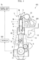
- An engine system 100 of the present embodiment is mounted in a ship such as a large tanker. As shown in Fig. 1 , the engine system 100 includes an engine 1, a supercharger 200, and a controller 300. Meanwhile, in the present embodiment, description will be given by regarding the supercharger 200 as an auxiliary device and providing the supercharger 200 as a separate body from the engine 1 (main device). However, the supercharger 200 may be configured as a part of the engine 1.
- the engine 1 is a multi-cylinder uniflow scavenging diesel engine.
- the engine 1 has a gas operation mode in which a gaseous fuel such as natural gas is burned together with a liquid fuel such as heavy oil, and a diesel operation mode in which a liquid fuel such as heavy oil is burned. Meanwhile, in the gas operation mode, only a gaseous fuel may be burned.
- the engine 1 includes a frame 2, a cylinder portion 3, a piston 4, an exhaust valve unit 5, a piston rod 6, a crosshead 7, a hydraulic portion 8 (boosting mechanism), a connecting rod 9, a crank angle sensor 10, a crank shaft 11, a scavenging reservoir 12, an exhaust reservoir 13, an air cooler 14, and an upper hydraulic chamber hydraulic mechanism 15.
- a cylinder is constituted by the cylinder portion 3, the piston 4, the exhaust valve unit 5, and the piston rod 6.
- the frame 2 is a strength member that supports the entire engine 1, and accommodates the crosshead 7, the hydraulic portion 8, and the connecting rod 9 therein.
- a crosshead pin 7a to be described later of the crosshead 7 can be reciprocated inside the frame 2.
- the cylinder portion 3 includes a cylindrical cylinder liner 3a, a cylinder head 3b, and a cylinder jacket 3c.
- the cylinder liner 3a is a cylindrical member.
- a sliding surface with respect to the piston 4 is formed on the inner side (inner circumferential surface) of the cylinder liner 3a.
- a space surrounded by the inner circumferential surface of the cylinder liner 3a and the piston 4 serves as a combustion chamber R1.
- a plurality of scavenging ports S are formed in a lower portion of the cylinder liner 3a.
- the scavenging ports S are openings which are arranged along the circumferential surface of the cylinder liner 3a and make a scavenging chamber R2 inside the cylinder jacket 3c and the inner side of the cylinder liner 3a communicate with each other.
- the cylinder head 3b is a lid member provided in an upper end portion of the cylinder liner 3a.
- An exhaust port H is formed in the central portion of the cylinder head 3b when seen in a plan view. The exhaust port H is connected to the exhaust reservoir 13.
- a fuel injection valve (not shown) is provided in the cylinder head 3b.
- a cylinder internal pressure sensor (not shown) is provided in the vicinity of the fuel injection valve of the cylinder head 3b.
- the cylinder internal pressure sensor detects a pressure in the combustion chamber R1 and transmits the detected pressure to the controller 300.
- the cylinder jacket 3c is a cylindrical or box-shaped member which is provided between the frame 2 and the cylinder liner 3a and into which a lower end portion of the cylinder liner 3a is inserted.
- the scavenging chamber R2 is formed inside the cylinder jacket 3c.
- the scavenging chamber R2 of the cylinder jacket 3c is connected to the scavenging reservoir 12.
- the piston 4 having a substantially columnar shape is connected to the piston rod 6 to be described later and is disposed on the inner side of the cylinder liner 3a.
- a piston ring (not shown) is provided on the outer circumferential surface of the piston 4, and a gap between the piston 4 and the cylinder liner 3a is sealed by the piston ring.
- the piston 4 slides inside the cylinder liner 3a together with the piston rod 6 due to a fluctuation in pressure in the combustion chamber R1.
- the exhaust valve unit 5 includes an exhaust valve 5a, an exhaust valve casing 5b, and an exhaust valve driving unit (not shown).
- the exhaust valve 5a is provided on the inner side of the cylinder head 3b and closes the exhaust port H in the cylinder portion 3 by the exhaust valve driving unit.
- the exhaust valve casing 5b is a cylindrical housing that accommodates an end portion of the exhaust valve 5a.
- the exhaust valve driving unit is an actuator that moves the exhaust valve 5a in a direction parallel to a stroke direction of the piston 4.
- the piston rod 6 is an elongate member having one end connected to the piston 4 and the other end coupled to the crosshead pin 7a. An end portion of the piston rod 6 is inserted into the crosshead pin 7a, and the connecting rod 9 is rotatably coupled to the crosshead pin 7a. A portion of the end portion of the piston rod 6 on the crosshead pin 7a side has a large diameter portion formed to have a large diameter.
- the crosshead 7 includes the crosshead pin 7a, a guide shoe 7b, and a lid member 7c (regulation member).
- the crosshead pin 7a is a columnar shape member that movably couples the piston rod 6 and the connecting rod 9 to each other.
- a hydraulic chamber R3 (fluid chamber, first fluid chamber) to and from which hydraulic oil (working fluid) is supplied and discharged is formed in an insertion space of the crosshead pin 7a where the end portion of the piston rod 6 is inserted.
- An outlet hole O penetrating the crosshead pin 7a in the axial direction of the crosshead pin 7a is formed on a side lower than the center of the crosshead pin 7a.
- the outlet hole O is an opening through which cooling oil having passed through a cooling flow passage (not shown) of the piston rod 6 is discharged.
- the crosshead pin 7a is provided with a supply flow passage R4 that connects the hydraulic chamber R3 and a plunger pump 8c to be described later to each other, and a relief flow passage R5 that connects the hydraulic chamber R3 and a relief valve 8f to be described later to each other.
- the guide shoe 7b rotatably supports the crosshead pin 7a.
- the guide shoe 7b moves, on a guide rail (not shown), in the stroke direction of the piston 4 in association with the crosshead pin 7a.
- the guide shoe 7b moves along the guide rail, so that the crosshead pin 7a is regulated with respect to a rotational motion and to movement other than movement in a linear direction parallel to the stroke direction of the piston 4.
- the lid member 7c is an annular member which is fixed to an upper portion of the crosshead pin 7a and into which the end portion of the piston rod 6 is inserted.
- a seal ring is provided on a sliding surface of the lid member 7c with respect to the piston rod 6.
- an upper hydraulic chamber R6 (regulation member-side fluid chamber, second fluid chamber) is formed between the lid member 7c and the large diameter portion of the piston rod 6.
- a portion of a supply flow path R7 for guiding hydraulic oil supplied to the upper hydraulic chamber R6 and a portion of a discharge flow path R8 for guiding hydraulic oil discharged from the upper hydraulic chamber R6 are formed in the lid member 7c.
- the crosshead 7 transmits a linear motion of the piston 4 to the connecting rod 9.
- the hydraulic portion 8 includes a supply pump 8a, an oscillating pipe 8b, the plunger pump 8c, a first check valve 8d and a second check valve 8e included in the plunger pump 8c, and the relief valve 8f.
- the piston rod 6, the crosshead 7, the hydraulic portion 8, the upper hydraulic chamber hydraulic mechanism 15, and the controller 300 function as a variable compression device in the present embodiment.
- the supply pump 8a pressurizes hydraulic oil supplied from a hydraulic oil tank (not shown) and supplies the pressurized hydraulic oil to the plunger pump 8c on the basis of an instruction received from the controller 300.
- the supply pump 8a is driven using power of a generator of the ship and can be operated before a liquid fuel is supplied to the combustion chamber R1.
- the oscillating pipe 8b connects the supply pump 8a and the plunger pump 8c of each cylinder to each other.
- the oscillating pipe 8b is slidable between the plunger pump 8c moving in association with the crosshead pin 7a and the fixed supply pump 8a.
- the plunger pump 8c is fixed to the crosshead pin 7a.
- the plunger pump 8c includes a rod-shaped plunger 8c1, a tubular cylinder 8c2 that slidably accommodates the plunger 8c1, and a plunger driving unit 8c3.
- the plunger 8c1 slides inside the cylinder 8c2 by a driving unit (not shown) connected to the plunger 8c1, thereby pressurizing hydraulic oil and supplying the pressurized hydraulic oil to the hydraulic chamber R3.
- first check valve 8d is provided in an opening, on an ejection side of hydraulic oil, which is provided in an end portion of the cylinder 8c2
- second check valve 8e is provided in an opening, on an injection side of hydraulic oil, which is provided on the side circumferential surface of the cylinder 8c2.
- the plunger driving unit 8c3 is connected to the plunger 8c1 and reciprocates the plunger 8c1 on the basis of an instruction received from the controller 300.
- the first check valve 8d is configured to be closed by a valve body being biased toward the inner side of the cylinder 8c2 and prevents hydraulic oil supplied to the hydraulic chamber R3 from flowing backward to the cylinder 8c2.
- the first check valve 8d is opened by the valve body being pressed by hydraulic oil when the pressure of the hydraulic oil in the cylinder 8c2 becomes equal to or higher than a biasing force (valve-opening pressure) of a biasing member of the first check valve 8d.
- the second check valve 8e is biased toward the outer side of the cylinder 8c2 and prevents the hydraulic oil supplied to the cylinder 8c2 from flowing backward to the supply pump 8a.
- the second check valve 8e is opened by the valve body being pressed by hydraulic oil when the pressure of the hydraulic oil supplied from the supply pump 8a becomes equal to or higher than a biasing force (valve-opening pressure) of a biasing member of the second check valve 8e.
- a biasing force valve-opening pressure
- the valve-opening pressure of the first check valve 8d is higher than the valve-opening pressure of the second check valve 8e, and the first check valve 8d is not opened by the pressure of hydraulic oil supplied from the supply pump 8a in a normal operation state where the system is operated at a preset compression ratio.
- the relief valve 8f is provided in the crosshead pin 7a.
- the relief valve 8f includes a main body 8f1 and a relief valve driving unit 8f2.
- the main body 8f1 is a valve which is connected to the hydraulic chamber R3 and the hydraulic oil tank (not shown).
- the relief valve driving unit 8f2 is connected to a valve body of the main body 8f1 and opens and closes the main body 8f1 on the basis of an instruction received from the controller 300.
- the relief valve 8f is opened by the relief valve driving unit 8f2, so that hydraulic oil stored in the hydraulic chamber R3 is returned to the hydraulic oil tank.
- the connecting rod 9 is an elongate member which is coupled to the crosshead pin 7a and coupled to the crank shaft 11.
- the crosshead pin 7a is rotatably connected to an end of the connecting rod 9, and the connecting rod 9 converts a linear motion of the piston 4 which is transmitted to the crosshead pin 7a into a rotational motion.
- the crank angle sensor 10 is a sensor for measuring a crank angle of the crank shaft 11, and transmits a crank pulse signal for calculating a crank angle to the controller 300.
- the scavenging reservoir 12 is provided between the cylinder jacket 3c and the supercharger 200, and air pressurized by the supercharger 200 flows into the scavenging reservoir 12.
- the air cooler 14 is provided inside the scavenging reservoir 12.
- the exhaust reservoir 13 is a tubular member which is connected to the exhaust port H of each cylinder and connected to the supercharger 200. A gas discharged from the exhaust port H is temporarily stored in the exhaust reservoir 13 and is then supplied to the supercharger 200 in a state where pulsation is suppressed.
- the air cooler 14 cools air inside the scavenging reservoir 12.
- the upper hydraulic chamber hydraulic mechanism 15 includes a check valve 15a and a throttle valve device 15b (flow rate regulation unit).
- the check valve 15a is provided in the supply flow path R7, and prevents hydraulic oil in the upper hydraulic chamber R6 from flowing backward to the supply pump 8a side.
- the throttle valve device 15b includes a flow path member 15c, a weight member 15d, a biasing spring 15e (biasing member), and a supporting member 15f.
- the flow path member 15c is a columnar member which is rotatably fixed to the lid member 7c using a bearing member (not shown) or the like.
- the flow path member 15c forms a portion of the discharge flow path R8 in a valve open state, and regulates a flow in the discharge flow path R8 by being rotated.
- the weight member 15d is supported from below by the supporting member 15f fixed to the lid member 7c and is supported by the biasing spring 15e fixed to the piston rod 6 in a state where the weight member 15d is suspended.
- the weight member 15d is connected to the flow path member 15c and is moved in a vertical direction due to an inertial force. That is, the weight member 15d is moved upward in the vertical direction when an inertial force directed vertically upward is applied due to the lid member 7c moving upward in the vertical direction in association with the crosshead pin 7a.
- An upper end of the biasing spring 15e in the vertical direction is fixed to the supporting member 15f.
- the weight member 15d is suspended from the biasing spring 15e.
- the supporting member 15f is fixed to the lid member 7c and moves up and down together with the lid member 7c.
- the supporting member 15f supports the weight member 15d and the biasing spring 15e.
- the supercharger 200 pressurizes air suctioned from an intake port (not shown) and supplies the pressurized air to the combustion chamber R1 by a turbine which is rotated by a gas discharged from the exhaust port H.
- the controller 300 is a computer that controls the amount of fuel to be supplied, and the like on the basis of an operation of an operator of the ship, or the like.
- the controller 300 includes a reception unit that receives wireless communication of a communication unit of a position detection unit (not shown).
- the controller 300 changes a compression ratio in the combustion chamber R1 by controlling the hydraulic portion 8.
- the controller 300 acquires positional information of the piston rod 6 on the basis of a signal received from the position detection unit, and controls the plunger pump 8c, the supply pump 8a, and the relief valve 8f to adjust the amount of hydraulic oil in the hydraulic chamber R3, thereby changing the position of the piston rod 6 to change a compression ratio.
- the engine system 100 causes the piston 4 to slide within the cylinder liner 3a to rotate the crank shaft 11 by igniting and exploding fuel injected into the combustion chamber R1 from the fuel injection valve (not shown).
- the fuel supplied to the combustion chamber R1 is mixed with air flowing from the scavenging ports S and is then compressed due to the movement of the piston 4 in the direction of the top dead center, which results in a rise in temperature and spontaneous ignition.
- the liquid fuel is vaporized due to a rise in temperature in the combustion chamber R1 and is spontaneously ignited.
- the fuel in the combustion chamber R1 is rapidly expanded by spontaneous ignition, and a pressure directed in a direction of a bottom dead center is applied to the piston 4.
- the piston 4 moves in the direction of the bottom dead center
- the piston rod 6 is moved in association with the piston 4, and the crank shaft 11 is rotated via the connecting rod 9.
- the piston 4 is moved to the bottom dead center, so that pressurized air flows into the combustion chamber R1 from the scavenging ports S.
- the exhaust port H is opened due to the exhaust valve unit 5 being driven, and an exhaust gas in the combustion chamber R1 is pushed out to the exhaust reservoir 13 by pressurized air.
- the controller 300 drives the supply pump 8a to supply hydraulic oil to the plunger pump 8c.
- the controller 300 drives the plunger pump 8c to pressurize hydraulic oil to a pressure capable of lifting the piston rod 6, and supplies the pressurized hydraulic oil to the hydraulic chamber R3.
- the end portion of the piston rod 6 is lifted by the pressure of the hydraulic oil in the hydraulic chamber R3, and accordingly, the position of the top dead center of the piston 4 is moved upward (to the exhaust port H side).
- the controller 300 drives the relief valve 8f to make the hydraulic chamber R3 and the hydraulic oil tank (not shown) communicate with each other.
- the load of the piston rod 6 is applied to the hydraulic oil in the hydraulic chamber R3, and the hydraulic oil in the hydraulic chamber R3 is pushed out to the hydraulic oil tank through the relief valve 8f.
- the hydraulic oil of the hydraulic chamber R3 is reduced, and the piston rod 6 is moved downward (to the crank shaft 11 side), thereby moving the position of the top dead center of the piston 4 downward.
- a portion of hydraulic oil flows into the upper hydraulic chamber R6 through the supply flow path R7 from the supply pump 8a, and the upper hydraulic chamber R6 is filled with hydraulic oil.
- the throttle valve device 15b provided in the discharge flow path R8 is in a valve open state at all times, and hydraulic oil overflowing from the upper hydraulic chamber R6 is discharged to the outside through the discharge flow path R8.
- the pressure of hydraulic oil supplied from the supply pump 8a is lower than the pressure of hydraulic oil supplied through the plunger pump 8c. Therefore, the pressure of hydraulic oil in the upper hydraulic chamber R6 is set to be lower than the pressure of hydraulic oil in the hydraulic chamber R3.
- the crankshaft 11 is rotated through the connecting rod 9 in association with the vertical movement of the crosshead pin 7a.
- the piston 4 and the piston rod 6 are not fixed to the crosshead pin 7a in the vertical direction, and thus an inertial force is applied to the piston 4 and the piston rod 6 due to the movement of the crosshead pin 7a.
- combustion pressure is not applied to the piston 4, and thus a downward force for pushing down the piston 4 due to pressure inside the cylinder is reduced.
- an inertial force directed vertically upward which is larger than the downward force for pushing down the piston 4 due to pressure inside the cylinder, is applied to the piston rod 6, the piston rod 6 is moved in a direction coming close to the lid member 7c.
- the throttle valve device 15b when the piston rod 6 is moved in a direction coming close to the lid member 7c, the throttle valve device 15b is operated, so that it is possible to maintain a state where hydraulic oil is stored in the upper hydraulic chamber R6. Hydraulic oil stored in the upper hydraulic chamber R6 works as a damper, so that it is possible to prevent the piston rod 6 from colliding with the lid member 7c with a large force.
- the throttle valve device 15b switches between opening and closing of the discharge flow path R8 by rotation of the flow path member 15c using the weight member 15d moving together with the piston rod 6.
- the throttle valve device 15b switches between opening and closing of the discharge flow path R8 by rotation of the flow path member 15c using the weight member 15d moving together with the piston rod 6.
- the weight member 15d is biased upward in the vertical direction (valve opening direction) by the biasing spring 15e. Therefore, after the throttle valve device 15b is once closed, the throttle valve device 15b can be smoothly opened by rotating the flow path member 15c with the movement of the piston rod 6.
- a portion of hydraulic oil supplied to the hydraulic chamber R3 is supplied to the upper hydraulic chamber R6 through the supply flow path R7.
- the upper hydraulic chamber hydraulic mechanism 15, the supply flow path R7, and the discharge flow path R8 are not provided.
- a crosshead 107 is provided with a fixing bolt 107d and a coil spring 107e.
- the crosshead 107 includes a crosshead pin 107a (fluid chamber forming member), the guide shoe 7b, a lid member 107c (regulation member), a plurality of fixing bolts 107d (fixing member), and the coil springs 107e (absorption member).
- the crosshead pin 107a is a columnar shape member that movably couples the piston rod 6 and the connecting rod 9 to each other.
- a hydraulic chamber R3 (fluid chamber, first fluid chamber) to and from which hydraulic oil (working fluid) is supplied and discharged is formed by an insertion space of the crosshead pin 107a where the end portion of the piston rod 6 is inserted and a flange (large diameter portion) of the piston rod 6.
- An outlet hole O penetrating the crosshead pin 107a in the axial direction of the crosshead pin 107a is formed on a side lower than the center of the crosshead pin 107a.
- the outlet hole O is an opening through which cooling oil having passed through a cooling flow passage (not shown) of the piston rod 6 is discharged.
- the crosshead pin 107a is provided with the supply flow passage R4 that connects the hydraulic chamber R3 and the plunger pump 8c to be described later to each other, and the relief flow passage R5 that connects the hydraulic chamber R3 and the relief valve 8f to be described later to each other.
- the guide shoe 7b supports the crosshead pin 107a.
- the guide shoe 7b moves, on a guide rail (not shown), in the stroke direction of the piston 4 in association with the crosshead pin 107a.
- the guide shoe 7b moves along the guide rail, so that the crosshead pin 107a is regulated with respect to movement other than movement in a linear direction parallel to the stroke direction of the piston 4.
- the lid member 107c is an annular member which is fixed to an upper portion of the crosshead pin 107a and into which the end portion of the piston rod 6 is inserted.
- the fixing bolt 107d includes a head portion 107dl and a shaft portion 107d2.
- the shaft portion 107d2 is inserted into a bolt hole provided in the lid member 107c, so that the fixing bolt 107d fixes the lid member 107c to the crosshead pin 107a.
- the head portion 107d1 of the fixing bolt 107d is separated from the lid member 107c, and the coil spring 107e (absorption member) is inserted between the head portion 107d1 and the lid member 107c.
- the coil spring 107e is fixed on a surface (upper surface), which does not abut the crosshead pin 107a, of the lid member 107c by the head portion 107d1 of the fixing bolt 107d, and biases the lid member 107c toward the crosshead pin 107a (downward).
- the crosshead 107 transmits a linear motion of the piston 4 to the connecting rod 9.
- the hydraulic portion 8 includes the supply pump 8a, the oscillating pipe 8b, the plunger pump 8c, the first check valve 8d and the second check valve 8e included in the plunger pump 8c, and the relief valve 8f.
- the piston rod 6, the crosshead 107, the hydraulic portion 8, and the controller 300 function as a variable compression device in the present embodiment.
- the supply pump 8a pressurizes hydraulic oil supplied from the hydraulic oil tank (not shown) and supplies the pressurized hydraulic oil to the plunger pump 8c on the basis of an instruction received from the controller 300.
- the supply pump 8a is driven using power of a generator of the ship and can be operated before a liquid fuel is supplied to the combustion chamber R1.
- the oscillating pipe 8b connects the supply pump 8a and the plunger pump 8c of each cylinder to each other.
- the oscillating pipe 8b is slidable between the plunger pump 8c moving in association with the crosshead pin 107a and the fixed supply pump 8a.
- the plunger pump 8c is fixed to the crosshead pin 107a.
- the plunger pump 8c includes a rod-shaped plunger 8c1, a tubular cylinder 8c2 that slidably accommodates the plunger 8c1, and a plunger driving unit 8c3.
- the plunger 8c1 slides inside the cylinder 8c2 by a driving unit (not shown) connected to the plunger 8c1, thereby pressurizing hydraulic oil and supplying the pressurized hydraulic oil to the hydraulic chamber R3.
- first check valve 8d is provided in an opening, on an ejection side of hydraulic oil, which is provided in an end portion of the cylinder 8c2
- second check valve 8e is provided in an opening, on an injection side of hydraulic oil, which is provided on the side circumferential surface of the cylinder 8c2.
- the plunger driving unit 8c3 is connected to the plunger 8c1 and reciprocates the plunger 8c1 on the basis of an instruction received from the controller 300.
- the first check valve 8d is configured to be closed by a valve body being biased toward the inner side of the cylinder 8c2 and prevents hydraulic oil supplied to the hydraulic chamber R3 from flowing backward to the cylinder 8c2.
- the first check valve 8d is opened by the valve body being pressed by hydraulic oil when the pressure of the hydraulic oil in the cylinder 8c2 becomes equal to or higher than a biasing force (valve-opening pressure) of a biasing member of the first check valve 8d.
- the second check valve 8e is biased toward the outer side of the cylinder 8c2 and prevents the hydraulic oil supplied to the cylinder 8c2 from flowing backward to the supply pump 8a.
- the second check valve 8e is opened by the valve body being pressed by hydraulic oil when the pressure of the hydraulic oil supplied from the supply pump 8a becomes equal to or higher than a biasing force (valve-opening pressure) of a biasing member of the second check valve 8e.
- a biasing force valve-opening pressure
- the valve-opening pressure of the first check valve 8d is higher than the valve-opening pressure of the second check valve 8e, and the first check valve 8d is not opened by the pressure of hydraulic oil supplied from the supply pump 8a in a normal operation state where the system is operated at a preset compression ratio.
- the relief valve 8f is provided in the crosshead pin 107a.
- the relief valve 8f includes the main body 8f1 and the relief valve driving unit 8f2.
- the main body 8f1 is a valve which is connected to the hydraulic chamber R3 and the hydraulic oil tank (not shown).
- the relief valve driving unit 8f2 is connected to a valve body of the main body 8f1 and opens and closes the main body 8f1 on the basis of an instruction received from the controller 300.
- the relief valve 8f is opened by the relief valve driving unit 8f2, so that hydraulic oil stored in the hydraulic chamber R3 is returned to the hydraulic oil tank.
- the connecting rod 9 is an elongate member which is coupled to the crosshead pin 107a and coupled to the crank shaft 11.
- the connecting rod 9 converts a linear motion of the piston 4 which is transmitted to the crosshead pin 107a into a rotational motion.
- the crank angle sensor 10 is a sensor for measuring a crank angle of the crank shaft 11, and transmits a crank pulse signal for calculating a crank angle to the controller 300.
- the scavenging reservoir 12 is provided between the cylinder jacket 3c and the supercharger 200, and air pressurized by the supercharger 200 flows into the scavenging reservoir 12.
- the air cooler 14 is provided inside the scavenging reservoir 12.
- the exhaust reservoir 13 is a tubular member which is connected to the exhaust port H of each cylinder and connected to the supercharger 200. A gas discharged from the exhaust port H is temporarily stored in the exhaust reservoir 13 and is then supplied to the supercharger 200 in a state where pulsation is suppressed.
- the air cooler 14 cools air inside the scavenging reservoir 12.
- the supercharger 200 pressurizes air suctioned from the outside of the engine using a driven blower (not shown) or the like, and supplies the pressurized air to the scavenging reservoir 12 by a turbine which is rotated by a gas discharged from the exhaust port H.
- the controller 300 is a computer that controls the amount of fuel to be supplied, and the like on the basis of an operation of an operator of the ship, or the like.
- the controller 300 changes a compression ratio in the combustion chamber R1 by controlling the hydraulic portion 8. Specifically, the controller 300 acquires positional information of the piston rod 6 on the basis of a signal received from the cylinder internal pressure sensor, and controls the plunger pump 8c, the supply pump 8a, and the relief valve 8f to adjust the amount of hydraulic oil in the hydraulic chamber R3, thereby changing the position of the piston rod 6 to change a compression ratio.
- the controller 300 changes an oil injection amount and an oil injection timing on the basis of the positional information of the piston rod 6.
- the engine system 100 causes the piston 4 to slide within the cylinder liner 3a to rotate the crank shaft 11 by igniting and exploding fuel injected into the combustion chamber R1 from the fuel injection valve (not shown).
- the gaseous fuel supplied to the combustion chamber R1 is mixed with air flowing from the scavenging ports S and is then compressed due to the movement of the piston 4 in the direction of the top dead center, which results in a rise in temperature.
- combustion is performed by spraying a small amount of a liquid fuel as an ignition source. Further, in the case of a liquid fuel, combustion is performed by the liquid fuel being injected to air compressed in the combustion chamber R1.
- the fuel in the combustion chamber R1 is rapidly expanded due to combustion, and a pressure directed in a direction of a bottom dead center is applied to the piston 4.
- the piston 4 moves in the direction of the bottom dead center
- the piston rod 6 is moved in association with the piston 4, and the crank shaft 11 is rotated via the connecting rod 9.
- the piston 4 is moved to the bottom dead center, so that pressurized air flows into the combustion chamber R1 from the scavenging ports S.
- the exhaust port H is opened due to the exhaust valve unit 5 being driven, and an exhaust gas in the combustion chamber R1 is pushed out to the exhaust reservoir 13 by pressurized air.
- the controller 300 drives the supply pump 8a to supply hydraulic oil to the plunger pump 8c.
- the controller 300 drives the plunger pump 8c to pressurize hydraulic oil to a pressure capable of lifting the piston rod 6, and supplies the pressurized hydraulic oil to the hydraulic chamber R3.
- the end portion of the piston rod 6 is lifted by the pressure of the hydraulic oil in the hydraulic chamber R3, and accordingly, the position of the top dead center of the piston 4 is moved upward (to the exhaust port H side).
- the controller 300 drives the relief valve 8f to make the hydraulic chamber R3 and the hydraulic oil tank (not shown) communicate with each other.
- the load of the piston rod 6 is applied to the hydraulic oil in the hydraulic chamber R3, and the hydraulic oil in the hydraulic chamber R3 is pushed out to the hydraulic oil tank through the relief valve 8f.
- the hydraulic oil of the hydraulic chamber R3 is reduced, and the piston rod 6 is moved downward (to the crank shaft 11 side), thereby moving the position of the top dead center of the piston 4 downward.
- the piston rod 6 When the piston rod 6 is moved in a direction of a high compression ratio, the piston rod 6 abuts the lid member 107c. At this time, the lid member 107c is slightly raised from the crosshead pin 107a, but is returned to the crosshead pin 107a side due to a biasing force of the coil spring 107e. Thereby, the coil spring 107e absorbs collision energy received by the lid member 107c from the piston rod 6, so that it is possible to prevent a large force from being applied to the lid member 107c.
- the piston rod 6 does not abut the coil spring 107e, and thus the movement of the piston rod 6 is not hindered by the coil spring 107e when the piston rod 6 is moved in a direction of a high compression ratio.
- the coil spring 107e inserted into the fixing bolt 107d is not provided, and a plurality of coil springs 207e are fitted to a plurality of concave portions 207c1 provided at equal intervals on a surface (lower surface), which abuts the flange (large diameter portion) of the piston rod 6, of a lid member 207c. That is, the coil spring 207e is provided between the flange (large diameter portion) of the piston rod 6 and the lid member 207c. Meanwhile, the lid member 207c and the flange (large diameter portion) do not abut each other in a state where the coil spring 207e is completely compressed.
- the piston rod 6 when the piston rod 6 is moved in a direction of a high compression ratio, the piston rod 6 abuts the coil spring 207e before abutting the lid member 207c, and the coil spring 207e is elastically deformed, so that collision energy is absorbed and a moving speed of the piston rod 6 is reduced. Thereby, it is possible to prevent the piston rod 6 from violently colliding with the lid member 207c.
- the piston rod 6 comes into contact with the coil spring 207e before coming into contact with the lid member 207c, and thus it is possible to more effectively prevent an impact on the lid member 207c.
- the concave portion 207c1 is formed at a position in the lid member 207c where the coil spring 207e is installed, and the coil spring 207e is fitted and fixed to the concave portion 207c1.
- the coil spring 207e does not deviate from a predetermined position, and the coil spring 207e and the piston rod 6 abut each other at a fixed position at all times, so that it is possible to effectively absorb collision energy.
- the throttle valve device 15b is used as a flow rate regulation unit, but the disclosure is not limited thereto.
- a throttle valve 16 shown in Fig. 3 may be used as a flow rate regulation unit.
- the throttle valve 16 includes a flow path member 16a, a valve body 16b installed in the flow path member 16a, and a biasing spring 16c that biases the valve body 16b in a valve opening direction.
- the flow path member 16a is fixed to the lid member 7c and forms a portion of the discharge flow path R8.
- the valve body 16b is provided inside the flow path member 16a so as to be movable in the vertical direction.
- valve body 16b When the piston rod 6 is moved in a direction coming close to the lid member 7c due to an inertial force, the valve body 16b is moved in a valve closing direction. Similar to the above-described embodiment, by using the throttle valve 16, it is possible to hold hydraulic oil in the upper hydraulic chamber R6 by closing the flow path member 16a when the piston rod 6 is moved in a direction coming close to the lid member 7c and to prevent collision between the piston rod 6 and the lid member 7c.
- the throttle valve device 15b is used, but a position detection sensor for detecting the position of the piston rod 6 may be provided, an electromagnetic valve may be provided in the discharge flow path R8, and opening and closing of the electromagnetic valve may be switched through electronic control on the basis of the position of the piston rod 6.
- a portion of hydraulic oil supplied to the hydraulic chamber R3 is supplied to the upper hydraulic chamber R6.
- hydraulic oil may be supplied to the upper hydraulic chamber R6 using another system.
- the coil springs 107e and 207e are provided as an absorption member, but the disclosure is not limited thereto.
- rubber or the like may be provided as an absorption member instead of the coil springs 107e and 207e.
- the coil spring 107e is disposed between the head portion of the fixing bolt 107d and the lid member 107c, but the disclosure is not limited thereto.
- the coil spring 107e may be provided between the lid member 107c and a spring fixing member provided separately from the fixing bolt 107d.
- the coil spring 107e may be provided on a surface, which abuts the lid member 107c, of the flange (large diameter portion) of the piston rod 6, instead of being provided in the lid member 107c
- the coil spring 207e may be provided on a surface, which abuts the lid member 207c, of the flange (large diameter portion) of the piston rod 6, instead of being provided in the lid member 207c.
- the coil springs 107e and 207e are directly fixed to the lid members 107c and 207c, respectively, through fitting or the fixing bolts 107d, but the disclosure is not limited thereto.
- the coil springs 107e and 207e may be indirectly fixed to the lid members 107c and 207c or the piston rod 6 through another member such as a washer.
- the coil spring 107e (absorption member) described in the second embodiment may be combined with the engine system 100 of the first embodiment.
- the supply flow path R7, the discharge flow path R8, and the upper hydraulic chamber hydraulic mechanism 15 may be disposed at different positions from the fixing bolts 107d and the coil springs 107e in a circumferential direction of the lid member 7c.
- the supply flow path R7 and the discharge flow path R8 may be formed to communicate with the outside from an inner wall of the crosshead pin 7a.
- coil springs 207e (absorption member) described in the third embodiment may be combined with the engine system 100 of the first embodiment.
- the disclosure can be applied to a variable compression device and an engine system.
Landscapes
- Engineering & Computer Science (AREA)
- Mechanical Engineering (AREA)
- General Engineering & Computer Science (AREA)
- Chemical & Material Sciences (AREA)
- Combustion & Propulsion (AREA)
- Output Control And Ontrol Of Special Type Engine (AREA)
Applications Claiming Priority (3)
| Application Number | Priority Date | Filing Date | Title |
|---|---|---|---|
| JP2018074127A JP7031458B2 (ja) | 2018-04-06 | 2018-04-06 | 可変圧縮装置及びエンジンシステム |
| JP2018074126A JP7031457B2 (ja) | 2018-04-06 | 2018-04-06 | 可変圧縮装置及びエンジンシステム |
| PCT/JP2019/012796 WO2019194025A1 (fr) | 2018-04-06 | 2019-03-26 | Dispositif de compression variable et système de moteur |
Publications (3)
| Publication Number | Publication Date |
|---|---|
| EP3779145A1 true EP3779145A1 (fr) | 2021-02-17 |
| EP3779145A4 EP3779145A4 (fr) | 2021-09-08 |
| EP3779145B1 EP3779145B1 (fr) | 2023-03-22 |
Family
ID=68100692
Family Applications (1)
| Application Number | Title | Priority Date | Filing Date |
|---|---|---|---|
| EP19782445.1A Active EP3779145B1 (fr) | 2018-04-06 | 2019-03-26 | Dispositif de compression variable et système de moteur |
Country Status (6)
| Country | Link |
|---|---|
| US (1) | US11162440B2 (fr) |
| EP (1) | EP3779145B1 (fr) |
| KR (1) | KR102387966B1 (fr) |
| CN (1) | CN111902619B (fr) |
| DK (1) | DK3779145T3 (fr) |
| WO (1) | WO2019194025A1 (fr) |
Family Cites Families (16)
| Publication number | Priority date | Publication date | Assignee | Title |
|---|---|---|---|---|
| US4938192A (en) * | 1989-05-02 | 1990-07-03 | Pavo Pusic | Piston cylinder combination with engine cylinder wall having valve ports and combustion chamber |
| MD559C2 (ro) * | 1994-07-07 | 1997-01-31 | Василе СИБОВ | Bielă cu lungime variabiă |
| PL2396524T3 (pl) | 2009-02-11 | 2016-04-29 | Yan Engines Inc | Akomodujące gniazdo tłoka do silników z cyklem o różnym skoku |
| KR101180955B1 (ko) * | 2010-11-18 | 2012-09-07 | 현대자동차주식회사 | 가변 압축비 장치 |
| CN103541819B (zh) | 2012-07-17 | 2017-08-08 | 瓦锡兰瑞士公司 | 大型往复活塞式燃烧发动机及其控制设备和控制方法 |
| JP6137341B2 (ja) * | 2014-01-20 | 2017-05-31 | 株式会社Ihi | クロスヘッド型エンジン |
| JP6137342B2 (ja) * | 2014-01-20 | 2017-05-31 | 株式会社Ihi | エンジン |
| CN204300109U (zh) * | 2014-11-12 | 2015-04-29 | 重庆市合川区邓健萍摩托车配件加工厂 | 一种结构简单润滑效果好的曲轴连杆机构 |
| JP6172135B2 (ja) * | 2014-12-22 | 2017-08-02 | トヨタ自動車株式会社 | 可変長コンロッド及び可変圧縮比内燃機関 |
| JP6451486B2 (ja) * | 2015-05-11 | 2019-01-16 | 株式会社Ihi | 油圧発生装置およびクロスヘッド型エンジン |
| JP6451485B2 (ja) * | 2015-05-11 | 2019-01-16 | 株式会社Ihi | クロスヘッド型エンジン |
| US9856790B2 (en) * | 2015-08-10 | 2018-01-02 | Hyundai Motor Company | Variable compression ratio apparatus |
| DE102016208209A1 (de) * | 2016-05-12 | 2017-11-16 | Ford Global Technologies, Llc | Hydraulische Kompressionsverstellung |
| DE102016120942A1 (de) * | 2016-11-03 | 2018-05-03 | Avl List Gmbh | Pleuelstange mit Stufenkolben |
| JP2018074127A (ja) | 2016-11-04 | 2018-05-10 | 住友電気工業株式会社 | コイル構造体 |
| JP2018074126A (ja) | 2016-11-04 | 2018-05-10 | トヨタ自動車株式会社 | 半導体装置 |
-
2019
- 2019-03-26 CN CN201980023985.0A patent/CN111902619B/zh active Active
- 2019-03-26 KR KR1020207026336A patent/KR102387966B1/ko active Active
- 2019-03-26 DK DK19782445.1T patent/DK3779145T3/da active
- 2019-03-26 EP EP19782445.1A patent/EP3779145B1/fr active Active
- 2019-03-26 WO PCT/JP2019/012796 patent/WO2019194025A1/fr not_active Ceased
-
2020
- 2020-09-04 US US17/013,409 patent/US11162440B2/en active Active
Also Published As
| Publication number | Publication date |
|---|---|
| EP3779145A4 (fr) | 2021-09-08 |
| US11162440B2 (en) | 2021-11-02 |
| EP3779145B1 (fr) | 2023-03-22 |
| KR20200112992A (ko) | 2020-10-05 |
| KR102387966B1 (ko) | 2022-04-18 |
| US20200400082A1 (en) | 2020-12-24 |
| CN111902619A (zh) | 2020-11-06 |
| DK3779145T3 (da) | 2023-04-24 |
| CN111902619B (zh) | 2022-08-05 |
| WO2019194025A1 (fr) | 2019-10-10 |
Similar Documents
| Publication | Publication Date | Title |
|---|---|---|
| US20160319739A1 (en) | Engine | |
| EP3674529B1 (fr) | Dispositif de compression variable, système de moteur et procédé de réglage de position de tige de piston | |
| EP3779145B1 (fr) | Dispositif de compression variable et système de moteur | |
| EP3730769B1 (fr) | Dispositif de commande de pression d'extrémité de compression et système de moteur | |
| JP2019007432A (ja) | 可変圧縮装置及びエンジンシステム | |
| EP3734040B1 (fr) | Dispositif de compression variable et système de moteur | |
| JP7031457B2 (ja) | 可変圧縮装置及びエンジンシステム | |
| JP7031458B2 (ja) | 可変圧縮装置及びエンジンシステム | |
| EP3719273B1 (fr) | Dispositif de compression variable et système de moteur | |
| EP3722574B1 (fr) | Système de moteur | |
| EP3674528B1 (fr) | Dispositif de compression variable et système de moteur | |
| EP3715600B1 (fr) | Dispositif de compression variable et système de moteur | |
| CN111386391A (zh) | 发动机系统和可变压缩装置的控制方法 | |
| JP2019019801A (ja) | 可変圧縮装置及びエンジンシステム |
Legal Events
| Date | Code | Title | Description |
|---|---|---|---|
| STAA | Information on the status of an ep patent application or granted ep patent |
Free format text: STATUS: THE INTERNATIONAL PUBLICATION HAS BEEN MADE |
|
| PUAI | Public reference made under article 153(3) epc to a published international application that has entered the european phase |
Free format text: ORIGINAL CODE: 0009012 |
|
| STAA | Information on the status of an ep patent application or granted ep patent |
Free format text: STATUS: REQUEST FOR EXAMINATION WAS MADE |
|
| 17P | Request for examination filed |
Effective date: 20200914 |
|
| AK | Designated contracting states |
Kind code of ref document: A1 Designated state(s): AL AT BE BG CH CY CZ DE DK EE ES FI FR GB GR HR HU IE IS IT LI LT LU LV MC MK MT NL NO PL PT RO RS SE SI SK SM TR |
|
| AX | Request for extension of the european patent |
Extension state: BA ME |
|
| DAV | Request for validation of the european patent (deleted) | ||
| DAX | Request for extension of the european patent (deleted) | ||
| A4 | Supplementary search report drawn up and despatched |
Effective date: 20210811 |
|
| RIC1 | Information provided on ipc code assigned before grant |
Ipc: F01B 31/14 20060101ALI20210805BHEP Ipc: F02D 15/02 20060101ALI20210805BHEP Ipc: F02B 75/04 20060101AFI20210805BHEP |
|
| GRAP | Despatch of communication of intention to grant a patent |
Free format text: ORIGINAL CODE: EPIDOSNIGR1 |
|
| STAA | Information on the status of an ep patent application or granted ep patent |
Free format text: STATUS: GRANT OF PATENT IS INTENDED |
|
| INTG | Intention to grant announced |
Effective date: 20221114 |
|
| GRAS | Grant fee paid |
Free format text: ORIGINAL CODE: EPIDOSNIGR3 |
|
| GRAA | (expected) grant |
Free format text: ORIGINAL CODE: 0009210 |
|
| STAA | Information on the status of an ep patent application or granted ep patent |
Free format text: STATUS: THE PATENT HAS BEEN GRANTED |
|
| AK | Designated contracting states |
Kind code of ref document: B1 Designated state(s): AL AT BE BG CH CY CZ DE DK EE ES FI FR GB GR HR HU IE IS IT LI LT LU LV MC MK MT NL NO PL PT RO RS SE SI SK SM TR |
|
| REG | Reference to a national code |
Ref country code: GB Ref legal event code: FG4D |
|
| REG | Reference to a national code |
Ref country code: CH Ref legal event code: EP |
|
| REG | Reference to a national code |
Ref country code: DE Ref legal event code: R096 Ref document number: 602019026714 Country of ref document: DE |
|
| REG | Reference to a national code |
Ref country code: IE Ref legal event code: FG4D |
|
| REG | Reference to a national code |
Ref country code: AT Ref legal event code: REF Ref document number: 1555418 Country of ref document: AT Kind code of ref document: T Effective date: 20230415 |
|
| REG | Reference to a national code |
Ref country code: DK Ref legal event code: T3 Effective date: 20230418 |
|
| REG | Reference to a national code |
Ref country code: LT Ref legal event code: MG9D |
|
| REG | Reference to a national code |
Ref country code: NL Ref legal event code: MP Effective date: 20230322 |
|
| PG25 | Lapsed in a contracting state [announced via postgrant information from national office to epo] |
Ref country code: RS Free format text: LAPSE BECAUSE OF FAILURE TO SUBMIT A TRANSLATION OF THE DESCRIPTION OR TO PAY THE FEE WITHIN THE PRESCRIBED TIME-LIMIT Effective date: 20230322 Ref country code: NO Free format text: LAPSE BECAUSE OF FAILURE TO SUBMIT A TRANSLATION OF THE DESCRIPTION OR TO PAY THE FEE WITHIN THE PRESCRIBED TIME-LIMIT Effective date: 20230622 Ref country code: LV Free format text: LAPSE BECAUSE OF FAILURE TO SUBMIT A TRANSLATION OF THE DESCRIPTION OR TO PAY THE FEE WITHIN THE PRESCRIBED TIME-LIMIT Effective date: 20230322 Ref country code: LT Free format text: LAPSE BECAUSE OF FAILURE TO SUBMIT A TRANSLATION OF THE DESCRIPTION OR TO PAY THE FEE WITHIN THE PRESCRIBED TIME-LIMIT Effective date: 20230322 Ref country code: HR Free format text: LAPSE BECAUSE OF FAILURE TO SUBMIT A TRANSLATION OF THE DESCRIPTION OR TO PAY THE FEE WITHIN THE PRESCRIBED TIME-LIMIT Effective date: 20230322 |
|
| REG | Reference to a national code |
Ref country code: AT Ref legal event code: MK05 Ref document number: 1555418 Country of ref document: AT Kind code of ref document: T Effective date: 20230322 |
|
| PG25 | Lapsed in a contracting state [announced via postgrant information from national office to epo] |
Ref country code: SE Free format text: LAPSE BECAUSE OF FAILURE TO SUBMIT A TRANSLATION OF THE DESCRIPTION OR TO PAY THE FEE WITHIN THE PRESCRIBED TIME-LIMIT Effective date: 20230322 Ref country code: NL Free format text: LAPSE BECAUSE OF FAILURE TO SUBMIT A TRANSLATION OF THE DESCRIPTION OR TO PAY THE FEE WITHIN THE PRESCRIBED TIME-LIMIT Effective date: 20230322 Ref country code: GR Free format text: LAPSE BECAUSE OF FAILURE TO SUBMIT A TRANSLATION OF THE DESCRIPTION OR TO PAY THE FEE WITHIN THE PRESCRIBED TIME-LIMIT Effective date: 20230623 Ref country code: FI Free format text: LAPSE BECAUSE OF FAILURE TO SUBMIT A TRANSLATION OF THE DESCRIPTION OR TO PAY THE FEE WITHIN THE PRESCRIBED TIME-LIMIT Effective date: 20230322 |
|
| PG25 | Lapsed in a contracting state [announced via postgrant information from national office to epo] |
Ref country code: SM Free format text: LAPSE BECAUSE OF FAILURE TO SUBMIT A TRANSLATION OF THE DESCRIPTION OR TO PAY THE FEE WITHIN THE PRESCRIBED TIME-LIMIT Effective date: 20230322 Ref country code: RO Free format text: LAPSE BECAUSE OF FAILURE TO SUBMIT A TRANSLATION OF THE DESCRIPTION OR TO PAY THE FEE WITHIN THE PRESCRIBED TIME-LIMIT Effective date: 20230322 Ref country code: PT Free format text: LAPSE BECAUSE OF FAILURE TO SUBMIT A TRANSLATION OF THE DESCRIPTION OR TO PAY THE FEE WITHIN THE PRESCRIBED TIME-LIMIT Effective date: 20230724 Ref country code: ES Free format text: LAPSE BECAUSE OF FAILURE TO SUBMIT A TRANSLATION OF THE DESCRIPTION OR TO PAY THE FEE WITHIN THE PRESCRIBED TIME-LIMIT Effective date: 20230322 Ref country code: EE Free format text: LAPSE BECAUSE OF FAILURE TO SUBMIT A TRANSLATION OF THE DESCRIPTION OR TO PAY THE FEE WITHIN THE PRESCRIBED TIME-LIMIT Effective date: 20230322 Ref country code: AT Free format text: LAPSE BECAUSE OF FAILURE TO SUBMIT A TRANSLATION OF THE DESCRIPTION OR TO PAY THE FEE WITHIN THE PRESCRIBED TIME-LIMIT Effective date: 20230322 |
|
| PG25 | Lapsed in a contracting state [announced via postgrant information from national office to epo] |
Ref country code: SK Free format text: LAPSE BECAUSE OF FAILURE TO SUBMIT A TRANSLATION OF THE DESCRIPTION OR TO PAY THE FEE WITHIN THE PRESCRIBED TIME-LIMIT Effective date: 20230322 Ref country code: PL Free format text: LAPSE BECAUSE OF FAILURE TO SUBMIT A TRANSLATION OF THE DESCRIPTION OR TO PAY THE FEE WITHIN THE PRESCRIBED TIME-LIMIT Effective date: 20230322 Ref country code: IS Free format text: LAPSE BECAUSE OF FAILURE TO SUBMIT A TRANSLATION OF THE DESCRIPTION OR TO PAY THE FEE WITHIN THE PRESCRIBED TIME-LIMIT Effective date: 20230722 |
|
| REG | Reference to a national code |
Ref country code: BE Ref legal event code: MM Effective date: 20230331 |
|
| PG25 | Lapsed in a contracting state [announced via postgrant information from national office to epo] |
Ref country code: LU Free format text: LAPSE BECAUSE OF NON-PAYMENT OF DUE FEES Effective date: 20230326 |
|
| REG | Reference to a national code |
Ref country code: DE Ref legal event code: R097 Ref document number: 602019026714 Country of ref document: DE |
|
| PG25 | Lapsed in a contracting state [announced via postgrant information from national office to epo] |
Ref country code: MC Free format text: LAPSE BECAUSE OF FAILURE TO SUBMIT A TRANSLATION OF THE DESCRIPTION OR TO PAY THE FEE WITHIN THE PRESCRIBED TIME-LIMIT Effective date: 20230322 |
|
| REG | Reference to a national code |
Ref country code: IE Ref legal event code: MM4A |
|
| PLBE | No opposition filed within time limit |
Free format text: ORIGINAL CODE: 0009261 |
|
| STAA | Information on the status of an ep patent application or granted ep patent |
Free format text: STATUS: NO OPPOSITION FILED WITHIN TIME LIMIT |
|
| REG | Reference to a national code |
Ref country code: DE Ref legal event code: R081 Ref document number: 602019026714 Country of ref document: DE Owner name: MITSUI E&S DU CO., LTD., AIOI-SHI, JP Free format text: FORMER OWNER: IHI CORPORATION, TOKYO, JP |
|
| PG25 | Lapsed in a contracting state [announced via postgrant information from national office to epo] |
Ref country code: SI Free format text: LAPSE BECAUSE OF FAILURE TO SUBMIT A TRANSLATION OF THE DESCRIPTION OR TO PAY THE FEE WITHIN THE PRESCRIBED TIME-LIMIT Effective date: 20230322 Ref country code: MC Free format text: LAPSE BECAUSE OF FAILURE TO SUBMIT A TRANSLATION OF THE DESCRIPTION OR TO PAY THE FEE WITHIN THE PRESCRIBED TIME-LIMIT Effective date: 20230322 Ref country code: IE Free format text: LAPSE BECAUSE OF NON-PAYMENT OF DUE FEES Effective date: 20230326 Ref country code: CZ Free format text: LAPSE BECAUSE OF FAILURE TO SUBMIT A TRANSLATION OF THE DESCRIPTION OR TO PAY THE FEE WITHIN THE PRESCRIBED TIME-LIMIT Effective date: 20230322 |
|
| 26N | No opposition filed |
Effective date: 20240102 |
|
| GBPC | Gb: european patent ceased through non-payment of renewal fee |
Effective date: 20230622 |
|
| PG25 | Lapsed in a contracting state [announced via postgrant information from national office to epo] |
Ref country code: BE Free format text: LAPSE BECAUSE OF NON-PAYMENT OF DUE FEES Effective date: 20230331 |
|
| PG25 | Lapsed in a contracting state [announced via postgrant information from national office to epo] |
Ref country code: GB Free format text: LAPSE BECAUSE OF NON-PAYMENT OF DUE FEES Effective date: 20230622 |
|
| PG25 | Lapsed in a contracting state [announced via postgrant information from national office to epo] |
Ref country code: IT Free format text: LAPSE BECAUSE OF FAILURE TO SUBMIT A TRANSLATION OF THE DESCRIPTION OR TO PAY THE FEE WITHIN THE PRESCRIBED TIME-LIMIT Effective date: 20230322 Ref country code: FR Free format text: LAPSE BECAUSE OF NON-PAYMENT OF DUE FEES Effective date: 20230522 |
|
| PG25 | Lapsed in a contracting state [announced via postgrant information from national office to epo] |
Ref country code: BG Free format text: LAPSE BECAUSE OF FAILURE TO SUBMIT A TRANSLATION OF THE DESCRIPTION OR TO PAY THE FEE WITHIN THE PRESCRIBED TIME-LIMIT Effective date: 20230322 |
|
| PG25 | Lapsed in a contracting state [announced via postgrant information from national office to epo] |
Ref country code: BG Free format text: LAPSE BECAUSE OF FAILURE TO SUBMIT A TRANSLATION OF THE DESCRIPTION OR TO PAY THE FEE WITHIN THE PRESCRIBED TIME-LIMIT Effective date: 20230322 |
|
| PGFP | Annual fee paid to national office [announced via postgrant information from national office to epo] |
Ref country code: CH Payment date: 20250401 Year of fee payment: 7 |
|
| PG25 | Lapsed in a contracting state [announced via postgrant information from national office to epo] |
Ref country code: CY Free format text: LAPSE BECAUSE OF FAILURE TO SUBMIT A TRANSLATION OF THE DESCRIPTION OR TO PAY THE FEE WITHIN THE PRESCRIBED TIME-LIMIT; INVALID AB INITIO Effective date: 20190326 |
|
| PG25 | Lapsed in a contracting state [announced via postgrant information from national office to epo] |
Ref country code: HU Free format text: LAPSE BECAUSE OF FAILURE TO SUBMIT A TRANSLATION OF THE DESCRIPTION OR TO PAY THE FEE WITHIN THE PRESCRIBED TIME-LIMIT; INVALID AB INITIO Effective date: 20190326 |
|
| PG25 | Lapsed in a contracting state [announced via postgrant information from national office to epo] |
Ref country code: TR Free format text: LAPSE BECAUSE OF FAILURE TO SUBMIT A TRANSLATION OF THE DESCRIPTION OR TO PAY THE FEE WITHIN THE PRESCRIBED TIME-LIMIT Effective date: 20230322 |
|
| REG | Reference to a national code |
Ref country code: CH Ref legal event code: U11 Free format text: ST27 STATUS EVENT CODE: U-0-0-U10-U11 (AS PROVIDED BY THE NATIONAL OFFICE) Effective date: 20260401 |
|
| PGFP | Annual fee paid to national office [announced via postgrant information from national office to epo] |
Ref country code: DE Payment date: 20260330 Year of fee payment: 8 Ref country code: DK Payment date: 20260323 Year of fee payment: 8 |