EP3779193A1 - Pumpenanordnung, fluidmaschine und wärmeaustauschvorrichtung - Google Patents
Pumpenanordnung, fluidmaschine und wärmeaustauschvorrichtung Download PDFInfo
- Publication number
- EP3779193A1 EP3779193A1 EP18926384.1A EP18926384A EP3779193A1 EP 3779193 A1 EP3779193 A1 EP 3779193A1 EP 18926384 A EP18926384 A EP 18926384A EP 3779193 A1 EP3779193 A1 EP 3779193A1
- Authority
- EP
- European Patent Office
- Prior art keywords
- piston sleeve
- pump body
- body assembly
- extended part
- reducing ring
- Prior art date
- Legal status (The legal status is an assumption and is not a legal conclusion. Google has not performed a legal analysis and makes no representation as to the accuracy of the status listed.)
- Pending
Links
Images







Classifications
-
- F—MECHANICAL ENGINEERING; LIGHTING; HEATING; WEAPONS; BLASTING
- F04—POSITIVE - DISPLACEMENT MACHINES FOR LIQUIDS; PUMPS FOR LIQUIDS OR ELASTIC FLUIDS
- F04C—ROTARY-PISTON, OR OSCILLATING-PISTON, POSITIVE-DISPLACEMENT MACHINES FOR LIQUIDS; ROTARY-PISTON, OR OSCILLATING-PISTON, POSITIVE-DISPLACEMENT PUMPS
- F04C18/00—Rotary-piston pumps specially adapted for elastic fluids
-
- F—MECHANICAL ENGINEERING; LIGHTING; HEATING; WEAPONS; BLASTING
- F04—POSITIVE - DISPLACEMENT MACHINES FOR LIQUIDS; PUMPS FOR LIQUIDS OR ELASTIC FLUIDS
- F04C—ROTARY-PISTON, OR OSCILLATING-PISTON, POSITIVE-DISPLACEMENT MACHINES FOR LIQUIDS; ROTARY-PISTON, OR OSCILLATING-PISTON, POSITIVE-DISPLACEMENT PUMPS
- F04C18/00—Rotary-piston pumps specially adapted for elastic fluids
- F04C18/30—Rotary-piston pumps specially adapted for elastic fluids having the characteristics covered by two or more of groups F04C18/02, F04C18/08, F04C18/22, F04C18/24, F04C18/48, or having the characteristics covered by one of these groups together with some other type of movement between co-operating members
- F04C18/34—Rotary-piston pumps specially adapted for elastic fluids having the characteristics covered by two or more of groups F04C18/02, F04C18/08, F04C18/22, F04C18/24, F04C18/48, or having the characteristics covered by one of these groups together with some other type of movement between co-operating members having the movement defined in group F04C18/08 or F04C18/22 and relative reciprocation between the co-operating members
- F04C18/344—Rotary-piston pumps specially adapted for elastic fluids having the characteristics covered by two or more of groups F04C18/02, F04C18/08, F04C18/22, F04C18/24, F04C18/48, or having the characteristics covered by one of these groups together with some other type of movement between co-operating members having the movement defined in group F04C18/08 or F04C18/22 and relative reciprocation between the co-operating members with vanes reciprocating with respect to the inner member
-
- F—MECHANICAL ENGINEERING; LIGHTING; HEATING; WEAPONS; BLASTING
- F04—POSITIVE - DISPLACEMENT MACHINES FOR LIQUIDS; PUMPS FOR LIQUIDS OR ELASTIC FLUIDS
- F04B—POSITIVE-DISPLACEMENT MACHINES FOR LIQUIDS; PUMPS
- F04B19/00—Machines or pumps having pertinent characteristics not provided for in, or of interest apart from, groups F04B1/00 - F04B17/00
- F04B19/20—Other positive-displacement pumps
- F04B19/22—Other positive-displacement pumps of reciprocating-piston type
-
- F—MECHANICAL ENGINEERING; LIGHTING; HEATING; WEAPONS; BLASTING
- F01—MACHINES OR ENGINES IN GENERAL; ENGINE PLANTS IN GENERAL; STEAM ENGINES
- F01C—ROTARY-PISTON OR OSCILLATING-PISTON MACHINES OR ENGINES
- F01C1/00—Rotary-piston machines or engines
- F01C1/30—Rotary-piston machines or engines having the characteristics covered by two or more groups F01C1/02, F01C1/08, F01C1/22, F01C1/24 or having the characteristics covered by one of these groups together with some other type of movement between co-operating members
- F01C1/34—Rotary-piston machines or engines having the characteristics covered by two or more groups F01C1/02, F01C1/08, F01C1/22, F01C1/24 or having the characteristics covered by one of these groups together with some other type of movement between co-operating members having the movement defined in group F01C1/08 or F01C1/22 and relative reciprocation between the co-operating members
- F01C1/344—Rotary-piston machines or engines having the characteristics covered by two or more groups F01C1/02, F01C1/08, F01C1/22, F01C1/24 or having the characteristics covered by one of these groups together with some other type of movement between co-operating members having the movement defined in group F01C1/08 or F01C1/22 and relative reciprocation between the co-operating members with vanes reciprocating with respect to the inner member
-
- F—MECHANICAL ENGINEERING; LIGHTING; HEATING; WEAPONS; BLASTING
- F04—POSITIVE - DISPLACEMENT MACHINES FOR LIQUIDS; PUMPS FOR LIQUIDS OR ELASTIC FLUIDS
- F04C—ROTARY-PISTON, OR OSCILLATING-PISTON, POSITIVE-DISPLACEMENT MACHINES FOR LIQUIDS; ROTARY-PISTON, OR OSCILLATING-PISTON, POSITIVE-DISPLACEMENT PUMPS
- F04C29/00—Component parts, details or accessories of pumps or pumping installations, not provided for in groups F04C18/00 - F04C28/00
-
- F—MECHANICAL ENGINEERING; LIGHTING; HEATING; WEAPONS; BLASTING
- F16—ENGINEERING ELEMENTS AND UNITS; GENERAL MEASURES FOR PRODUCING AND MAINTAINING EFFECTIVE FUNCTIONING OF MACHINES OR INSTALLATIONS; THERMAL INSULATION IN GENERAL
- F16J—PISTONS; CYLINDERS; SEALINGS
- F16J1/00—Pistons; Trunk pistons; Plungers
- F16J1/005—Pistons; Trunk pistons; Plungers obtained by assembling several pieces
-
- F—MECHANICAL ENGINEERING; LIGHTING; HEATING; WEAPONS; BLASTING
- F16—ENGINEERING ELEMENTS AND UNITS; GENERAL MEASURES FOR PRODUCING AND MAINTAINING EFFECTIVE FUNCTIONING OF MACHINES OR INSTALLATIONS; THERMAL INSULATION IN GENERAL
- F16J—PISTONS; CYLINDERS; SEALINGS
- F16J9/00—Piston-rings, e.g. non-metallic piston-rings, seats therefor; Ring sealings of similar construction
- F16J9/12—Details
-
- F—MECHANICAL ENGINEERING; LIGHTING; HEATING; WEAPONS; BLASTING
- F04—POSITIVE - DISPLACEMENT MACHINES FOR LIQUIDS; PUMPS FOR LIQUIDS OR ELASTIC FLUIDS
- F04C—ROTARY-PISTON, OR OSCILLATING-PISTON, POSITIVE-DISPLACEMENT MACHINES FOR LIQUIDS; ROTARY-PISTON, OR OSCILLATING-PISTON, POSITIVE-DISPLACEMENT PUMPS
- F04C2230/00—Manufacture
- F04C2230/60—Assembly methods
- F04C2230/603—Centering; Aligning
-
- F—MECHANICAL ENGINEERING; LIGHTING; HEATING; WEAPONS; BLASTING
- F04—POSITIVE - DISPLACEMENT MACHINES FOR LIQUIDS; PUMPS FOR LIQUIDS OR ELASTIC FLUIDS
- F04C—ROTARY-PISTON, OR OSCILLATING-PISTON, POSITIVE-DISPLACEMENT MACHINES FOR LIQUIDS; ROTARY-PISTON, OR OSCILLATING-PISTON, POSITIVE-DISPLACEMENT PUMPS
- F04C2240/00—Components
- F04C2240/10—Stators
-
- F—MECHANICAL ENGINEERING; LIGHTING; HEATING; WEAPONS; BLASTING
- F04—POSITIVE - DISPLACEMENT MACHINES FOR LIQUIDS; PUMPS FOR LIQUIDS OR ELASTIC FLUIDS
- F04C—ROTARY-PISTON, OR OSCILLATING-PISTON, POSITIVE-DISPLACEMENT MACHINES FOR LIQUIDS; ROTARY-PISTON, OR OSCILLATING-PISTON, POSITIVE-DISPLACEMENT PUMPS
- F04C2240/00—Components
- F04C2240/20—Rotors
-
- F—MECHANICAL ENGINEERING; LIGHTING; HEATING; WEAPONS; BLASTING
- F04—POSITIVE - DISPLACEMENT MACHINES FOR LIQUIDS; PUMPS FOR LIQUIDS OR ELASTIC FLUIDS
- F04C—ROTARY-PISTON, OR OSCILLATING-PISTON, POSITIVE-DISPLACEMENT MACHINES FOR LIQUIDS; ROTARY-PISTON, OR OSCILLATING-PISTON, POSITIVE-DISPLACEMENT PUMPS
- F04C2240/00—Components
- F04C2240/60—Shafts
-
- F—MECHANICAL ENGINEERING; LIGHTING; HEATING; WEAPONS; BLASTING
- F04—POSITIVE - DISPLACEMENT MACHINES FOR LIQUIDS; PUMPS FOR LIQUIDS OR ELASTIC FLUIDS
- F04C—ROTARY-PISTON, OR OSCILLATING-PISTON, POSITIVE-DISPLACEMENT MACHINES FOR LIQUIDS; ROTARY-PISTON, OR OSCILLATING-PISTON, POSITIVE-DISPLACEMENT PUMPS
- F04C2240/00—Components
- F04C2240/80—Other components
Definitions
- the present invention relates to a field of pump body assembly, and more particularly, to a pump body assembly, fluid machinery, and a heat exchange device.
- the piston sleeve is prone to rotate eccentrically and aslant, which causes friction between the piston sleeve, the cylinder, and the piston, thus seriously affecting work efficiency and performance of the pump body assembly.
- the main objective of the present application is to provide a pump body assembly, fluid machinery, and a heat exchange device, to solve the problem in the prior art that the work efficiency of the pump body assembly is affected because the piston sleeve of the pump body assembly is prone to rotate eccentrically.
- a pump body assembly includes: a lower flange; a lower friction-reducing ring; a cylinder, the lower friction-reducing ring being disposed inside the cylinder, and the lower flange is disposed below the cylinder; a piston assembly arranged inside the cylinder.
- the piston assembly includes a piston sleeve and a piston slidably arranged inside the piston sleeve; the lower friction-reducing ring has a central hole; a position-limiting protrusion is disposed on a surface of the piston sleeve, and the surface of the piston sleeve faces the lower flange; and the position-limiting protrusion extends into the central hole of the lower friction-reducing ring, fits and is limited by the lower flange, to prevent the piston sleeve from moving in a radial direction relative to the lower flange.
- a second position-limiting groove is disposed on a surface of the lower flange, and the surface of the lower flange faces the piston sleeve; and the position-limiting protrusion extends into the second position-limiting groove, to prevent the piston sleeve from moving relative to the lower flange in the radial direction.
- a second extended part is provided on a surface of the lower flange, and the surface of the lower flange faces the piston sleeve; and the second extended part limits and stops the position-limiting protrusion, to prevent the piston sleeve 40 from moving relative to the lower flange in the radial direction.
- the second extended part is disposed outside the position-limiting protrusion.
- the second extended part is disposed inside the position-limiting protrusion.
- the position-limiting protrusion is a protruding ring extending towards the lower flange, and the protruding ring and the piston sleeve are coaxially arranged.
- the position-limiting protrusion includes a plurality of protruding platforms extending towards the lower flange, and the plurality of the protruding platforms are arranged at intervals along a circumference of the piston sleeve.
- the pump body assembly further includes an upper flange and an upper friction-reducing ring; the upper friction-reducing ring is disposed inside the cylinder; the upper flange is disposed above the cylinder; and an upper end surface of the piston sleeve fits and is limited by the upper friction-reducing ring, so as to prevent the piston sleeve from moving relative to the upper flange in the radial direction.
- a first extended part is provided on the upper end surface of the piston sleeve, and the first extended part extends into a central hole of the upper friction-reducing ring, fits and is limited by an inner surface of the central hole of the upper friction-reducing ring.
- a fifth position-limiting groove is disposed on a surface of the upper friction-reducing ring, and the surface of the upper friction-reducing ring faces the piston sleeve; a first extended part is provided on the upper end surface of the piston sleeve; and the first extended part extends into the fifth position-limiting groove, and is limited and stopped by the fifth position-limiting groove.
- a fourth extended part is disposed on a surface of the upper friction-reducing ring, and the surface of the upper friction-reducing ring faces the piston sleeve; the fourth extended part extends into the piston sleeve, limits and stops an inner surface of the piston sleeve.
- a fourth extended part is disposed on a surface of the upper friction-reducing ring, and the surface of the upper friction-reducing ring faces the piston sleeve; a first position-limiting groove is disposed on the upper end surface of the piston sleeve; the fourth extended part extends into the first position-limiting groove, limits and stops the first position-limiting groove.
- the pump body assembly further includes an upper flange and an upper friction-reducing ring; the upper friction-reducing ring is disposed inside the cylinder; the upper flange is disposed above the cylinder; the upper friction-reducing ring has a central hole; a first extended part is disposed on an upper end surface of the piston sleeve; and the first extended part extends into the central hole of the upper friction-reducing ring, fits and is limited by a lower end surface of the upper flange, so as to prevent the piston sleeve from moving relative to the upper flange in the radial direction.
- a concave part is disposed on a surface of the upper flange, and the surface of the upper flange faces the piston sleeve; the first extended part extends into the concave part, and is limited and stopped by the convex part in the radial direction of the piston sleeve.
- the lower end surface of the upper flange has a position-limiting portion extending towards the piston sleeve; the first extended part is limited and stopped by the position-limiting portion, so as to prevent the piston sleeve from moving relative to the upper flange in the radial direction.
- the pump body assembly further includes an upper flange disposed above the piston assembly, and the pump body assembly further includes a rotation shaft.
- the rotation shaft is provided, and passes through the upper flange, the piston sleeve, and the lower flange in sequence, and the rotation shaft, the upper flange and the lower flange are coaxially arranged.
- fluid machinery is provided and includes the pump body assembly above.
- a heat exchange device is provided and includes the fluid machinery above.
- the pump body assembly includes the lower flange, the lower friction-reducing ring, the cylinder, and the piston assembly.
- the lower friction-reducing ring is disposed inside the cylinder; the lower flange is disposed below the cylinder; the piston assembly arranged inside the cylinder.
- the piston assembly includes the piston sleeve and the piston slidably arranged inside the piston sleeve; the lower friction-reducing ring has the central hole; the position-limiting protrusion is disposed on the surface of the piston sleeve, and the surface of the piston sleeve faces the lower flange; and the position-limiting protrusion extends into the central hole of the lower friction-reducing ring, fits and is limited by the lower flange, so as to prevent the piston sleeve from moving in a radial direction relative to the lower flange.
- the position-limiting protrusion disposed at the lower end of the piston sleeve passes through the central hole of the lower friction-reducing ring, fits and is limited by the lower flange, thus the lower end of the piston sleeve is limited and supported by the lower flange, thereby preventing the piston sleeve from moving in the radial direction during operation, ensuring that the piston sleeve can rotate normally, solving a problem in the prior art that work efficiency of the pump body assembly is affected because the piston sleeve of the pump body assembly is prone to rotate eccentrically, and improving operation reliability and work performance of the pump body assembly.
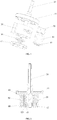
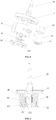
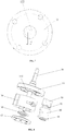
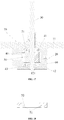
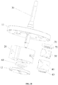
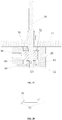
- the above-mentioned figures include following reference signs: 11. upper flange; 111. concave part; 12. lower flange; 121. second position-limiting groove; 122. second extended part; 14. upper position-limiting plate; 20. cylinder; 30. rotation shaft; 40. piston sleeve; 41. first extended part; 42. first position-limiting groove; 43. position-limiting protrusion; 44. step surface; 50. piston; 60. lower friction-reducing ring; 70. upper friction-reducing ring; 71. fifth position-limiting groove; 72. fourth extended part.
- orientation words such as “up”, and “down” are usually used to refer to the orientations shown in the drawings, or to the component itself in the vertical, orthographic or gravity direction.
- orientation words such as “left”, and “right” are usually used to refer to the left and right shown in the drawings, and the orientation words such as “inner”, and “outer” refer to inner and outer relative to the outline of each component itself.
- the above-mentioned orientation words are not given to limit the present application.
- the present application provides a pump body assembly, fluid machinery, and a heat exchange device.
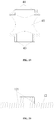
- the pump body assembly includes a lower flange 12, a lower friction-reducing ring 60, a cylinder 20, and a piston assembly.
- the piston assembly is arranged inside the cylinder 20.
- the piston assembly includes a piston sleeve 40, and a piston 50 slidably arranged inside the piston sleeve 40.
- the lower friction-reducing ring 60 has a central hole.
- a position-limiting protrusion 43 is disposed on a surface of the piston sleeve 40, which faces the lower flange 12.
- the position-limiting protrusion 43 extends into the central hole of the lower friction-reducing ring 60, fits and is limited by the lower flange 12, so as to prevent the piston sleeve 40 from moving in a radial direction relative to the lower flange 12.
- the position-limiting protrusion 43 disposed at a lower end of the piston sleeve 40 passes through the central hole of the lower friction-reducing ring 60, fits and is limited by the lower flange 12, thus the lower end of the piston sleeve 40 is limited and supported by the lower flange 12, thereby preventing the piston sleeve 40 from moving in the radial direction during operation, ensuring that the piston sleeve 40 can rotate normally, solving a problem in the prior art that work efficiency of the pump body assembly is affected because the piston sleeve of the pump body assembly is prone to rotate eccentrically, and improving operation reliability and work performance of the pump body assembly.
- a second position-limiting groove 121 is disposed on a surface of the lower flange 12, which faces the piston sleeve 40.
- the position-limiting protrusion 43 extends into the second position-limiting groove 121, so as to prevent the piston sleeve 40 from moving relative to the lower flange 12 in the radial direction.
- the position-limiting protrusion 43 disposed on the piston sleeve 40 extends into the second position-limiting groove 121 of the lower flange 12, and a groove wall of the second position-limiting groove 121 limits and stops a surface of the position-limiting protrusion 43, thus realizing, by the lower flange 12, a position limitation and a stop to the lower end of the piston sleeve 40, and preventing the lower end of the piston sleeve 40 from moving relative to the lower flange 12 in the radial direction.
- the second position-limiting groove 121 is eccentrically arranged on the lower flange 12, and the position-limiting protrusion 43 extends into the second position-limiting groove 121, thus realizing, by the lower flange 12, the position limitation and the stop to the piston sleeve 40.
- the second position-limiting groove 121 is a ring-shaped groove, and an eccentricity of the ring-shaped groove on the lower flange 12 is e.
- the pump body assembly further includes an upper flange 11 disposed above the piston assembly, and the pump body assembly further includes a rotation shaft 30.
- the rotation shaft 30 is provided and passes through the upper flange 11, the piston sleeve 40 and the lower flange 12 in sequence.
- the rotation shaft 30, the upper flange 11, and the lower flange 12 are coaxially arranged.
- the rotation shaft 30 rotates around a central axis of the upper flange 11;
- the piston sleeve 40 rotates around a central axis of a concave part 111;
- the piston 50 only reciprocates relative to the piston sleeve 40, and the piston 50 reciprocates relative to the rotation shaft 30.
- Two reciprocating motions are perpendicular to each other, that is, the operation of the pump body assembly follows a principle of a cross slide block type mechanism.
- the volumes of two cavities formed among a curved surface of a head of the piston 50, an inner surface of the cylinder 20, and a guiding hole of the piston sleeve 40 gradually changes, completing processes of intake, compression and exhausting.
- the present application further provides fluid machinery (not shown), including the above-mentioned pump body assembly.
- the fluid machinery is a compressor.
- the present application further provides a heat exchange device (not shown), including the above-mentioned fluid machinery.
- the heat exchange device is an air conditioner.
- the pump body assembly of the second embodiment differs from that of the first embodiment in that a structure of the lower flange 12 is different.
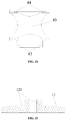
- a second extended part 122 is provided on the surface of the lower flange 12, which faces the piston sleeve 40.
- the second extended part 122 limits and stops the position-limiting protrusion 43, so as to prevent the piston sleeve 40 from moving relative to the lower flange 12 in the radial direction.
- a side surface of the second extended part 122 fits and limits a side surface of the position-limiting protrusion 43 to avoid a radial displacement therebetween, thereby preventing the piston sleeve 40 from moving relative to the lower flange 12 in the radial direction, ensuring the piston sleeve 40 to operate normally, and improving the operation reliability and the work efficiency of the pump body assembly.
- the second extended part 122 is disposed inside the position-limiting protrusion 43. Specifically, an outer side surface of the second extended part 122 limits and stops a side surface of the position-limiting protrusion 43, which is proximate to a center of the piston sleeve 40, to prevent a radial displacement therebetween.
- the first predetermined distance is greater than or equal to 5um, and less than or equal to 40um.
- the above numerical range not only ensures that the second extended part 122 can limit the position-limiting protrusion 43 in the radial direction, but also enables the position-limiting protrusion 43 to rotate relative to the second extended part 122, thereby improving the operation reliability of the pump body assembly.
- the second extended part is located outside the position-limiting protrusion. Specifically, an inner side surface of the second extended part limits and stops a side surface of the position-limiting protrusion, which is far away from the center of the piston sleeve, thereby preventing a radial displacement therebetween.
- the position-limiting protrusion 43 is a protruding ring extending towards the lower flange 12, and the protruding ring and the piston sleeve 40 is coaxially arranged.
- the structure of the position-limiting protrusion 43 is not limited to such.
- the position-limiting protrusion 43 includes a plurality of protruding platforms extending towards the lower flange 12, and the plurality of the protruding platforms are arranged at intervals along a circumference of the piston sleeve 40.
- the second extended part 122 is an eccentric protruding platform, and the eccentricity of the second extended part 122 on the lower flange 12 is e.
- the eccentricity of the pump body assembly is determined in the above manner, which makes it easier to guarantee the eccentricity of the pump body assembly, and the determination of the eccentricity e is more reliable and simpler.
- the pump body assembly of the third embodiment differs from that of the first embodiment in that a structure of the upper flange 11 is different.
- a concave part 111 is provided on a surface of the upper flange 11, which faces the piston sleeve 40.
- a first extended part 41 extends into the concave part 111, and is limited and stopped by the convex part 111 in the radial direction of the piston sleeve 40.
- the first extended part 41 of the piston sleeve 40 extends into the concave part 111 of the upper flange 11, thus realizing, by the upper flange 11, the position limitation to the piston sleeve 40 in the radial direction.
- the convex part 111 limits and stops the first extended part 41, which ensures that the first extended part 41 rotates in the convex part 111, thereby preventing the first extended part 41 from moving in the radial direction, realizing, by the upper flange 11, the position limitation to and a support for the upper end of the piston sleeve 40, and preventing the piston sleeve 40 from rotating eccentrically and aslant.
- the lower end of the piston sleeve 40 is limited and supported by the lower flange 12, thereby making both the upper and lower ends of the piston sleeve 40 to be limited and supported, ensuring the pump body assembly to operate normally, and improving the work reliability of the pump body assembly.
- the first extended part 41 and the concave part 111 are ring-shaped, and the first extended part 41, the concave part 111 and the piston sleeve 40 are coaxially arranged.
- the above arrangement enables the piston sleeve 40 to rotate relative to the upper flange 11, thereby ensuring the operation reliability of the pump body assembly.
- the piston sleeve 40 and the upper flange 11 are eccentrically arranged, and an eccentricity therebetween is an eccentricity e of the pump body assembly.
- the above arrangement enables the first extended part 41 of the piston sleeve 40 to rotate in the concave part 111 of the upper flange 11 and rotate around a center axis of the piston sleeve 40 (or around a center axis of the concave part 111), thus ensuring reliability of the position limitation and the support provided by the upper flange for the piston sleeve 40.
- the structure of the first extended part 41 is not limited to such.
- the first extended part 41 is a double-layered ring-shaped structure, and at least one layer of the ring-shaped structure is limited and stopped by an inner groove wall or an outer groove wall of the concave part 111.
- the above arrangement makes the structure of the first extended part 41 more diversified, thereby making the processing and manufacturing of the piston sleeve 40 easier and simpler, and reducing labor intensity of staff.
- the concave part 111 is a groove.
- the above-mentioned structure is simple, and easy to process and implement.
- a width of the groove is greater than a thickness of the first extended part 41.
- the above arrangement ensures that the first extended part 41 is located in the groove, thereby ensuring that the groove can limit and stop the first extended part 41, improving the reliability of the position limitation provided by the upper flange 11 for the piston sleeve 40, and improving the operation reliability of the pump body assembly.
- the inner groove wall of the groove limits and stops the side surface of the first extended part 41, which is proximate to the center of the piston sleeve 40, thus preventing a radial displacement therebetween.
- the second predetermined distance, between the inner groove wall of the groove and the side surface of the first extended part 41 proximate to the center of the piston sleeve 40, is set, which not only ensures the groove to limit the position of the first extended part 41 in the radial direction, but also enables the first extended part 41 to rotate relative to the groove, thereby improving the operation reliability of the pump body assembly.
- the convex part 111 and the upper flange 11 are eccentrically arranged, and the eccentricity is e.
- the eccentricity of the pump body assembly is determined in the above manner, making it easier to guarantee the eccentricity of the pump body assembly, and the determination of the eccentricity e is more reliable and simpler.
- the pump body assembly of the fourth embodiment differs from that of the third embodiment in that a structure of the pump body assembly is different.
- the pump body assembly further includes an upper flange 11 and an upper friction-reducing ring 70.
- the upper friction-reducing ring 70 is disposed inside the cylinder 20; the upper flange 11 is disposed above the cylinder 20.
- An upper end surface of the piston sleeve 40 fits and is limited by the upper friction-reducing ring 70, so as to prevent the piston sleeve 40 from moving relative to the upper flange 11 in the radial direction.
- the upper end of the piston sleeve 40 is limited and supported by the upper friction-reducing ring 70, thereby preventing the piston sleeve 40 from moving in the radial direction during operation, ensuring that the piston sleeve 40 can rotate normally, solving the problem in the prior art that the work efficiency of the pump body assembly is affected because the piston sleeve of the pump body assembly is prone to rotate eccentrically, and improving the operation reliability and the work performance of the pump body assembly.
- the first extended part 41 is provided on the upper end surface of the piston sleeve 40.
- the first extended part 41 extends into a central hole of the upper friction-reducing ring 70, fits and is limited by an inner surface of the central hole of the upper friction-reducing ring 70.
- the first extended part 41 extends into the central hole of the upper friction-reducing ring 70, fits and is limited by the inner surface of the central hole, thus limiting the upper end of the piston sleeve 40 in the radial direction, preventing the upper end of the piston sleeve 40 from moving relative to the upper flange 11 in the radial direction, and avoiding structural interference between the piston sleeve 40 and the piston 50 or cylinder 20, which will affect the normal operation of the pump body assembly.
- the above-mentioned structure is simple, and easy to process and implement.
- the first extended part 41 is ring-shaped, and the first extended part 41 and the piston sleeve 40 are coaxially arranged.
- the above arrangement enables the piston sleeve 40 to rotate relative to the upper flange 11, thereby ensuring the operation reliability of the pump body assembly.
- the piston sleeve 40 and the upper flange 11 are eccentrically arranged, and the eccentricity therebetween is the eccentricity e of the pump body assembly.
- the above arrangement enables the first extended part 41 of the piston sleeve 40 to rotate inside a central hole of the upper position-limiting plate 14 and rotate around the center axis of the piston sleeve 40, thus ensuring reliability of the position limitation and the support provided by the upper position-limiting plate 14 for the piston sleeve 40.
- a structure of the first extended part 41 is not limited to such.
- the first extended part 41 is a double-layered ring-shaped structure, and an outermost layer ring-shaped structure is limited and stopped by the inner surface of the central hole of the upper position-limiting plate 14.
- the above arrangement makes the structure of the first extended part 41 more diversified, thereby making the processing and manufacturing of the piston sleeve 40 easier and simpler, and reducing the labor intensity of staff.
- the first extended part 41 is a protruding ring, and the protruding ring and the piston sleeve 40 are coaxially arranged.
- the structure of the first extended part 41 is not limited to such.
- the first extended part 41 includes at least one protrusion.
- the multiple protrusions are arranged in a circle and arranged coaxially with the piston sleeve 40.
- the pump body assembly of the fifth embodiment differs from that of the fourth embodiment in that structure of the upper friction-reducing ring 70 and structure of the piston sleeve 40 are different respectively.
- a fifth position-limiting groove 71 is disposed on a surface of the upper friction-reducing ring 70, which faces the piston sleeve 40.
- the first extended part 41 is provided on the upper end surface of the piston sleeve 40. The first extended part 41 extends into the fifth position-limiting groove 71, and is limited and stopped by the fifth position-limiting groove 71.
- the outer surface of the first extended part 41 of the piston sleeve 40 is limited and stopped by a groove wall of the fifth position-limiting groove 71, thereby realizing, by the upper friction-reducing ring 70, the position limitation and a stop to the upper end of the piston sleeve 40, preventing the upper end of the piston sleeve 40 from moving relative to the upper flange 11 in the radial direction, and improving the operation reliability of the pump body assembly.
- the fifth position-limiting groove 71 is a ring-shaped groove.
- the ring-shaped groove and the central hole of the upper friction-reducing ring 70 are coaxially arranged.
- the first extended part 41 is ring-shaped.
- the fifth position-limiting groove 71 and the first extended part 41 are coaxially arranged.
- the pump body assembly of the sixth embodiment differs from that of the fourth embodiment in that the structure of the upper friction-reducing ring 70 is different.
- a fourth extended part 72 is disposed on the surface of the upper friction-reducing ring 70, which faces the piston sleeve 40.
- the fourth extended part 72 extends into the piston sleeve 40, limits and stops the inner surface of the piston sleeve 40.
- a step surface 44 is disposed on the inner surface of the piston sleeve 40, and the fourth extended part 72 extends into and limits the step surface 44, thus realizing, by the upper friction-reducing ring 70, the position limitation to the piston sleeve 40 in the radial direction.
- the fourth extended part 72 is ring-shaped, and the fourth extended part 72 and the central hole of the upper friction-reducing ring 70 are coaxially arranged.
- a structure of the fourth extended part 72 is not limited to such.
- the fourth extended part 72 is a double-layered ring-shaped structure, and an outermost layer ring-shaped structure limits and stops the inner surface of the step surface 44.
- the above arrangement makes the structure of the fourth extended part 72 more diversified, thereby making the processing and the manufacturing of the upper friction-reducing ring 70 easier and simpler, and reducing the labor intensity of staff.
- the pump body assembly of the seventh embodiment differs from that of the fourth embodiment in that the structure of the upper friction-reducing ring 70 and the structure of the piston sleeve 40 are different respectively.
- the fourth extended part 72 is disposed on the surface of the upper friction-reducing ring 70, which faces the piston sleeve 40, and a first position-limiting groove 42 is disposed on the upper end surface of the piston sleeve 40.
- the fourth extended part 72 extends into the first position-limiting groove 42, limits and stops the first position-limiting groove 42.
- the fourth extended part 72 extends into the first position-limiting groove 42, and an outer surface of the fourth extended part 72 limits and stops the groove wall of the first position-limiting groove 42, thus realizing, by the upper friction-reducing ring 70, the position limitation to the piston sleeve 40 in the radial direction.
- the fourth extended part 72 and the first position-limiting groove 42 are ring-shaped, and the fourth extended part 72, the first position-limiting groove 42 and the piston sleeve 40 are coaxially arranged.
- the above-mentioned structure is simple, and easy to implement and process.
- the pump body assembly of the eighth embodiment differs from that of the fourth embodiment in that a structure of the upper flange 11 is different.
- the pump body assembly further includes the upper flange 11 and the upper friction-reducing ring 70; the upper friction-reducing ring 70 is disposed inside the cylinder 20; the upper flange 11 is disposed above the cylinder 20; the upper friction-reducing ring 70 has a central hole; and the first extended part 41 is disposed on the upper end surface of the piston sleeve 40.
- the first extended part 41 extends into the central hole of the upper friction-reducing ring 70, fits and is limited by the lower end surface of the upper flange 11, so as to prevent the piston sleeve 40 from moving relative to the upper flange 11 in the radial direction.
- the first extended part 41 of the piston sleeve 40 extends into the central hole of the upper friction-reducing ring 70, fits and is limited by the lower end surface of the upper flange 11, thus realizing, by the upper flange 11, the position limitation to and the support for the upper end of the piston sleeve 40, further preventing the piston sleeve 40 from moving in the radial direction during operation, ensuring that the piston sleeve 40 can rotate normally, solving the problem in the prior art that the work efficiency of the pump body assembly is affected because the piston sleeve of the pump body assembly is prone to rotate eccentrically, and improving the operation reliability and the work performance of the pump body assembly.
- the concave part 111 is disposed on the surface of the upper flange 11, which faces the piston sleeve 40.
- the first extended part 41 extends into the concave part 111, and is limited and stopped by the convex part 111 in the radial direction of the piston sleeve 40. Specifically, the first extended part 41 passes through the central hole of the upper friction-reducing ring 70, and then extends into the concave part 111.
- the outer surface of the first extended part 41 fits and is limited by the inner surface of the concave part 111, thus realizing, by the upper flange 11, the position limitation and the stop to the upper end of the piston sleeve 40 in the radial direction, and avoiding the structural interference between the piston sleeve 40 and the piston 50 or the cylinder 20, which will affect the normal operation of the pump body assembly.
- the above-mentioned structure is simple, and easy to process and implement.
- the first extended part 41 and the concave part 111 are ring-shaped, and the first extended part 41, the concave part 111 and the piston sleeve 40 are coaxially arranged.
- the above arrangement enables the piston sleeve 40 to rotate relative to the upper flange 11, thereby ensuring the operation reliability of the pump body assembly.
- the piston sleeve 40 and the upper flange 11 are eccentrically arranged, and the eccentricity thereof is the eccentricity e of the pump body assembly.
- the above arrangement enables the first extended part 41 of the piston sleeve 40 to rotate in the concave part 111 of the upper flange 11 and rotate around the center axis of the piston sleeve 40 (or around a center axis of the concave part 111), thus ensuring reliability of the position limitation and the support provided by the upper flange 11 for the piston sleeve 40.
- a structure of the first extended part 41 is not limited to such.
- the first extended part 41 is a double-layered ring-shaped structure, and at least one layer of the ring-shaped structure is limited and stopped by an inner groove wall or an outer groove wall of the concave part 111.
- the above arrangement makes the structure of the first extended part 41 more diversified, thereby making the processing and the manufacturing of the piston sleeve 40 easier and simpler, and reducing the labor intensity of staff.
- the concave part 111 is a groove.
- the above-mentioned structure is simple, and easy to process and implement.
- a width of the groove is greater than a thickness of the first extended part 41.
- the above arrangement ensures that the first extended part 41 is located in the groove, thereby ensuring that the groove can limit and stop the first extended part 41, improving the reliability of the position limitation provided by the upper flange 11 for the piston sleeve 40, and improving the operation reliability of the pump body assembly.
- the lower end surface of the upper flange has a position-limiting portion extending towards the piston sleeve, and the first extended part is limited and stopped by the position-limiting portion, so as to prevent the piston sleeve from moving relative to the upper flange in the radial direction.
- the position-limiting protrusion disposed at the lower end of the piston sleeve passes through the central hole of the lower friction-reducing ring, fits and is limited by the lower flange, thus the lower end of the piston sleeve is limited and supported by the lower flange, thereby preventing the piston sleeve from moving in the radial direction during operation, ensuring that the piston sleeve can rotate normally, solving the problem in the prior art that the work efficiency of the pump body assembly is affected because the piston sleeve of the pump body assembly is prone to rotate eccentrically, and improving the operation reliability and the work performance of the pump body assembly.
Landscapes
- Engineering & Computer Science (AREA)
- General Engineering & Computer Science (AREA)
- Mechanical Engineering (AREA)
- Chemical & Material Sciences (AREA)
- Combustion & Propulsion (AREA)
- Details Of Reciprocating Pumps (AREA)
- Reciprocating Pumps (AREA)
- Compressor (AREA)
- Applications Or Details Of Rotary Compressors (AREA)
Applications Claiming Priority (2)
| Application Number | Priority Date | Filing Date | Title |
|---|---|---|---|
| CN201810792303.XA CN108799104B (zh) | 2018-07-18 | 2018-07-18 | 泵体组件、流体机械及换热设备 |
| PCT/CN2018/120954 WO2020015290A1 (zh) | 2018-07-18 | 2018-12-13 | 泵体组件、流体机械及换热设备 |
Publications (2)
| Publication Number | Publication Date |
|---|---|
| EP3779193A4 EP3779193A4 (de) | 2021-02-17 |
| EP3779193A1 true EP3779193A1 (de) | 2021-02-17 |
Family
ID=64077047
Family Applications (1)
| Application Number | Title | Priority Date | Filing Date |
|---|---|---|---|
| EP18926384.1A Pending EP3779193A1 (de) | 2018-07-18 | 2018-12-13 | Pumpenanordnung, fluidmaschine und wärmeaustauschvorrichtung |
Country Status (5)
| Country | Link |
|---|---|
| US (1) | US11208990B2 (de) |
| EP (1) | EP3779193A1 (de) |
| JP (1) | JP7047134B2 (de) |
| CN (1) | CN108799104B (de) |
| WO (1) | WO2020015290A1 (de) |
Families Citing this family (5)
| Publication number | Priority date | Publication date | Assignee | Title |
|---|---|---|---|---|
| CN108869278B (zh) * | 2018-07-18 | 2023-12-08 | 珠海格力电器股份有限公司 | 泵体组件、流体机械及换热设备 |
| CN108799104B (zh) | 2018-07-18 | 2024-04-02 | 珠海格力电器股份有限公司 | 泵体组件、流体机械及换热设备 |
| CN108916045B (zh) * | 2018-07-18 | 2024-04-02 | 珠海格力电器股份有限公司 | 泵体组件、流体机械及换热设备 |
| CN109555691B (zh) * | 2018-12-18 | 2024-07-12 | 珠海格力电器股份有限公司 | 活塞限位结构、压缩机及换热设备 |
| CN109555693B (zh) * | 2018-12-18 | 2024-12-06 | 珠海格力节能环保制冷技术研究中心有限公司 | 活塞限位结构、压缩机及换热设备 |
Family Cites Families (22)
| Publication number | Priority date | Publication date | Assignee | Title |
|---|---|---|---|---|
| JPS59155580A (ja) * | 1983-02-25 | 1984-09-04 | Hitachi Ltd | 容量制御型圧縮機 |
| DE3520662A1 (de) * | 1985-06-08 | 1987-01-02 | Rudolf Paul Fritsch | Wellendichtung fuer eine vorrichtung zur kontinuierlichen verarbeitung hochviskoser medien, insbesondere zur herstellung hochmolekularer polymere |
| JPH1113647A (ja) * | 1997-06-27 | 1999-01-19 | Kayseven Co Ltd | ポンプ |
| DE10217228C1 (de) | 2002-04-18 | 2003-10-23 | Enginion Ag | Flügelzellenmaschine für ein dampf- oder gasförmiges Arbeitsmedium |
| JP4598098B2 (ja) * | 2008-03-13 | 2010-12-15 | 日立オートモティブシステムズ株式会社 | ギヤポンプのシール装置 |
| DE212012000062U1 (de) * | 2011-02-25 | 2013-10-14 | Neo Mechanics Ltd. | Mit einer spiralförmig gewalkten Dichtung abgedichteter Kolben eines Hydraulikzylinders |
| CN202510226U (zh) | 2012-04-01 | 2012-10-31 | 深圳市特尔佳科技股份有限公司 | 发动机制动器 |
| CN204877939U (zh) * | 2015-08-07 | 2015-12-16 | 珠海格力节能环保制冷技术研究中心有限公司 | 流体机械和换热设备 |
| CN105570130B (zh) * | 2016-02-16 | 2018-11-27 | 珠海格力节能环保制冷技术研究中心有限公司 | 压缩机泵体结构和压缩机 |
| CN105604937B (zh) * | 2016-02-18 | 2018-06-26 | 珠海格力节能环保制冷技术研究中心有限公司 | 流体机械和换热设备 |
| CN106089717A (zh) * | 2016-07-28 | 2016-11-09 | 珠海格力节能环保制冷技术研究中心有限公司 | 一种压缩机泵体及压缩机 |
| CN106870361B (zh) | 2017-03-30 | 2018-12-07 | 珠海格力电器股份有限公司 | 泵体组件、压缩机及换热系统 |
| CN107435634B (zh) * | 2017-07-31 | 2023-03-21 | 珠海格力节能环保制冷技术研究中心有限公司 | 一种压缩机泵体和压缩机以及压缩机泵体的装配方法 |
| DE102017216002A1 (de) * | 2017-09-12 | 2019-03-14 | Robert Bosch Gmbh | Pumpenanordnung für ein Hydraulikaggregat mit einem Pumpenkolben |
| CN108799107B (zh) | 2018-07-18 | 2024-06-18 | 珠海格力电器股份有限公司 | 泵体组件、流体机械及换热设备 |
| CN108799106B (zh) | 2018-07-18 | 2024-08-20 | 珠海格力电器股份有限公司 | 泵体组件、流体机械及换热设备 |
| CN208474108U (zh) * | 2018-07-18 | 2019-02-05 | 珠海格力电器股份有限公司 | 泵体组件、流体机械及换热设备 |
| CN108799105B (zh) | 2018-07-18 | 2023-10-03 | 珠海格力电器股份有限公司 | 泵体组件、流体机械及换热设备 |
| CN108869279B (zh) | 2018-07-18 | 2024-04-16 | 珠海格力电器股份有限公司 | 泵体组件、流体机械及换热设备 |
| CN108869278B (zh) | 2018-07-18 | 2023-12-08 | 珠海格力电器股份有限公司 | 泵体组件、流体机械及换热设备 |
| CN108799104B (zh) | 2018-07-18 | 2024-04-02 | 珠海格力电器股份有限公司 | 泵体组件、流体机械及换热设备 |
| CN108799108B (zh) | 2018-07-18 | 2024-06-18 | 珠海格力电器股份有限公司 | 泵体组件、流体机械及换热设备 |
-
2018
- 2018-07-18 CN CN201810792303.XA patent/CN108799104B/zh active Active
- 2018-12-13 US US17/059,119 patent/US11208990B2/en active Active
- 2018-12-13 JP JP2020561917A patent/JP7047134B2/ja active Active
- 2018-12-13 WO PCT/CN2018/120954 patent/WO2020015290A1/zh not_active Ceased
- 2018-12-13 EP EP18926384.1A patent/EP3779193A1/de active Pending
Also Published As
| Publication number | Publication date |
|---|---|
| CN108799104B (zh) | 2024-04-02 |
| EP3779193A4 (de) | 2021-02-17 |
| WO2020015290A1 (zh) | 2020-01-23 |
| JP2021528585A (ja) | 2021-10-21 |
| JP7047134B2 (ja) | 2022-04-04 |
| US20210207590A1 (en) | 2021-07-08 |
| CN108799104A (zh) | 2018-11-13 |
| US11208990B2 (en) | 2021-12-28 |
Similar Documents
| Publication | Publication Date | Title |
|---|---|---|
| EP3779193A1 (de) | Pumpenanordnung, fluidmaschine und wärmeaustauschvorrichtung | |
| EP3779197B1 (de) | Pumpenkörperanordnung, strömungsmaschine und wärmeaustauschvorrichtung | |
| CN211397889U (zh) | 泵体组件、流体机械及换热设备 | |
| CN108799103B (zh) | 泵体组件、流体机械及换热设备 | |
| US12135020B2 (en) | Pump body, compressor, and heat exchange apparatus | |
| CN117145772B (zh) | 流体机械和换热设备 | |
| CN116241470A (zh) | 流体机械、换热设备和流体机械的运行方法 | |
| CN108799108B (zh) | 泵体组件、流体机械及换热设备 | |
| JP2022548492A (ja) | ポンプ本体アセンブリ、熱交換機器、流体機械及びその動作方法 | |
| CN108799105B (zh) | 泵体组件、流体机械及换热设备 | |
| CN109072889A (zh) | 一种液压装置 | |
| EP2832997B1 (de) | Taumelscheibe | |
| CN108869279B (zh) | 泵体组件、流体机械及换热设备 | |
| CN108799106B (zh) | 泵体组件、流体机械及换热设备 | |
| CN108799109A (zh) | 泵体组件、流体机械及换热设备 | |
| WO2020125108A1 (zh) | 活塞限位结构、压缩机及换热设备 | |
| CN107035693B (zh) | 驱动主轴和压缩机 | |
| CN110905808B (zh) | 泵体组件、流体机械和换热设备 | |
| CN110985380A (zh) | 泵体组件、流体机械及换热设备 | |
| CN117145766B (zh) | 流体机械和换热设备 | |
| CN108799107B (zh) | 泵体组件、流体机械及换热设备 | |
| CN211397891U (zh) | 泵体组件、流体机械及换热设备 | |
| CN108916046B (zh) | 泵体组件、流体机械及换热设备 | |
| CN206770214U (zh) | 驱动主轴和压缩机 | |
| CN206221272U (zh) | 偏心调节机构及具有其的压缩机 |
Legal Events
| Date | Code | Title | Description |
|---|---|---|---|
| STAA | Information on the status of an ep patent application or granted ep patent |
Free format text: STATUS: THE INTERNATIONAL PUBLICATION HAS BEEN MADE |
|
| PUAI | Public reference made under article 153(3) epc to a published international application that has entered the european phase |
Free format text: ORIGINAL CODE: 0009012 |
|
| STAA | Information on the status of an ep patent application or granted ep patent |
Free format text: STATUS: REQUEST FOR EXAMINATION WAS MADE |
|
| 17P | Request for examination filed |
Effective date: 20201111 |
|
| A4 | Supplementary search report drawn up and despatched |
Effective date: 20201217 |
|
| AK | Designated contracting states |
Kind code of ref document: A1 Designated state(s): AL AT BE BG CH CY CZ DE DK EE ES FI FR GB GR HR HU IE IS IT LI LT LU LV MC MK MT NL NO PL PT RO RS SE SI SK SM TR |
|
| AX | Request for extension of the european patent |
Extension state: BA ME |
|
| DAV | Request for validation of the european patent (deleted) | ||
| DAX | Request for extension of the european patent (deleted) | ||
| STAA | Information on the status of an ep patent application or granted ep patent |
Free format text: STATUS: EXAMINATION IS IN PROGRESS |
|
| 17Q | First examination report despatched |
Effective date: 20230526 |
|
| P01 | Opt-out of the competence of the unified patent court (upc) registered |
Effective date: 20230530 |
|
| GRAP | Despatch of communication of intention to grant a patent |
Free format text: ORIGINAL CODE: EPIDOSNIGR1 |
|
| STAA | Information on the status of an ep patent application or granted ep patent |
Free format text: STATUS: GRANT OF PATENT IS INTENDED |