EP3779209B1 - Engin moteur autonome sur une surface de sol solide avec un groupe hydraulique monté sur un châssis - Google Patents
Engin moteur autonome sur une surface de sol solide avec un groupe hydraulique monté sur un châssis Download PDFInfo
- Publication number
- EP3779209B1 EP3779209B1 EP19405013.4A EP19405013A EP3779209B1 EP 3779209 B1 EP3779209 B1 EP 3779209B1 EP 19405013 A EP19405013 A EP 19405013A EP 3779209 B1 EP3779209 B1 EP 3779209B1
- Authority
- EP
- European Patent Office
- Prior art keywords
- container
- fluid
- machine according
- closure plate
- hydraulic
- Prior art date
- Legal status (The legal status is an assumption and is not a legal conclusion. Google has not performed a legal analysis and makes no representation as to the accuracy of the status listed.)
- Active
Links
Images


Classifications
-
- F—MECHANICAL ENGINEERING; LIGHTING; HEATING; WEAPONS; BLASTING
- F15—FLUID-PRESSURE ACTUATORS; HYDRAULICS OR PNEUMATICS IN GENERAL
- F15B—SYSTEMS ACTING BY MEANS OF FLUIDS IN GENERAL; FLUID-PRESSURE ACTUATORS, e.g. SERVOMOTORS; DETAILS OF FLUID-PRESSURE SYSTEMS, NOT OTHERWISE PROVIDED FOR
- F15B1/00—Installations or systems with accumulators; Supply reservoir or sump assemblies
- F15B1/26—Supply reservoir or sump assemblies
-
- B—PERFORMING OPERATIONS; TRANSPORTING
- B66—HOISTING; LIFTING; HAULING
- B66F—HOISTING, LIFTING, HAULING OR PUSHING, NOT OTHERWISE PROVIDED FOR, e.g. DEVICES WHICH APPLY A LIFTING OR PUSHING FORCE DIRECTLY TO THE SURFACE OF A LOAD
- B66F9/00—Devices for lifting or lowering bulky or heavy goods for loading or unloading purposes
- B66F9/06—Devices for lifting or lowering bulky or heavy goods for loading or unloading purposes movable, with their loads, on wheels or the like, e.g. fork-lift trucks
- B66F9/075—Constructional features or details
- B66F9/07513—Details concerning the chassis
- B66F9/07518—Fuel or oil tank arrangements
-
- B—PERFORMING OPERATIONS; TRANSPORTING
- B66—HOISTING; LIFTING; HAULING
- B66F—HOISTING, LIFTING, HAULING OR PUSHING, NOT OTHERWISE PROVIDED FOR, e.g. DEVICES WHICH APPLY A LIFTING OR PUSHING FORCE DIRECTLY TO THE SURFACE OF A LOAD
- B66F9/00—Devices for lifting or lowering bulky or heavy goods for loading or unloading purposes
- B66F9/06—Devices for lifting or lowering bulky or heavy goods for loading or unloading purposes movable, with their loads, on wheels or the like, e.g. fork-lift trucks
- B66F9/075—Constructional features or details
- B66F9/07572—Propulsion arrangements
-
- F—MECHANICAL ENGINEERING; LIGHTING; HEATING; WEAPONS; BLASTING
- F04—POSITIVE - DISPLACEMENT MACHINES FOR LIQUIDS; PUMPS FOR LIQUIDS OR ELASTIC FLUIDS
- F04B—POSITIVE-DISPLACEMENT MACHINES FOR LIQUIDS; PUMPS
- F04B17/00—Pumps characterised by combination with, or adaptation to, specific driving engines or motors
- F04B17/03—Pumps characterised by combination with, or adaptation to, specific driving engines or motors driven by electric motors
-
- F—MECHANICAL ENGINEERING; LIGHTING; HEATING; WEAPONS; BLASTING
- F04—POSITIVE - DISPLACEMENT MACHINES FOR LIQUIDS; PUMPS FOR LIQUIDS OR ELASTIC FLUIDS
- F04B—POSITIVE-DISPLACEMENT MACHINES FOR LIQUIDS; PUMPS
- F04B23/00—Pumping installations or systems
- F04B23/02—Pumping installations or systems having reservoirs
- F04B23/025—Pumping installations or systems having reservoirs the pump being located directly adjacent the reservoir
- F04B23/028—Pumping installations or systems having reservoirs the pump being located directly adjacent the reservoir the pump being mounted on top of the reservoir
-
- F—MECHANICAL ENGINEERING; LIGHTING; HEATING; WEAPONS; BLASTING
- F15—FLUID-PRESSURE ACTUATORS; HYDRAULICS OR PNEUMATICS IN GENERAL
- F15B—SYSTEMS ACTING BY MEANS OF FLUIDS IN GENERAL; FLUID-PRESSURE ACTUATORS, e.g. SERVOMOTORS; DETAILS OF FLUID-PRESSURE SYSTEMS, NOT OTHERWISE PROVIDED FOR
- F15B21/00—Common features of fluid actuator systems; Fluid-pressure actuator systems or details thereof, not covered by any other group of this subclass
- F15B21/005—Filling or draining of fluid systems
-
- F—MECHANICAL ENGINEERING; LIGHTING; HEATING; WEAPONS; BLASTING
- F15—FLUID-PRESSURE ACTUATORS; HYDRAULICS OR PNEUMATICS IN GENERAL
- F15B—SYSTEMS ACTING BY MEANS OF FLUIDS IN GENERAL; FLUID-PRESSURE ACTUATORS, e.g. SERVOMOTORS; DETAILS OF FLUID-PRESSURE SYSTEMS, NOT OTHERWISE PROVIDED FOR
- F15B21/00—Common features of fluid actuator systems; Fluid-pressure actuator systems or details thereof, not covered by any other group of this subclass
- F15B21/04—Special measures taken in connection with the properties of the fluid
- F15B21/042—Controlling the temperature of the fluid
- F15B21/0423—Cooling
-
- F—MECHANICAL ENGINEERING; LIGHTING; HEATING; WEAPONS; BLASTING
- F15—FLUID-PRESSURE ACTUATORS; HYDRAULICS OR PNEUMATICS IN GENERAL
- F15B—SYSTEMS ACTING BY MEANS OF FLUIDS IN GENERAL; FLUID-PRESSURE ACTUATORS, e.g. SERVOMOTORS; DETAILS OF FLUID-PRESSURE SYSTEMS, NOT OTHERWISE PROVIDED FOR
- F15B21/00—Common features of fluid actuator systems; Fluid-pressure actuator systems or details thereof, not covered by any other group of this subclass
- F15B21/04—Special measures taken in connection with the properties of the fluid
- F15B21/048—Arrangements for compressed air preparation, e.g. comprising air driers, air condensers, filters, lubricators or pressure regulators
-
- F—MECHANICAL ENGINEERING; LIGHTING; HEATING; WEAPONS; BLASTING
- F15—FLUID-PRESSURE ACTUATORS; HYDRAULICS OR PNEUMATICS IN GENERAL
- F15B—SYSTEMS ACTING BY MEANS OF FLUIDS IN GENERAL; FLUID-PRESSURE ACTUATORS, e.g. SERVOMOTORS; DETAILS OF FLUID-PRESSURE SYSTEMS, NOT OTHERWISE PROVIDED FOR
- F15B2211/00—Circuits for servomotor systems
- F15B2211/20—Fluid pressure source, e.g. accumulator or variable axial piston pump
- F15B2211/205—Systems with pumps
- F15B2211/20507—Type of prime mover
- F15B2211/20515—Electric motor
-
- F—MECHANICAL ENGINEERING; LIGHTING; HEATING; WEAPONS; BLASTING
- F15—FLUID-PRESSURE ACTUATORS; HYDRAULICS OR PNEUMATICS IN GENERAL
- F15B—SYSTEMS ACTING BY MEANS OF FLUIDS IN GENERAL; FLUID-PRESSURE ACTUATORS, e.g. SERVOMOTORS; DETAILS OF FLUID-PRESSURE SYSTEMS, NOT OTHERWISE PROVIDED FOR
- F15B2211/00—Circuits for servomotor systems
- F15B2211/60—Circuit components or control therefor
- F15B2211/615—Filtering means
-
- F—MECHANICAL ENGINEERING; LIGHTING; HEATING; WEAPONS; BLASTING
- F15—FLUID-PRESSURE ACTUATORS; HYDRAULICS OR PNEUMATICS IN GENERAL
- F15B—SYSTEMS ACTING BY MEANS OF FLUIDS IN GENERAL; FLUID-PRESSURE ACTUATORS, e.g. SERVOMOTORS; DETAILS OF FLUID-PRESSURE SYSTEMS, NOT OTHERWISE PROVIDED FOR
- F15B2211/00—Circuits for servomotor systems
- F15B2211/60—Circuit components or control therefor
- F15B2211/62—Cooling or heating means
Definitions
- the invention relates to a work machine that is self-propelled on a solid ground surface and has a hydraulic unit mounted on a chassis for operating the work machine by pumped hydraulic fluid as a power transmission means, the hydraulic unit consisting of a liquid tank provided for receiving the hydraulic fluid and at least one for removing it from the latter and returning the hydraulic fluid via a liquid return line of the hydraulic fluid into the liquid tank, preferably electrically driven feed pump, as well as a switching valve arrangement that can be controlled between the feed pump and at least one rotary and / or linearly driven consumer of the work machine, which are arranged on the liquid tank, the liquid tank being formed from a container that is open at the top is and the feed pump and the switching valve arrangement connected to it, the connecting lines of the unit components and a liquid filling opening are arranged as a unit on a closure plate that closes the container opening, the closure plate being formed from a metallic material, preferably from structural steel, and the container being formed in one piece.
- the motor pump unit is attached directly/immediately to the tank via a tank opening
- the return filter which has an elongated filter housing for a filter element with a filter cartridge, is inserted into a tank opening intended for it in the tank and has a hose connection and an outlet opening , wherein the filter element is arranged in the flow path between the hose connection and the outlet opening, and a return hose that connects the motor pump unit and the hose connection within the tank.
- Liquid tanks made of metal primarily structural steel, are known as hydraulic units and are formed by welding with feed pumps, valve blocks and filters as well as a filler neck.
- a built-up hydraulic unit with a sheet metal tank made of structural steel is relatively heavy and, with complex chassis and body shapes such as those formed on the outer contour of a vehicle, for example in the wheel arch area, very expensive to produce.
- a welded liquid tank is susceptible to corrosion, particularly after damage to the surface, and stresses around the weld seams lead to leaks.
- a plastic tank has a significant disadvantage when integrating attached aggregation components, such as motors, pumps and valve combinations, especially since the required fastening structures, for example insert frames, can only be implemented in narrow dimensions due to the different expansion coefficients of metal and plastic, because temperature fluctuations lead to a reduction in stability and loss of rigidity , lead to leaks between the insert frames and the plastic tank and weaken the existing strength.
- WO 2017/005338 A1 discloses a hydraulic unit, the electric motor and the hydraulic pump of which are flanged to a first structural unit serving as a supporting device.
- the latter is formed by a metallic molded body which is accommodated in a seat which is formed in the top of a second structural unit formed by a plate-like plastic body.
- This forms a kind of tank cap for the upper open side of the tank of the hydraulic unit.
- the material of the tank is not specified.
- WO 99/13229 A1 discloses an embodiment of a hydraulic unit in which the tank is open at the top and closed by a tank cap. The material of these two parts is not specified.
- the tank is made in one piece from plastic with a connection opening for a housing part of the pump.
- the tank made of plastic is formed in one piece, with the pump lines being connected through a circular pipe socket formed on the upper top wall of the tank.
- DE 10 2016 101 662 A1 relates to a flow line for a pump device of a motor vehicle with flow elements arranged in the flow line. Also revealed US 6,116,454 A a hydraulic oil tank for a work machine with a flow guide element arranged in the tank.
- the present invention has set itself the task of developing a hydraulic unit that has a high level of reliability in use, allows easy assembly when setting up the affected unit components and proves to be robust over a long period of use, and it is intended the susceptibility to wear and the risk of leakage can be largely eliminated.
- the object was achieved in that the container is manufactured with plastic using the rotational molding or injection molding process and the container is box-shaped and has a container end shaped according to a section of a wheel arch of the mobile work machine.
- the solution according to the invention is intended to provide the hydraulic unit with a high quality of functions and greater precision among the aggregation components as well as simple assembly of the unit components built on the closure plate.
- the unit components can be assembled away from the container and tested for function and then installed together on the closure plate of the liquid tank in the container or removed from it individually or together for maintenance and/or repair.
- the hydraulic fluid flowing back into the fluid tank after use is returned via a fluid return line, which is preferably provided with a return filter at the end.
- an outer wall of the container can form a supplementary part of the vehicle body (body part) of the work machine.
- the closure plate which also serves as a cover for the container, is made of a metallic material, preferably made of structural steel, for example a sheet steel or the like, for high stability of the hydraulic unit on the chassis of the work machine and provides a large-area, torsion-resistant connection to the liquid container.
- the upper end or The connecting end of the container to the closure plate is formed by a fastening device provided for sealing between the container and the closure plate.
- the open edge of which can be reinforced for a tight connection to the attached closure plate.
- the feed pump(s), which form a unit and form a unit, the switching valve arrangement, the liquid filter protruding into the liquid tank, the connecting lines and screw connections and other fittings as well as a liquid filler neck are advantageously attached to the closure plate and thus facilitate assembly and disassembly as a unit maintenance work and controls.
- the container is designed in one piece, but also fulfills its relevant function and task in a two-part design.
- the container can also be made from plastic using a different process, which proves to be a durable material and resistant to corrosion and impact situations.
- the liquid filling opening is preferably formed by a filling and venting filter which projects into the liquid-free space of the liquid tank and is attached to the underside of the closure plate.
- the container is box-like and is equipped with a container end shaped like a section of a wheel arch of the mobile work machine, so that it can be attached to the chassis in a space- and weight-saving manner and is easily accessible from the outside.
- a filling and venting filter is preferably arranged in the liquid tank above a certain liquid level so that it can optimally develop its effect.
- the container below the feed pump(s) immersed in the liquid has a container constriction that connects the container into two container spaces, which protrudes from the bottom of the container upwards into the container and ends approximately below the aggregate components, whereby in the container spaces a mixing of the stored cooled liquid with the returned warmer liquid quantity can be achieved.
- the container constriction is formed by at least one flow threshold that distinguishes/divides the liquid tank into a liquid return flow and a container space assigned to the liquid suction, through which a laminar mixture of the returned and the resting hydraulic liquid is achieved.
- the flow threshold(s) can be provided on a rear wall of a cavity placed in the container and thus promote a heat balancing effect.
- a suction opening of the suction line connected to the feed pump(s) is advantageously arranged in the container space at a lower liquid temperature than in the other container space of the liquid tank.
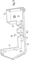
- Fig. 1 shows a spatially represented hydraulic unit 2 built on a chassis of a self-propelled work machine 1 for generating work force/performance by means of a circulating hydraulic fluid.
- the hydraulic unit 2 consists of a container 3 intended to hold the hydraulic fluid, made of plastic, for example made of fiber-crosslinked polyethylene, polyamide or similar material, which is produced in a rotational molding or injection molding process, advantageously in more complex shapes that are closer to the purpose, more cost-effective and with lower weight and appropriate rigidity compared to a tank made of welded steel sheets.
- At least one feed pump 11, 12 is provided, which is arranged inside the fluid tank and is screwed onto a preferably flat closure plate 6 which is fastened to the upper opening of the container 3 and forms a closed fluid tank 5.
- This serves to position and fasten the actuating elements or components of the hydraulic unit 2 as a furnishing unit and can be placed on the container edge 7 defining the upper opening of the container 3 and fastened to hold the liquid tank 5 tightly.
- screws 8 or comparable similar fastening elements are provided, which are anchored at the front in the container edge 7.
- FIG. 1 and 2 show Fig. 1 and 2 a switching valve arrangement 13 attached to the closure plate 6 for controlling the hydraulic fluid or of the unit components, and opposite, laterally offset from the electric motor of the feed pumps 11, 12, a filling and venting filter 14, which projects into the liquid tank 5 and is designed for filling the latter, and a service cover 15, respectively.
- closing flange to which a return filter 20 which projects into the liquid tank 5 and is connected to the liquid return line 18 is attached.
- the closure plate 6 which is made of a metallic material, for example structural steel, offers a high level of rigidity over the plate extension and, together with the container 3, exerts robust stability and rigidity on the liquid tank 5. In terms of manufacturing technology, the closure plate does not pose any high demands.
- the flat extension/extension of the closure plate 6 allows a simple design and arrangement of the unit components, the construction of which can be carried out on the closure plate 6 using simple machine elements and work equipment.
- the shape of the closure plate 6 is suitable for a tight connection with the container 3 at the container edge 7.
- the unit components can be easily detached/removed from the locking plate 6 for maintenance, repair or replacement.
- the container 3 is made in one piece and is manufactured with plastic using rotational molding or an injection molding process.
- a container 3 made of sheet steel can also be used.
- the container 3 is box-shaped so that it can be installed in a space-saving manner on/into the chassis 16 of the self-propelled machine and is easily accessible.
- the container 3 of the liquid tank 5 is in the immediate vicinity of a wheel arch 17 of a rigid or a steerable front or rear axle of the mobile work machine 1, based on the geometry of the wheel arch shape. concentric to the wheel axis ( Fig. 2 ).
- the unit components 11, 12, 13, 14, 15 as well as the liquid lines of the system can be individually removed from the closure plate 6, be it for maintenance, repair or replacement.
- the return filter 20 is preferably part of the equipment of the hydraulic unit 2 and is attached to the closure plate 6 so that it projects into the liquid tank 5, the liquid return line 18, preferably at its end opening into the liquid tank 5, having an outlet opening, for example below the liquid level 19, is trained.
- the return filter 20, equipped with a filter cartridge, is connected at the upper end to the liquid return line 18 (see Fig. 2 ).
- the in Fig. 1 The illustrated service cover (flange) 15 for replacing or maintaining the return filter 20 lies above an invisible filling opening, which is usually extended by a filler neck projecting into the liquid tank 5.
- the liquid tank 5 is divided into two unseparated container spaces 22, 23 by a constriction provided in the container 3 by means of a threshold arrangement 21.
- a threshold arrangement 21 This is in the Fig. 2 and 3 It can be seen that a lower wall part of the rear container wall 24 is offset towards the front wall 25 of the container 3 and extends to a height below the aggregate components or the liquid level 19, and thus forms a cavity 26.
- the side walls 27, 28 and roof-like ceiling elements 29, 30 complete the cavity 26, on the back of which, container wall part 24, a pair of laterally spaced, strip-like flow thresholds 31, 32 protruding against the front container wall 25 are arranged.
- the hydraulic fluid flowing back from the working devices of the working machine 1 into the liquid tank 5 only flows to a small part of the container space 22 via the threshold device 31, 32 into the laterally adjacent container space 23 which is assigned to the suction line 34 of the feed pump (s) 11, 12.
- the larger part flows into the upper common area and mixes with the oil calmed in the liquid tank 5 and cools down slightly, with the suction opening 34 being arranged in the container space 23 with the lower liquid temperature.
- the flow thresholds 31, 32 are attached parallel to each other and running upwards on the back of the rear container wall 24.
- Fig. 2 Additionally, it conveys the routing of the hydraulic fluid among the unit components and the consumers (not shown).
- the already mentioned suction line 34 carries the hydraulic fluid by means of feed pumps 11, 12 separately through the pressure lines 36, 37 via the controllable switching valve arrangement 13 to the consumers or working devices of the work machine 1 and from there via the switching valve arrangement 13 and liquid return line 18 and return filter 20 into the container space 22 respectively. the liquid tank 5.
Landscapes
- Engineering & Computer Science (AREA)
- Transportation (AREA)
- Structural Engineering (AREA)
- Mechanical Engineering (AREA)
- Civil Engineering (AREA)
- Life Sciences & Earth Sciences (AREA)
- Geology (AREA)
- General Engineering & Computer Science (AREA)
- Physics & Mathematics (AREA)
- Fluid Mechanics (AREA)
- Chemical & Material Sciences (AREA)
- Combustion & Propulsion (AREA)
- Supply Devices, Intensifiers, Converters, And Telemotors (AREA)
Claims (14)
- Engin (1) automobile sur sol solide comportant un groupe hydraulique (2) monté sur un châssis (16) et destiné à entraîner l'engin (1) au moyen d'un fluide hydraulique pompé comme agent de transmission de puissance, ledit groupe hydraulique (2) consistant en : un réservoir de fluide (5) destiné à recevoir le fluide hydraulique, et au moins une pompe d'alimentation (11, 12), de préférence à entraînement électrique, raccordée pour prélever le fluide hydraulique de ce dernier et le faire recirculer dans une conduite de recirculation de fluide (18) dans le réservoir de fluide (5), ainsi qu'un actionneur (13) pilotable entre la pompe d'alimentation (11, 12) et au moins un consommateur de l'engin (1) entraîné en rotation et/ou linéaire, lesquels sont agencés sur le réservoir de fluide (5), ledit réservoir de fluide (5) étant constitué d'un conteneur (3) ouvert sur le haut, et ladite pompe d'alimentation (11, 12) ainsi que l'actionneur (13) relié à celle-ci par conduite, lesdites conduites de liaison des composants du groupe hydraulique ainsi qu'une ouverture de remplissage de fluide (15) étant agencées sous la forme d'une unité sur une plaque de fermeture (6) fermant l'ouverture du conteneur, ladite plaque de fermeture (6) étant constituée d'un matériau métallique, de préférence d'acier de construction, et ledit conteneur (3) étant conçu d'une seule pièce, caractérisé en ce que le conteneur (3) est en plastique et réalisé par rotomoulage ou moulage par injection et le conteneur (3) est en forme de caisson et conçu avec une extrémité formée à la manière d'une section partielle d'un passage de roue de l'engin (1) mobile.
- Engin selon la revendication 1, caractérisé en ce que l'extrémité supérieure du conteneur (3) présente un rebord (7) conçu pour une liaison étroite de la plaque de fermeture (6) au conteneur (3).
- Engin selon la revendication 1 ou 2, caractérisé en ce que les composants (4, 11, 12, 13, 14, 15, 18, 34, 36, 37) du groupe hydraulique sont fixés à la plaque de fermeture (6).
- Engin selon l'une des revendications précédentes, caractérisé en ce que l'extrémité du conteneur qui est tournée vers le passage de roue est agencée sur le châssis (16) de façon quelque peu concentrique à la roue de l'engin (1) concernée.
- Engin selon l'une des revendications 1 à 4, caractérisé en ce que l'ouverture de remplissage de fluide (15) est réalisée à travers un filtre de remplissage et de mise à l'air libre (14) pénétrant dans l'espace du réservoir de fluide (5) qui est exempt de fluide.
- Engin selon l'une des revendications précédentes 1 à 5, caractérisé en ce que les composants du groupe hydraulique sont chacun fixés de manière amovible à la plaque de fermeture (6).
- Engin selon la revendication 5, caractérisé en ce que le filtre de remplissage et de mise à l'air libre (14) est disposé dans le réservoir de fluide (5), au-dessus du niveau (19) du fluide hydraulique présent dans le réservoir de fluide hydraulique (5).
- Engin selon l'une des revendications 1 à 7, caractérisé en ce que la conduite de recirculation de fluide (18) se termine par un filtre de retour (20).
- Engin selon la revendication 8, caractérisé en ce que le filtre de retour (20) est fixé à un couvercle (15) en forme de flasque fermant une ouverture d'entretien réalisée dans la plaque de fermeture (6).
- Engin selon l'une des revendications 1 à 9, caractérisé en ce que le conteneur (3) présente, sous la pompe d'alimentation (11, 12) plongée dans le fluide, un resserrement (33) reliant le conteneur (3) en deux espaces de conteneur (22, 23), lequel resserrement s'étend vers le haut, vers l'intérieur du conteneur (3), à partir du fond du conteneur et se termine à peu près sous les composants du groupe hydraulique.
- Engin selon la revendication 10, caractérisé en ce que le resserrement (33) du conteneur est constitué par au moins un seuil d'écoulement (31, 32) différenciant le réservoir de fluide (5) en des espaces de conteneur (22, 23) dont l'un est associé à la recirculation du fluide et l'autre à la consommation du fluide.
- Engin selon la revendication 11, caractérisé en ce que le seuil d'écoulement (31, 32) est prévu dans une paroi arrière de la cavité (26) s'élevant dans le conteneur (3).
- Engin selon l'une des revendications 10 à 12, caractérisé en ce qu'un orifice d'aspiration (35) d'une conduite d'aspiration (34) reliée à la pompe d'alimentation (11, 12) est agencé dans l'espace (23) du conteneur présentant une moindre température de fluide.
- Engin selon l'une des revendications 10 à 13, caractérisé en ce que des conduites de fluide (18, 35, 36) reliant les composants du groupe hydraulique (2) sont suspendues sous la plaque de fermeture (6).
Priority Applications (2)
| Application Number | Priority Date | Filing Date | Title |
|---|---|---|---|
| ES19405013T ES2958107T3 (es) | 2019-08-16 | 2019-08-16 | Máquina de trabajo autopropulsada sobre una superficie de suelo firme, con un grupo hidráulico montado sobre un bastidor para accionar la máquina de trabajo |
| EP19405013.4A EP3779209B1 (fr) | 2019-08-16 | 2019-08-16 | Engin moteur autonome sur une surface de sol solide avec un groupe hydraulique monté sur un châssis |
Applications Claiming Priority (1)
| Application Number | Priority Date | Filing Date | Title |
|---|---|---|---|
| EP19405013.4A EP3779209B1 (fr) | 2019-08-16 | 2019-08-16 | Engin moteur autonome sur une surface de sol solide avec un groupe hydraulique monté sur un châssis |
Publications (2)
| Publication Number | Publication Date |
|---|---|
| EP3779209A1 EP3779209A1 (fr) | 2021-02-17 |
| EP3779209B1 true EP3779209B1 (fr) | 2023-09-20 |
Family
ID=67777274
Family Applications (1)
| Application Number | Title | Priority Date | Filing Date |
|---|---|---|---|
| EP19405013.4A Active EP3779209B1 (fr) | 2019-08-16 | 2019-08-16 | Engin moteur autonome sur une surface de sol solide avec un groupe hydraulique monté sur un châssis |
Country Status (2)
| Country | Link |
|---|---|
| EP (1) | EP3779209B1 (fr) |
| ES (1) | ES2958107T3 (fr) |
Cited By (2)
| Publication number | Priority date | Publication date | Assignee | Title |
|---|---|---|---|---|
| WO2025110913A1 (fr) * | 2023-11-21 | 2025-05-30 | Husqvarna Ab | Équipement de construction |
| WO2025242865A1 (fr) * | 2024-05-23 | 2025-11-27 | Power Packer North America, Inc. | Pompe de basculement de cabine manuelle |
Families Citing this family (3)
| Publication number | Priority date | Publication date | Assignee | Title |
|---|---|---|---|---|
| GB2604609B (en) * | 2021-03-08 | 2025-04-09 | Bamford Excavators Ltd | Hydraulic pump system |
| EP4306724A1 (fr) | 2022-07-15 | 2024-01-17 | Yanmar Holdings Co., Ltd. | Machine de travail électrique |
| US20240240658A1 (en) * | 2023-01-17 | 2024-07-18 | Narendra Gupta | Hydraulic power pack module |
Family Cites Families (6)
| Publication number | Priority date | Publication date | Assignee | Title |
|---|---|---|---|---|
| DE19739233A1 (de) * | 1997-09-09 | 1999-03-11 | Mannesmann Rexroth Ag | Hydraulikaggregat |
| US6116454A (en) * | 1998-10-01 | 2000-09-12 | Caterpillar Inc. | Hydraulic oil tank with integral baffle |
| DE102004032256B3 (de) | 2004-07-03 | 2005-12-15 | Jungheinrich Ag | Hydraulikaggregat für Flurförderzeuge |
| DE102008030715A1 (de) * | 2008-06-27 | 2009-12-31 | Hydac Fluidtechnik Gmbh | Hydraulikaggregat |
| DE102015008837A1 (de) * | 2015-07-08 | 2017-01-12 | Hydac Fluidtechnik Gmbh | Hydraulikaggregat |
| DE102016101662A1 (de) * | 2016-01-29 | 2017-08-03 | Schwäbische Hüttenwerke Automotive GmbH | Strömungsleitung |
-
2019
- 2019-08-16 ES ES19405013T patent/ES2958107T3/es active Active
- 2019-08-16 EP EP19405013.4A patent/EP3779209B1/fr active Active
Cited By (3)
| Publication number | Priority date | Publication date | Assignee | Title |
|---|---|---|---|---|
| WO2025110913A1 (fr) * | 2023-11-21 | 2025-05-30 | Husqvarna Ab | Équipement de construction |
| WO2025242865A1 (fr) * | 2024-05-23 | 2025-11-27 | Power Packer North America, Inc. | Pompe de basculement de cabine manuelle |
| NL2037756B1 (en) * | 2024-05-23 | 2025-12-04 | Power Packer North America Inc | Manual cab tilt pump. |
Also Published As
| Publication number | Publication date |
|---|---|
| ES2958107T3 (es) | 2024-02-01 |
| EP3779209A1 (fr) | 2021-02-17 |
Similar Documents
| Publication | Publication Date | Title |
|---|---|---|
| EP3779209B1 (fr) | Engin moteur autonome sur une surface de sol solide avec un groupe hydraulique monté sur un châssis | |
| DE19824246B4 (de) | Kraftstoffzuführvorrichtung | |
| WO2010102616A1 (fr) | Réservoir d'huile | |
| EP2629874B1 (fr) | Dispositif de filtration | |
| EP2177725B2 (fr) | Dispositif de filtre | |
| EP1756434B1 (fr) | Unite modulaire | |
| DE102015008328B4 (de) | Filteranschlusseinrichtung und Filtereinrichtung | |
| DE102014016561A1 (de) | Flüssigkeitsfilter, Funktionsmodul, Anschlussteil, Filterelement und Filtermodul eines Flüssigkeitsfilters | |
| EP3738813B1 (fr) | Agencement de réservoir de carburant doté d'au moins deux corps de réservoir séparés | |
| DE102012024631A1 (de) | Kraftfahrzeugkarosseriestruktur sowie Verfahren zur Herstellung einer Kraftfahrzeugkarosseriestruktur | |
| EP2176555A1 (fr) | Réservoir d'huile hydraulique pour machines-outils | |
| EP2714231B1 (fr) | Filtre a huile d'une boite de vitesses pour vehicules automobiles | |
| EP3320210B1 (fr) | Groupe hydraulique | |
| EP1279588A2 (fr) | Cadre de motocyclette | |
| DE102013020286A1 (de) | Filtervorrichtung für Fluid und Trägerelement für wenigstens ein Filterelement | |
| DE9403745U1 (de) | Hochdruckreiniger | |
| DE102016008732A1 (de) | Fluidgehäuse eines Fluidbehandlungssystem und Fluidbehandlungssystem | |
| DE102015217763A1 (de) | Tank für Lagerung und Lieferung von Flüssigkeiten mit an der Tankwandung angeordneten Funktionskomponenten | |
| EP1067999A1 (fr) | Filtre a liquide | |
| DE10324779B4 (de) | Einrichtung zur Versorgung einer Brennkraftmaschine mit Kraftstoff | |
| EP1890925B1 (fr) | Direction a cremaillere pourvue de conduites soudees | |
| EP1237749A1 (fr) | Reservoir a liquides | |
| DE102011088857A1 (de) | Schnellkupplung | |
| DE102017210988A1 (de) | Tanksystem für ein Additiv | |
| EP2683495A2 (fr) | Nettoyeur haute pression pouvant être chauffé |
Legal Events
| Date | Code | Title | Description |
|---|---|---|---|
| PUAI | Public reference made under article 153(3) epc to a published international application that has entered the european phase |
Free format text: ORIGINAL CODE: 0009012 |
|
| STAA | Information on the status of an ep patent application or granted ep patent |
Free format text: STATUS: THE APPLICATION HAS BEEN PUBLISHED |
|
| AK | Designated contracting states |
Kind code of ref document: A1 Designated state(s): AL AT BE BG CH CY CZ DE DK EE ES FI FR GB GR HR HU IE IS IT LI LT LU LV MC MK MT NL NO PL PT RO RS SE SI SK SM TR |
|
| AX | Request for extension of the european patent |
Extension state: BA ME |
|
| 19U | Interruption of proceedings before grant |
Effective date: 20201128 |
|
| 19W | Proceedings resumed before grant after interruption of proceedings |
Effective date: 20210226 |
|
| STAA | Information on the status of an ep patent application or granted ep patent |
Free format text: STATUS: REQUEST FOR EXAMINATION WAS MADE |
|
| 17P | Request for examination filed |
Effective date: 20210311 |
|
| RBV | Designated contracting states (corrected) |
Designated state(s): AL AT BE BG CH CY CZ DE DK EE ES FI FR GB GR HR HU IE IS IT LI LT LU LV MC MK MT NL NO PL PT RO RS SE SI SK SM TR |
|
| STAA | Information on the status of an ep patent application or granted ep patent |
Free format text: STATUS: EXAMINATION IS IN PROGRESS |
|
| 17Q | First examination report despatched |
Effective date: 20220411 |
|
| GRAP | Despatch of communication of intention to grant a patent |
Free format text: ORIGINAL CODE: EPIDOSNIGR1 |
|
| STAA | Information on the status of an ep patent application or granted ep patent |
Free format text: STATUS: GRANT OF PATENT IS INTENDED |
|
| INTG | Intention to grant announced |
Effective date: 20230509 |
|
| P01 | Opt-out of the competence of the unified patent court (upc) registered |
Effective date: 20230526 |
|
| GRAS | Grant fee paid |
Free format text: ORIGINAL CODE: EPIDOSNIGR3 |
|
| GRAA | (expected) grant |
Free format text: ORIGINAL CODE: 0009210 |
|
| STAA | Information on the status of an ep patent application or granted ep patent |
Free format text: STATUS: THE PATENT HAS BEEN GRANTED |
|
| AK | Designated contracting states |
Kind code of ref document: B1 Designated state(s): AL AT BE BG CH CY CZ DE DK EE ES FI FR GB GR HR HU IE IS IT LI LT LU LV MC MK MT NL NO PL PT RO RS SE SI SK SM TR |
|
| REG | Reference to a national code |
Ref country code: GB Ref legal event code: FG4D Free format text: NOT ENGLISH |
|
| REG | Reference to a national code |
Ref country code: CH Ref legal event code: EP |
|
| REG | Reference to a national code |
Ref country code: DE Ref legal event code: R096 Ref document number: 502019009409 Country of ref document: DE |
|
| REG | Reference to a national code |
Ref country code: IE Ref legal event code: FG4D Free format text: LANGUAGE OF EP DOCUMENT: GERMAN |
|
| REG | Reference to a national code |
Ref country code: LT Ref legal event code: MG9D |
|
| PG25 | Lapsed in a contracting state [announced via postgrant information from national office to epo] |
Ref country code: GR Free format text: LAPSE BECAUSE OF FAILURE TO SUBMIT A TRANSLATION OF THE DESCRIPTION OR TO PAY THE FEE WITHIN THE PRESCRIBED TIME-LIMIT Effective date: 20231221 |
|
| REG | Reference to a national code |
Ref country code: NL Ref legal event code: MP Effective date: 20230920 |
|
| PG25 | Lapsed in a contracting state [announced via postgrant information from national office to epo] |
Ref country code: SE Free format text: LAPSE BECAUSE OF FAILURE TO SUBMIT A TRANSLATION OF THE DESCRIPTION OR TO PAY THE FEE WITHIN THE PRESCRIBED TIME-LIMIT Effective date: 20230920 Ref country code: RS Free format text: LAPSE BECAUSE OF FAILURE TO SUBMIT A TRANSLATION OF THE DESCRIPTION OR TO PAY THE FEE WITHIN THE PRESCRIBED TIME-LIMIT Effective date: 20230920 Ref country code: NO Free format text: LAPSE BECAUSE OF FAILURE TO SUBMIT A TRANSLATION OF THE DESCRIPTION OR TO PAY THE FEE WITHIN THE PRESCRIBED TIME-LIMIT Effective date: 20231220 Ref country code: LV Free format text: LAPSE BECAUSE OF FAILURE TO SUBMIT A TRANSLATION OF THE DESCRIPTION OR TO PAY THE FEE WITHIN THE PRESCRIBED TIME-LIMIT Effective date: 20230920 Ref country code: LT Free format text: LAPSE BECAUSE OF FAILURE TO SUBMIT A TRANSLATION OF THE DESCRIPTION OR TO PAY THE FEE WITHIN THE PRESCRIBED TIME-LIMIT Effective date: 20230920 Ref country code: HR Free format text: LAPSE BECAUSE OF FAILURE TO SUBMIT A TRANSLATION OF THE DESCRIPTION OR TO PAY THE FEE WITHIN THE PRESCRIBED TIME-LIMIT Effective date: 20230920 Ref country code: GR Free format text: LAPSE BECAUSE OF FAILURE TO SUBMIT A TRANSLATION OF THE DESCRIPTION OR TO PAY THE FEE WITHIN THE PRESCRIBED TIME-LIMIT Effective date: 20231221 Ref country code: FI Free format text: LAPSE BECAUSE OF FAILURE TO SUBMIT A TRANSLATION OF THE DESCRIPTION OR TO PAY THE FEE WITHIN THE PRESCRIBED TIME-LIMIT Effective date: 20230920 |
|
| REG | Reference to a national code |
Ref country code: ES Ref legal event code: FG2A Ref document number: 2958107 Country of ref document: ES Kind code of ref document: T3 Effective date: 20240201 |
|
| PG25 | Lapsed in a contracting state [announced via postgrant information from national office to epo] |
Ref country code: NL Free format text: LAPSE BECAUSE OF FAILURE TO SUBMIT A TRANSLATION OF THE DESCRIPTION OR TO PAY THE FEE WITHIN THE PRESCRIBED TIME-LIMIT Effective date: 20230920 |
|
| PG25 | Lapsed in a contracting state [announced via postgrant information from national office to epo] |
Ref country code: IS Free format text: LAPSE BECAUSE OF FAILURE TO SUBMIT A TRANSLATION OF THE DESCRIPTION OR TO PAY THE FEE WITHIN THE PRESCRIBED TIME-LIMIT Effective date: 20240120 |
|
| PG25 | Lapsed in a contracting state [announced via postgrant information from national office to epo] |
Ref country code: SM Free format text: LAPSE BECAUSE OF FAILURE TO SUBMIT A TRANSLATION OF THE DESCRIPTION OR TO PAY THE FEE WITHIN THE PRESCRIBED TIME-LIMIT Effective date: 20230920 Ref country code: RO Free format text: LAPSE BECAUSE OF FAILURE TO SUBMIT A TRANSLATION OF THE DESCRIPTION OR TO PAY THE FEE WITHIN THE PRESCRIBED TIME-LIMIT Effective date: 20230920 Ref country code: IS Free format text: LAPSE BECAUSE OF FAILURE TO SUBMIT A TRANSLATION OF THE DESCRIPTION OR TO PAY THE FEE WITHIN THE PRESCRIBED TIME-LIMIT Effective date: 20240120 Ref country code: EE Free format text: LAPSE BECAUSE OF FAILURE TO SUBMIT A TRANSLATION OF THE DESCRIPTION OR TO PAY THE FEE WITHIN THE PRESCRIBED TIME-LIMIT Effective date: 20230920 Ref country code: CZ Free format text: LAPSE BECAUSE OF FAILURE TO SUBMIT A TRANSLATION OF THE DESCRIPTION OR TO PAY THE FEE WITHIN THE PRESCRIBED TIME-LIMIT Effective date: 20230920 Ref country code: SK Free format text: LAPSE BECAUSE OF FAILURE TO SUBMIT A TRANSLATION OF THE DESCRIPTION OR TO PAY THE FEE WITHIN THE PRESCRIBED TIME-LIMIT Effective date: 20230920 Ref country code: PT Free format text: LAPSE BECAUSE OF FAILURE TO SUBMIT A TRANSLATION OF THE DESCRIPTION OR TO PAY THE FEE WITHIN THE PRESCRIBED TIME-LIMIT Effective date: 20240122 |
|
| PG25 | Lapsed in a contracting state [announced via postgrant information from national office to epo] |
Ref country code: PL Free format text: LAPSE BECAUSE OF FAILURE TO SUBMIT A TRANSLATION OF THE DESCRIPTION OR TO PAY THE FEE WITHIN THE PRESCRIBED TIME-LIMIT Effective date: 20230920 |
|
| REG | Reference to a national code |
Ref country code: DE Ref legal event code: R097 Ref document number: 502019009409 Country of ref document: DE |
|
| PG25 | Lapsed in a contracting state [announced via postgrant information from national office to epo] |
Ref country code: DK Free format text: LAPSE BECAUSE OF FAILURE TO SUBMIT A TRANSLATION OF THE DESCRIPTION OR TO PAY THE FEE WITHIN THE PRESCRIBED TIME-LIMIT Effective date: 20230920 |
|
| PLBE | No opposition filed within time limit |
Free format text: ORIGINAL CODE: 0009261 |
|
| STAA | Information on the status of an ep patent application or granted ep patent |
Free format text: STATUS: NO OPPOSITION FILED WITHIN TIME LIMIT |
|
| PG25 | Lapsed in a contracting state [announced via postgrant information from national office to epo] |
Ref country code: DK Free format text: LAPSE BECAUSE OF FAILURE TO SUBMIT A TRANSLATION OF THE DESCRIPTION OR TO PAY THE FEE WITHIN THE PRESCRIBED TIME-LIMIT Effective date: 20230920 |
|
| 26N | No opposition filed |
Effective date: 20240621 |
|
| PG25 | Lapsed in a contracting state [announced via postgrant information from national office to epo] |
Ref country code: SI Free format text: LAPSE BECAUSE OF FAILURE TO SUBMIT A TRANSLATION OF THE DESCRIPTION OR TO PAY THE FEE WITHIN THE PRESCRIBED TIME-LIMIT Effective date: 20230920 |
|
| PG25 | Lapsed in a contracting state [announced via postgrant information from national office to epo] |
Ref country code: SI Free format text: LAPSE BECAUSE OF FAILURE TO SUBMIT A TRANSLATION OF THE DESCRIPTION OR TO PAY THE FEE WITHIN THE PRESCRIBED TIME-LIMIT Effective date: 20230920 |
|
| PG25 | Lapsed in a contracting state [announced via postgrant information from national office to epo] |
Ref country code: BG Free format text: LAPSE BECAUSE OF FAILURE TO SUBMIT A TRANSLATION OF THE DESCRIPTION OR TO PAY THE FEE WITHIN THE PRESCRIBED TIME-LIMIT Effective date: 20230920 |
|
| PG25 | Lapsed in a contracting state [announced via postgrant information from national office to epo] |
Ref country code: BG Free format text: LAPSE BECAUSE OF FAILURE TO SUBMIT A TRANSLATION OF THE DESCRIPTION OR TO PAY THE FEE WITHIN THE PRESCRIBED TIME-LIMIT Effective date: 20230920 |
|
| PG25 | Lapsed in a contracting state [announced via postgrant information from national office to epo] |
Ref country code: LU Free format text: LAPSE BECAUSE OF NON-PAYMENT OF DUE FEES Effective date: 20240816 |
|
| PG25 | Lapsed in a contracting state [announced via postgrant information from national office to epo] |
Ref country code: MC Free format text: LAPSE BECAUSE OF FAILURE TO SUBMIT A TRANSLATION OF THE DESCRIPTION OR TO PAY THE FEE WITHIN THE PRESCRIBED TIME-LIMIT Effective date: 20230920 |
|
| REG | Reference to a national code |
Ref country code: BE Ref legal event code: MM Effective date: 20240831 |
|
| PG25 | Lapsed in a contracting state [announced via postgrant information from national office to epo] |
Ref country code: BE Free format text: LAPSE BECAUSE OF NON-PAYMENT OF DUE FEES Effective date: 20240831 |
|
| PGFP | Annual fee paid to national office [announced via postgrant information from national office to epo] |
Ref country code: ES Payment date: 20250902 Year of fee payment: 7 |
|
| PGFP | Annual fee paid to national office [announced via postgrant information from national office to epo] |
Ref country code: DE Payment date: 20250811 Year of fee payment: 7 |
|
| PGFP | Annual fee paid to national office [announced via postgrant information from national office to epo] |
Ref country code: IT Payment date: 20250822 Year of fee payment: 7 |
|
| REG | Reference to a national code |
Ref country code: AT Ref legal event code: MM01 Ref document number: 1613581 Country of ref document: AT Kind code of ref document: T Effective date: 20240816 |
|
| PGFP | Annual fee paid to national office [announced via postgrant information from national office to epo] |
Ref country code: GB Payment date: 20250818 Year of fee payment: 7 |
|
| PG25 | Lapsed in a contracting state [announced via postgrant information from national office to epo] |
Ref country code: AT Free format text: LAPSE BECAUSE OF NON-PAYMENT OF DUE FEES Effective date: 20240816 |
|
| PGFP | Annual fee paid to national office [announced via postgrant information from national office to epo] |
Ref country code: FR Payment date: 20250811 Year of fee payment: 7 |
|
| PGFP | Annual fee paid to national office [announced via postgrant information from national office to epo] |
Ref country code: IE Payment date: 20250813 Year of fee payment: 7 |
|
| REG | Reference to a national code |
Ref country code: CH Ref legal event code: U11 Free format text: ST27 STATUS EVENT CODE: U-0-0-U10-U11 (AS PROVIDED BY THE NATIONAL OFFICE) Effective date: 20251119 |
|
| PGFP | Annual fee paid to national office [announced via postgrant information from national office to epo] |
Ref country code: CH Payment date: 20251119 Year of fee payment: 7 |
|
| PG25 | Lapsed in a contracting state [announced via postgrant information from national office to epo] |
Ref country code: CY Free format text: LAPSE BECAUSE OF FAILURE TO SUBMIT A TRANSLATION OF THE DESCRIPTION OR TO PAY THE FEE WITHIN THE PRESCRIBED TIME-LIMIT; INVALID AB INITIO Effective date: 20190816 |
|
| PG25 | Lapsed in a contracting state [announced via postgrant information from national office to epo] |
Ref country code: HU Free format text: LAPSE BECAUSE OF FAILURE TO SUBMIT A TRANSLATION OF THE DESCRIPTION OR TO PAY THE FEE WITHIN THE PRESCRIBED TIME-LIMIT; INVALID AB INITIO Effective date: 20190816 |