EP3779214A1 - Dispositif de raccordement de tubes en papier - Google Patents
Dispositif de raccordement de tubes en papier Download PDFInfo
- Publication number
- EP3779214A1 EP3779214A1 EP19786163.6A EP19786163A EP3779214A1 EP 3779214 A1 EP3779214 A1 EP 3779214A1 EP 19786163 A EP19786163 A EP 19786163A EP 3779214 A1 EP3779214 A1 EP 3779214A1
- Authority
- EP
- European Patent Office
- Prior art keywords
- paper tube
- connection device
- male
- tube connection
- male protrusion
- Prior art date
- Legal status (The legal status is an assumption and is not a legal conclusion. Google has not performed a legal analysis and makes no representation as to the accuracy of the status listed.)
- Granted
Links
Images



Classifications
-
- F—MECHANICAL ENGINEERING; LIGHTING; HEATING; WEAPONS; BLASTING
- F16—ENGINEERING ELEMENTS AND UNITS; GENERAL MEASURES FOR PRODUCING AND MAINTAINING EFFECTIVE FUNCTIONING OF MACHINES OR INSTALLATIONS; THERMAL INSULATION IN GENERAL
- F16B—DEVICES FOR FASTENING OR SECURING CONSTRUCTIONAL ELEMENTS OR MACHINE PARTS TOGETHER, e.g. NAILS, BOLTS, CIRCLIPS, CLAMPS, CLIPS OR WEDGES; JOINTS OR JOINTING
- F16B7/00—Connections of rods or tubes, e.g. of non-circular section, mutually, including resilient connections
- F16B7/04—Clamping or clipping connections
- F16B7/0406—Clamping or clipping connections for rods or tubes being coaxial
-
- F—MECHANICAL ENGINEERING; LIGHTING; HEATING; WEAPONS; BLASTING
- F16—ENGINEERING ELEMENTS AND UNITS; GENERAL MEASURES FOR PRODUCING AND MAINTAINING EFFECTIVE FUNCTIONING OF MACHINES OR INSTALLATIONS; THERMAL INSULATION IN GENERAL
- F16B—DEVICES FOR FASTENING OR SECURING CONSTRUCTIONAL ELEMENTS OR MACHINE PARTS TOGETHER, e.g. NAILS, BOLTS, CIRCLIPS, CLAMPS, CLIPS OR WEDGES; JOINTS OR JOINTING
- F16B4/00—Shrinkage connections, e.g. assembled with the parts at different temperature; Force fits; Non-releasable friction-grip fastenings
- F16B4/004—Press fits, force fits, interference fits, i.e. fits without heat or chemical treatment
-
- F—MECHANICAL ENGINEERING; LIGHTING; HEATING; WEAPONS; BLASTING
- F16—ENGINEERING ELEMENTS AND UNITS; GENERAL MEASURES FOR PRODUCING AND MAINTAINING EFFECTIVE FUNCTIONING OF MACHINES OR INSTALLATIONS; THERMAL INSULATION IN GENERAL
- F16B—DEVICES FOR FASTENING OR SECURING CONSTRUCTIONAL ELEMENTS OR MACHINE PARTS TOGETHER, e.g. NAILS, BOLTS, CIRCLIPS, CLAMPS, CLIPS OR WEDGES; JOINTS OR JOINTING
- F16B7/00—Connections of rods or tubes, e.g. of non-circular section, mutually, including resilient connections
- F16B7/04—Clamping or clipping connections
- F16B7/044—Clamping or clipping connections for rods or tubes being in angled relationship
-
- E—FIXED CONSTRUCTIONS
- E04—BUILDING
- E04B—GENERAL BUILDING CONSTRUCTIONS; WALLS, e.g. PARTITIONS; ROOFS; FLOORS; CEILINGS; INSULATION OR OTHER PROTECTION OF BUILDINGS
- E04B1/00—Constructions in general; Structures which are not restricted either to walls, e.g. partitions, or floors or ceilings or roofs
- E04B1/38—Connections for building structures in general
- E04B1/58—Connections for building structures in general of bar-shaped building elements
- E04B1/5825—Connections for building structures in general of bar-shaped building elements with a closed cross-section
- E04B1/5831—Connections for building structures in general of bar-shaped building elements with a closed cross-section of substantially rectangular form
-
- E—FIXED CONSTRUCTIONS
- E04—BUILDING
- E04B—GENERAL BUILDING CONSTRUCTIONS; WALLS, e.g. PARTITIONS; ROOFS; FLOORS; CEILINGS; INSULATION OR OTHER PROTECTION OF BUILDINGS
- E04B1/00—Constructions in general; Structures which are not restricted either to walls, e.g. partitions, or floors or ceilings or roofs
- E04B1/38—Connections for building structures in general
- E04B1/58—Connections for building structures in general of bar-shaped building elements
- E04B2001/5868—Hinged connections
-
- E—FIXED CONSTRUCTIONS
- E04—BUILDING
- E04H—BUILDINGS OR LIKE STRUCTURES FOR PARTICULAR PURPOSES; SWIMMING OR SPLASH BATHS OR POOLS; MASTS; FENCING; TENTS OR CANOPIES, IN GENERAL
- E04H1/00—Buildings or groups of buildings for dwelling or office purposes; General layout, e.g. modular co-ordination or staggered storeys
- E04H1/12—Small buildings or other erections for limited occupation, erected in the open air or arranged in buildings, e.g. kiosks, waiting shelters for bus stops or for filling stations, roofs for railway platforms, watchmen's huts or dressing cubicles
- E04H1/1272—Exhibition stands
Definitions
- the present invention relates to a paper tube connection device that is used to build frameworks of various structures using paper tubes.
- Patent Document 1 There has been conventionally known a paper tube connection device used to build frameworks of various indoor structures (for example, a shelf) using paper tubes (see Patent Document 1).
- This type of connection device is constructed mainly around a paper tube connector (generally called a joint).
- This paper tube connector includes a cuboidal base, and male protrusions that protrude from two or more respective faces among six faces defined by the base, and each of the male protrusions is press-fitted into a center hole of the paper tube so that two or more paper tubes are connected to one another.
- Patent Document 1 Japanese Patent Laid-Open Publication No. 2017-210993
- An object of the present invention which has been made in view of the technical background as described above, is to provide a paper tube connection device with which the design flexibility can be improved in designing a framework of a structure using paper tubes.
- a paper tube connection device includes a paper tube connector that includes a polyhedral base, two or more male protrusions that protrude from two or more respective faces among all faces of the base, each of the male protrusions being to be inserted and press-fitted into a center hole of a target paper tube, and a female recess that opens at one face without any male protrusion among all faces of the base, the female recess being intended to receive a similar male protrusion of another paper tube connector to be press-fitted thereto.
- Such a configuration enables establishment of a direct connection between the paper tube connectors through press-fitting between the male protrusion and the female recess. Therefore, even in combination with any basic structure of the paper tube connector itself, the design flexibility can be improved in designing the framework of the structure using the paper tubes.
- the above-described paper tube connection device further includes an attachment, and the attachment may be provided with a male protrusion that is to be press-fitted into the female recess of the paper tube connector and a function achieving part that achieves a predetermined function.
- a pivot or turning part of a door can be easily designed and constructed in the case where an interior structure (for example, an interior cabin) is built using the paper tubes.
- the function achieving part of the attachment is a blind plate for covering an opening of the female recess, it does not cause deterioration in the appearance when the female recess is not used.
- the function achieving part of the attachment is an additional male protrusion
- the number of protrusions for paper tube connection can be further increased by one.
- the base may be formed in a regular hexahedral (cuboidal) shape.
- the paper tube connector can be widely used in all the connection parts of the framework of the structure having a rectangular parallelepiped shape in appearance. Note that the X-axis, the Y-axis, and the Z-axis are perpendicular to one another.
- one or two or more ridges may be formed along an insertion direction on each of four outer side surfaces of the male protrusion and each of four inner side surfaces of the female recess, the ridges on the recess side being alternately arranged with respect to the ridges on the protrusion side.
- the present invention in another aspect may be summarized as a kit for building a cabin formed of a set of the above-described paper tube connection device, a predetermined number of paper tubes, and plate members forming a wall body.
- the paper tube connection device includes a paper tube connector that includes a polyhedral base, two or more male protrusions that protrude from two or more respective faces among all faces of the base, each of the male protrusions being to be inserted and press-fitted into a center hole of a target paper tube, and a female recess that opens at one face without any male protrusion among all faces of the base, the female recess being intended to receive a similar male protrusion of another paper tube connector to be press-fitted thereto.
- Such a configuration enables establishment of a direct connection between the paper tube connectors through press-fitting between the male protrusion and the female recess. Therefore, even in combination with any basic structure of the paper tube connector itself, the design flexibility can be improved in designing the framework of the structure using the paper tubes.
- a regular hexahedron (cube) is adopted as a polyhedron formed by the base, and six faces are defined in an outer periphery of the base.
- male protrusions are formed on the five respective faces among such faces, while a female recess is formed on the remaining one face.
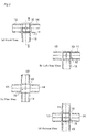
- connection parts envisioned for the framework of a typical box-shaped structure, such as 1) a connection part for connecting two paper tubes in a linear fashion, 2) a connection part for connecting two paper tubes at a right angle, 3) a connection part for connecting three paper tubes to form a T shape, 4) a connection part for connecting three paper tubes to be perpendicular to one another, 5) a connection part for connecting four paper tubes to form a cross shape, and 6) a connection part for connecting five paper tubes by adding one paper tube perpendicularly to the paper tubes formed in a cross shape.
- this paper tube connection device includes one or two or more paper tube connectors 1 formed by a resin (for example, an ABS resin).
- Each of the paper tube connectors 1 includes a base 10 having a regular hexahedron shape (a cuboidal shape), five male protrusions (in this example, square protrusions each having a square annular shape in a sectional shape) 11 to 15 that protrude from five respective faces among six faces of the base 10 and are to be inserted and press-fitted into respective center holes (in this example, center holes each having a square shape in a sectional shape) 21 of target paper tubes (in this example, square paper tubes each having a square annular shape in a sectional shape) 2, and a female recess 16 that opens at one face without any male protrusion 11 to 15 among the six faces of the base 10, and receives a similar male protrusion of another paper tube connector to be press-fitted thereto.
- all the lengths of the five male protrusions 11 to 15 are equal
- Such a configuration enables establishment of a direct connection between the paper tube connectors through press-fitting between one of the male protrusions 11 to 15 of the paper tube connector 1 and the female recess 16 of another paper tube connector 1 having any shape. Therefore, even in combination with any basic structure (the other paper tube connector 1 may be of a linear connection of two paper tubes, a right-angle connection of two paper tubes, a right-angle connection of three paper tubes, a cross-shaped connection of four paper tubes, or the like) of the paper tube connector itself, the design flexibility can be improved in designing the framework of the structure using the paper tubes.
- Figure 2 and Figure 3 each are a diagram illustrating a structure of the paper tube connector 1 with excellent design and high precision.
- Figure 2 is a projection diagram of the paper tube connector, excluding a rear view (the same as a front view) and a right side view (the same as a left side view).
- Figure 3(A) is a sectional view taken along line III-III of Figure 2(A)
- Figures 3(B) and 3(C) are perspective views from a top side and a bottom surface side, respectively.
- each of the male protrusions 11 to 15 is formed in a tapered shape, and three ridges a1, a2, and a3 are formed along an insertion direction on each of four outer peripheral side surfaces of the male protrusion (see Figure 1(A) ).
- the female recess 16 has an almost constant diameter in the depth direction, and two ridges b1 and b2 are formed along the insertion direction on each of four inner peripheral side surfaces of the female recess (see Figure 1(A) ).
- the ridges a1 to a3 and the ridges b1 and b2 have substantially the same height, and are alternately arranged with respect to one another so that the ridges do not interfere with one another when the male protrusion is press-fitted into the female recess.
- FIG. 4 An interior cabin (used as, for example, a playing house for kids, a private room for adults, a private room at a shelter at the time of disaster, or the like) 4 built using the above-described eight paper tube connectors 1 is illustrated in Figure 4 .
- a framework formed in a rectangular parallelepiped shape is built by connecting the paper tube connectors arranged at eight respective vertexes of the rectangular parallelepiped using the paper tubes 2, and corrugated cardboard plate materials 3 are bonded as left and right side wall plates 31 and 31, a front wall plate 32, and a rear wall plate (not illustrated) to the framework using a suitable adhesive or glue, whereby the interior cabin 4 is formed.
- the front wall plate 32 has an entrance door 32a formed by cutting out and hinge processing the corrugated cardboard plate material 3.
- the material of the wall plate is not limited to the corrugated cardboard plate material, and various boards such as a compressed board, or a resin board may be used as the material of the wall plate.
- FIG. 5 An example of a framework structure in which a plurality of the above-described paper tube connectors 1 are directly connected in one direction (series connection) is illustrated in Figure 5 .
- the plurality of paper tube connectors 1 having the same structure are connected by press-fitting the respective male protrusions 15 into the corresponding female recesses 16 to form a columnar connection body connected in series, and the two columnar connection bodies are arranged in a pair on left and right sides.
- a plurality of paper tubes 2, 2, .... are connected in parallel with one another between the two columnar connection bodies, to thereby form a hard wall body comprised of the parallel paper tubes.
- the paper tube connection device may also include various attachments described below.
- the attachment is provided with a male protrusion to be press-fitted into the female recess 16 of the paper tube connector 1 and a function achieving part that achieves a predetermined function.
- an attachment 5 includes a blind plate 51 and a male protrusion 52 provided on one face side of the blind plate 51.
- Three ridges a1, a2, and a3 are formed on each of four outer peripheral side surfaces of the male protrusion 52, as described above.
- the male protrusion 52 is press-fitted into the female recess 16 of the paper tube connector 1 as illustrated in Figure 6(A) to cover an opening of the female recess 16 of the paper tube connector 1 with the blind plate 51 as illustrated in Figure 6(B) , whereby the appearance can be improved.
- an attachment 6 includes a flange 61, a male protrusion 62 provided on one face side of the flange 61, and an additional male protrusion 63 provided on the other surface side of the flange 61.
- Three ridges a1, a2, and a3 are formed on each of four outer peripheral side surfaces of each of the male protrusions 62 and 63, as described above.
- the male protrusion 62 is press-fitted into the female recess 16 of the paper tube connector 1 as illustrated in Figure 7(A) and one-directional male protrusion 63 is further added to the five-directional paper tube connector 1, thereby achieving a six-directional paper tube connector as illustrated in Figure 7(B) .
- an attachment 7 includes a hinge portion 71, a male protrusion 72 provided on a first pivot plate 71b included in the hinge portion 71, and a male protrusion 73 provided on a second pivot plate 71a included in the hinge portion 71.
- Three ridges a1, a2, and a3 are formed on each of four outer peripheral side surfaces of each of the male protrusions 72 and 73, as described above.
- the detail of the hinge portion 71 is illustrated in Figure 9(A) .
- the hinge portion 71 includes the first pivot plate 71b having a pin passing portion protruding from one side edge thereof, the second pivot plate 71a having a pin passing portion protruding from one side edge thereof, and a hinge pin 71c passing through the above-described pin passing portions.
- the male protrusion 72 is press-fitted into the female recess 16 of the paper tube connector 1 as illustrated in Figure 9(A) , so that the hinged male protrusion 73 for connecting the paper tube 2 can be added to the five-directional paper tube connector 1.
- the hinged paper tube connector 1A can be attached to an inclined lower end of the paper tube 2A serving as a rafter of a roof, for example, as illustrated in Figures 10(A) and 10(B) , thereby forming an interior cabin 8 having a roof inclined at an arbitrary inclined angle, or the hinged paper tube connector 1A can be attached to a side edge of a paper tube type rectangular frame serving as a hinged door (not illustrated), thereby easily forming a pivotable hinged door.
- the gist of the present invention is defined by the description of the scope of the claims.
- the configuration of the base is not limited to a regular hexahedron, and it is needless to say that the present invention can be widely applied to the paper tube connector including a base having a polyhedron shape such as a regular tetrahedron shape and a regular octahedron shape.
- the number of male protrusions may be any of two (linear connection, right-angle connection), three (connection with 90 degree angle difference from one another), and four (a cross-shaped connection).
- each cross section of the male protrusion, the female recess, and the paper tube is formed in a square shape, but in the paper tube connector of the present invention, the cross section of them may be formed in other regular polygonal shape or a circular shape.
- all the lengths of the five male protrusions 11 to 15 are equal, but in the paper tube connector of the present invention, the lengths of the male protrusions may be different as shown in an example in which only one of the plurality of male protrusions is longer than the other male protrusions having the same length.
- the present invention can be utilized in an industry of manufacturing a paper tube connector using a resin molding technique.
Landscapes
- Engineering & Computer Science (AREA)
- General Engineering & Computer Science (AREA)
- Mechanical Engineering (AREA)
- Mutual Connection Of Rods And Tubes (AREA)
- Joining Of Building Structures In Genera (AREA)
- Finishing Walls (AREA)
- Storage Of Web-Like Or Filamentary Materials (AREA)
Applications Claiming Priority (2)
| Application Number | Priority Date | Filing Date | Title |
|---|---|---|---|
| JP2018077985A JP6943439B2 (ja) | 2018-04-13 | 2018-04-13 | 紙管の連結装置 |
| PCT/JP2019/015306 WO2019198660A1 (fr) | 2018-04-13 | 2019-04-08 | Dispositif de raccordement de tubes en papier |
Publications (4)
| Publication Number | Publication Date |
|---|---|
| EP3779214A1 true EP3779214A1 (fr) | 2021-02-17 |
| EP3779214A4 EP3779214A4 (fr) | 2022-01-05 |
| EP3779214C0 EP3779214C0 (fr) | 2024-01-24 |
| EP3779214B1 EP3779214B1 (fr) | 2024-01-24 |
Family
ID=68163122
Family Applications (1)
| Application Number | Title | Priority Date | Filing Date |
|---|---|---|---|
| EP19786163.6A Active EP3779214B1 (fr) | 2018-04-13 | 2019-04-08 | Dispositif de raccordement de tubes en papier |
Country Status (3)
| Country | Link |
|---|---|
| EP (1) | EP3779214B1 (fr) |
| JP (1) | JP6943439B2 (fr) |
| WO (1) | WO2019198660A1 (fr) |
Cited By (1)
| Publication number | Priority date | Publication date | Assignee | Title |
|---|---|---|---|---|
| WO2025224444A1 (fr) * | 2024-04-26 | 2025-10-30 | Mccreadie Rowland Timothy | Élément de jonction de cadre modulaire et système de cadre le comprenant |
Families Citing this family (6)
| Publication number | Priority date | Publication date | Assignee | Title |
|---|---|---|---|---|
| CN111734173A (zh) * | 2020-07-01 | 2020-10-02 | 广州番禺职业技术学院 | 一种可循环使用的自助搭建展示厅 |
| CN112483518A (zh) * | 2020-11-16 | 2021-03-12 | 广州海方科技股份有限公司 | 一种纸管连接接头 |
| DE202020106774U1 (de) * | 2020-11-25 | 2020-12-07 | Häfele GmbH & Co KG | Eckverbinder sowie Rahmen und Klappbett mit solch einem Eckverbinder |
| KR102307901B1 (ko) * | 2021-05-10 | 2021-10-05 | 스타우스 주식회사 | 코너캐스터를 적용한 철골 모듈러 장치 |
| US11828444B1 (en) * | 2022-09-30 | 2023-11-28 | Energy Light, Inc. | Modular light pole assembly and method of assembling a modular light pole |
| GB2627792B (en) * | 2023-03-02 | 2026-03-18 | Ocado Innovation Ltd | Grid Framework Structure |
Family Cites Families (12)
| Publication number | Priority date | Publication date | Assignee | Title |
|---|---|---|---|---|
| GB1313299A (en) * | 1969-07-01 | 1973-04-11 | Link 51 Ltd | Spigot devices to engage sockets of framework members |
| JPS5212582Y2 (fr) * | 1973-03-07 | 1977-03-19 | ||
| JPS5631708B2 (fr) * | 1974-02-02 | 1981-07-23 | ||
| JPS5813131Y2 (ja) * | 1979-12-11 | 1983-03-14 | 杉浦 武 | 棚、建具等の構成用パネルと接合用ジョイントの組合せ |
| JPS5768004U (fr) * | 1980-10-09 | 1982-04-23 | ||
| JPH0724396U (ja) * | 1991-08-23 | 1995-05-09 | ピープル株式会社 | 伸縮自在な滑り台 |
| JPH0746280Y2 (ja) * | 1992-09-03 | 1995-10-25 | 美倍紙業株式会社 | 室内用ジャングルジム |
| CZ606U1 (cs) * | 1993-04-22 | 1993-08-25 | Josef Ing. Javorka | Modulový konstrukční prvek lehké stavební jednotky |
| JPH0739604A (ja) * | 1993-08-02 | 1995-02-10 | P-Puru Kk | 組み立て型ジャングルジムのパイプコネクタ |
| JP2006204776A (ja) * | 2005-01-31 | 2006-08-10 | Staff:Kk | ジャングルジム用継手 |
| ES2631007T3 (es) * | 2013-09-25 | 2017-08-25 | Toni Zamora Masnou | Módulo de almacenamiento y transporte para piezas en línea de montaje |
| JP2017210993A (ja) | 2016-05-24 | 2017-11-30 | 日本化工機材株式会社 | 接続部材および棚 |
-
2018
- 2018-04-13 JP JP2018077985A patent/JP6943439B2/ja active Active
-
2019
- 2019-04-08 WO PCT/JP2019/015306 patent/WO2019198660A1/fr not_active Ceased
- 2019-04-08 EP EP19786163.6A patent/EP3779214B1/fr active Active
Cited By (1)
| Publication number | Priority date | Publication date | Assignee | Title |
|---|---|---|---|---|
| WO2025224444A1 (fr) * | 2024-04-26 | 2025-10-30 | Mccreadie Rowland Timothy | Élément de jonction de cadre modulaire et système de cadre le comprenant |
Also Published As
| Publication number | Publication date |
|---|---|
| WO2019198660A1 (fr) | 2019-10-17 |
| EP3779214C0 (fr) | 2024-01-24 |
| JP6943439B2 (ja) | 2021-09-29 |
| JP2019184009A (ja) | 2019-10-24 |
| EP3779214B1 (fr) | 2024-01-24 |
| EP3779214A4 (fr) | 2022-01-05 |
Similar Documents
| Publication | Publication Date | Title |
|---|---|---|
| EP3779214B1 (fr) | Dispositif de raccordement de tubes en papier | |
| US3992839A (en) | Snap-on paneling | |
| JP3221637B2 (ja) | 組立てブロック | |
| US7347028B1 (en) | Modular construction system utilizing versatile construction elements with multi-directional connective surfaces and releasable interconnect elements | |
| US10617968B2 (en) | Building blocks | |
| US6558222B1 (en) | Panelling and supports for interconnected toy blocks | |
| EP1501617B1 (fr) | Element a verrouillage reciproque pour ensemble structural | |
| US11110368B2 (en) | Structural element | |
| US5152710A (en) | Fold open play set with slotted base | |
| US3973855A (en) | Connecting device for panels and tubes | |
| US8628089B2 (en) | Jigsaw puzzle having one or more puzzle pieces that can be bent | |
| US20070077854A1 (en) | Sectional three-dimensional model | |
| CA2838286A1 (fr) | Systeme de meuble modulaire et meuble modulaire | |
| KR102094641B1 (ko) | 6-웨이 커넥터모듈 | |
| TWI595848B (zh) | Diaphragm connection block and partition | |
| US20190192987A1 (en) | Toy building brick system | |
| KR20170065212A (ko) | 탄성벽을 이용한 체결구조를 가지는 디오라마 조립식 블록 | |
| JP6675710B2 (ja) | 板材連結機構、区画室及び機構連結方法 | |
| KR101968053B1 (ko) | 사각 기둥부재용 커넥터 모듈 | |
| WO2023031703A1 (fr) | Composant de brique magnétique | |
| JP5995446B2 (ja) | 組み立て式展示台 | |
| CN211912729U (zh) | 组合组件 | |
| JP3181728U (ja) | 組み合わせ式組み立てブロック | |
| EP3363515A1 (fr) | Système de construction | |
| KR20170028770A (ko) | 탄성체로 이루어진 체결구를 갖는 조립식 블록 |
Legal Events
| Date | Code | Title | Description |
|---|---|---|---|
| STAA | Information on the status of an ep patent application or granted ep patent |
Free format text: STATUS: THE INTERNATIONAL PUBLICATION HAS BEEN MADE |
|
| PUAI | Public reference made under article 153(3) epc to a published international application that has entered the european phase |
Free format text: ORIGINAL CODE: 0009012 |
|
| STAA | Information on the status of an ep patent application or granted ep patent |
Free format text: STATUS: REQUEST FOR EXAMINATION WAS MADE |
|
| 17P | Request for examination filed |
Effective date: 20201103 |
|
| AK | Designated contracting states |
Kind code of ref document: A1 Designated state(s): AL AT BE BG CH CY CZ DE DK EE ES FI FR GB GR HR HU IE IS IT LI LT LU LV MC MK MT NL NO PL PT RO RS SE SI SK SM TR |
|
| AX | Request for extension of the european patent |
Extension state: BA ME |
|
| DAV | Request for validation of the european patent (deleted) | ||
| DAX | Request for extension of the european patent (deleted) | ||
| A4 | Supplementary search report drawn up and despatched |
Effective date: 20211207 |
|
| RIC1 | Information provided on ipc code assigned before grant |
Ipc: F16B 4/00 20060101ALI20211201BHEP Ipc: E04H 1/12 20060101ALI20211201BHEP Ipc: E04B 1/58 20060101ALI20211201BHEP Ipc: A63B 17/00 20060101ALI20211201BHEP Ipc: F16B 7/04 20060101ALI20211201BHEP Ipc: F16B 7/20 20060101AFI20211201BHEP |
|
| RIN1 | Information on inventor provided before grant (corrected) |
Inventor name: WATANABE, KAZUTOSHI |
|
| GRAP | Despatch of communication of intention to grant a patent |
Free format text: ORIGINAL CODE: EPIDOSNIGR1 |
|
| STAA | Information on the status of an ep patent application or granted ep patent |
Free format text: STATUS: GRANT OF PATENT IS INTENDED |
|
| INTG | Intention to grant announced |
Effective date: 20230809 |
|
| GRAS | Grant fee paid |
Free format text: ORIGINAL CODE: EPIDOSNIGR3 |
|
| GRAA | (expected) grant |
Free format text: ORIGINAL CODE: 0009210 |
|
| STAA | Information on the status of an ep patent application or granted ep patent |
Free format text: STATUS: THE PATENT HAS BEEN GRANTED |
|
| AK | Designated contracting states |
Kind code of ref document: B1 Designated state(s): AL AT BE BG CH CY CZ DE DK EE ES FI FR GB GR HR HU IE IS IT LI LT LU LV MC MK MT NL NO PL PT RO RS SE SI SK SM TR |
|
| REG | Reference to a national code |
Ref country code: GB Ref legal event code: FG4D |
|
| REG | Reference to a national code |
Ref country code: CH Ref legal event code: EP |
|
| REG | Reference to a national code |
Ref country code: IE Ref legal event code: FG4D |
|
| REG | Reference to a national code |
Ref country code: DE Ref legal event code: R096 Ref document number: 602019045652 Country of ref document: DE |
|
| U01 | Request for unitary effect filed |
Effective date: 20240221 |
|
| U07 | Unitary effect registered |
Designated state(s): AT BE BG DE DK EE FI FR IT LT LU LV MT NL PT SE SI Effective date: 20240229 |
|
| REG | Reference to a national code |
Ref country code: LT Ref legal event code: MG9D |
|
| U20 | Renewal fee for the european patent with unitary effect paid |
Year of fee payment: 6 Effective date: 20240429 |
|
| PG25 | Lapsed in a contracting state [announced via postgrant information from national office to epo] |
Ref country code: IS Free format text: LAPSE BECAUSE OF FAILURE TO SUBMIT A TRANSLATION OF THE DESCRIPTION OR TO PAY THE FEE WITHIN THE PRESCRIBED TIME-LIMIT Effective date: 20240524 |
|
| PG25 | Lapsed in a contracting state [announced via postgrant information from national office to epo] |
Ref country code: GR Free format text: LAPSE BECAUSE OF FAILURE TO SUBMIT A TRANSLATION OF THE DESCRIPTION OR TO PAY THE FEE WITHIN THE PRESCRIBED TIME-LIMIT Effective date: 20240425 |
|
| PG25 | Lapsed in a contracting state [announced via postgrant information from national office to epo] |
Ref country code: RS Free format text: LAPSE BECAUSE OF FAILURE TO SUBMIT A TRANSLATION OF THE DESCRIPTION OR TO PAY THE FEE WITHIN THE PRESCRIBED TIME-LIMIT Effective date: 20240424 Ref country code: HR Free format text: LAPSE BECAUSE OF FAILURE TO SUBMIT A TRANSLATION OF THE DESCRIPTION OR TO PAY THE FEE WITHIN THE PRESCRIBED TIME-LIMIT Effective date: 20240124 |
|
| PG25 | Lapsed in a contracting state [announced via postgrant information from national office to epo] |
Ref country code: ES Free format text: LAPSE BECAUSE OF FAILURE TO SUBMIT A TRANSLATION OF THE DESCRIPTION OR TO PAY THE FEE WITHIN THE PRESCRIBED TIME-LIMIT Effective date: 20240124 |
|
| PG25 | Lapsed in a contracting state [announced via postgrant information from national office to epo] |
Ref country code: RS Free format text: LAPSE BECAUSE OF FAILURE TO SUBMIT A TRANSLATION OF THE DESCRIPTION OR TO PAY THE FEE WITHIN THE PRESCRIBED TIME-LIMIT Effective date: 20240424 Ref country code: NO Free format text: LAPSE BECAUSE OF FAILURE TO SUBMIT A TRANSLATION OF THE DESCRIPTION OR TO PAY THE FEE WITHIN THE PRESCRIBED TIME-LIMIT Effective date: 20240424 Ref country code: IS Free format text: LAPSE BECAUSE OF FAILURE TO SUBMIT A TRANSLATION OF THE DESCRIPTION OR TO PAY THE FEE WITHIN THE PRESCRIBED TIME-LIMIT Effective date: 20240524 Ref country code: HR Free format text: LAPSE BECAUSE OF FAILURE TO SUBMIT A TRANSLATION OF THE DESCRIPTION OR TO PAY THE FEE WITHIN THE PRESCRIBED TIME-LIMIT Effective date: 20240124 Ref country code: GR Free format text: LAPSE BECAUSE OF FAILURE TO SUBMIT A TRANSLATION OF THE DESCRIPTION OR TO PAY THE FEE WITHIN THE PRESCRIBED TIME-LIMIT Effective date: 20240425 Ref country code: ES Free format text: LAPSE BECAUSE OF FAILURE TO SUBMIT A TRANSLATION OF THE DESCRIPTION OR TO PAY THE FEE WITHIN THE PRESCRIBED TIME-LIMIT Effective date: 20240124 |
|
| PG25 | Lapsed in a contracting state [announced via postgrant information from national office to epo] |
Ref country code: PL Free format text: LAPSE BECAUSE OF FAILURE TO SUBMIT A TRANSLATION OF THE DESCRIPTION OR TO PAY THE FEE WITHIN THE PRESCRIBED TIME-LIMIT Effective date: 20240124 |
|
| PG25 | Lapsed in a contracting state [announced via postgrant information from national office to epo] |
Ref country code: PL Free format text: LAPSE BECAUSE OF FAILURE TO SUBMIT A TRANSLATION OF THE DESCRIPTION OR TO PAY THE FEE WITHIN THE PRESCRIBED TIME-LIMIT Effective date: 20240124 |
|
| PG25 | Lapsed in a contracting state [announced via postgrant information from national office to epo] |
Ref country code: SM Free format text: LAPSE BECAUSE OF FAILURE TO SUBMIT A TRANSLATION OF THE DESCRIPTION OR TO PAY THE FEE WITHIN THE PRESCRIBED TIME-LIMIT Effective date: 20240124 |
|
| PG25 | Lapsed in a contracting state [announced via postgrant information from national office to epo] |
Ref country code: CZ Free format text: LAPSE BECAUSE OF FAILURE TO SUBMIT A TRANSLATION OF THE DESCRIPTION OR TO PAY THE FEE WITHIN THE PRESCRIBED TIME-LIMIT Effective date: 20240124 |
|
| REG | Reference to a national code |
Ref country code: DE Ref legal event code: R097 Ref document number: 602019045652 Country of ref document: DE |
|
| PG25 | Lapsed in a contracting state [announced via postgrant information from national office to epo] |
Ref country code: SK Free format text: LAPSE BECAUSE OF FAILURE TO SUBMIT A TRANSLATION OF THE DESCRIPTION OR TO PAY THE FEE WITHIN THE PRESCRIBED TIME-LIMIT Effective date: 20240124 |
|
| PG25 | Lapsed in a contracting state [announced via postgrant information from national office to epo] |
Ref country code: SM Free format text: LAPSE BECAUSE OF FAILURE TO SUBMIT A TRANSLATION OF THE DESCRIPTION OR TO PAY THE FEE WITHIN THE PRESCRIBED TIME-LIMIT Effective date: 20240124 Ref country code: SK Free format text: LAPSE BECAUSE OF FAILURE TO SUBMIT A TRANSLATION OF THE DESCRIPTION OR TO PAY THE FEE WITHIN THE PRESCRIBED TIME-LIMIT Effective date: 20240124 Ref country code: CZ Free format text: LAPSE BECAUSE OF FAILURE TO SUBMIT A TRANSLATION OF THE DESCRIPTION OR TO PAY THE FEE WITHIN THE PRESCRIBED TIME-LIMIT Effective date: 20240124 |
|
| PG25 | Lapsed in a contracting state [announced via postgrant information from national office to epo] |
Ref country code: MC Free format text: LAPSE BECAUSE OF FAILURE TO SUBMIT A TRANSLATION OF THE DESCRIPTION OR TO PAY THE FEE WITHIN THE PRESCRIBED TIME-LIMIT Effective date: 20240124 |
|
| PG25 | Lapsed in a contracting state [announced via postgrant information from national office to epo] |
Ref country code: MC Free format text: LAPSE BECAUSE OF FAILURE TO SUBMIT A TRANSLATION OF THE DESCRIPTION OR TO PAY THE FEE WITHIN THE PRESCRIBED TIME-LIMIT Effective date: 20240124 |
|
| PLBE | No opposition filed within time limit |
Free format text: ORIGINAL CODE: 0009261 |
|
| REG | Reference to a national code |
Ref country code: CH Ref legal event code: PL |
|
| STAA | Information on the status of an ep patent application or granted ep patent |
Free format text: STATUS: NO OPPOSITION FILED WITHIN TIME LIMIT |
|
| GBPC | Gb: european patent ceased through non-payment of renewal fee |
Effective date: 20240424 |
|
| 26N | No opposition filed |
Effective date: 20241025 |
|
| PG25 | Lapsed in a contracting state [announced via postgrant information from national office to epo] |
Ref country code: GB Free format text: LAPSE BECAUSE OF NON-PAYMENT OF DUE FEES Effective date: 20240424 |
|
| PG25 | Lapsed in a contracting state [announced via postgrant information from national office to epo] |
Ref country code: GB Free format text: LAPSE BECAUSE OF NON-PAYMENT OF DUE FEES Effective date: 20240424 Ref country code: CH Free format text: LAPSE BECAUSE OF NON-PAYMENT OF DUE FEES Effective date: 20240430 |
|
| PG25 | Lapsed in a contracting state [announced via postgrant information from national office to epo] |
Ref country code: IE Free format text: LAPSE BECAUSE OF NON-PAYMENT OF DUE FEES Effective date: 20240408 |
|
| U20 | Renewal fee for the european patent with unitary effect paid |
Year of fee payment: 7 Effective date: 20250429 |
|
| PG25 | Lapsed in a contracting state [announced via postgrant information from national office to epo] |
Ref country code: RO Free format text: LAPSE BECAUSE OF FAILURE TO SUBMIT A TRANSLATION OF THE DESCRIPTION OR TO PAY THE FEE WITHIN THE PRESCRIBED TIME-LIMIT Effective date: 20240124 |
|
| PG25 | Lapsed in a contracting state [announced via postgrant information from national office to epo] |
Ref country code: CY Free format text: LAPSE BECAUSE OF FAILURE TO SUBMIT A TRANSLATION OF THE DESCRIPTION OR TO PAY THE FEE WITHIN THE PRESCRIBED TIME-LIMIT; INVALID AB INITIO Effective date: 20190408 |
|
| PG25 | Lapsed in a contracting state [announced via postgrant information from national office to epo] |
Ref country code: HU Free format text: LAPSE BECAUSE OF FAILURE TO SUBMIT A TRANSLATION OF THE DESCRIPTION OR TO PAY THE FEE WITHIN THE PRESCRIBED TIME-LIMIT; INVALID AB INITIO Effective date: 20190408 |