EP3779237A1 - Transmission différentielle - Google Patents
Transmission différentielle Download PDFInfo
- Publication number
- EP3779237A1 EP3779237A1 EP19785465.6A EP19785465A EP3779237A1 EP 3779237 A1 EP3779237 A1 EP 3779237A1 EP 19785465 A EP19785465 A EP 19785465A EP 3779237 A1 EP3779237 A1 EP 3779237A1
- Authority
- EP
- European Patent Office
- Prior art keywords
- speed shaft
- speed
- gear type
- main body
- pin
- Prior art date
- Legal status (The legal status is an assumption and is not a legal conclusion. Google has not performed a legal analysis and makes no representation as to the accuracy of the status listed.)
- Ceased
Links
- 230000005540 biological transmission Effects 0.000 title claims abstract description 60
- 239000000314 lubricant Substances 0.000 description 15
- 230000001133 acceleration Effects 0.000 description 6
- 238000012905 input function Methods 0.000 description 2
- 238000005461 lubrication Methods 0.000 description 2
- 239000004065 semiconductor Substances 0.000 description 2
- 238000005299 abrasion Methods 0.000 description 1
- 239000003638 chemical reducing agent Substances 0.000 description 1
- 230000000694 effects Effects 0.000 description 1
- 230000020169 heat generation Effects 0.000 description 1
- 238000004519 manufacturing process Methods 0.000 description 1
- 238000000034 method Methods 0.000 description 1
- 238000005096 rolling process Methods 0.000 description 1
- 238000007665 sagging Methods 0.000 description 1
Images






Classifications
-
- F—MECHANICAL ENGINEERING; LIGHTING; HEATING; WEAPONS; BLASTING
- F16—ENGINEERING ELEMENTS AND UNITS; GENERAL MEASURES FOR PRODUCING AND MAINTAINING EFFECTIVE FUNCTIONING OF MACHINES OR INSTALLATIONS; THERMAL INSULATION IN GENERAL
- F16H—GEARING
- F16H1/00—Toothed gearings for conveying rotary motion
- F16H1/28—Toothed gearings for conveying rotary motion with gears having orbital motion
- F16H1/32—Toothed gearings for conveying rotary motion with gears having orbital motion in which the central axis of the gearing lies inside the periphery of an orbital gear
-
- F—MECHANICAL ENGINEERING; LIGHTING; HEATING; WEAPONS; BLASTING
- F16—ENGINEERING ELEMENTS AND UNITS; GENERAL MEASURES FOR PRODUCING AND MAINTAINING EFFECTIVE FUNCTIONING OF MACHINES OR INSTALLATIONS; THERMAL INSULATION IN GENERAL
- F16H—GEARING
- F16H3/00—Toothed gearings for conveying rotary motion with variable gear ratio or for reversing rotary motion
- F16H3/44—Toothed gearings for conveying rotary motion with variable gear ratio or for reversing rotary motion using gears having orbital motion
- F16H3/72—Toothed gearings for conveying rotary motion with variable gear ratio or for reversing rotary motion using gears having orbital motion with a secondary drive, e.g. regulating motor, in order to vary speed continuously
-
- F—MECHANICAL ENGINEERING; LIGHTING; HEATING; WEAPONS; BLASTING
- F16—ENGINEERING ELEMENTS AND UNITS; GENERAL MEASURES FOR PRODUCING AND MAINTAINING EFFECTIVE FUNCTIONING OF MACHINES OR INSTALLATIONS; THERMAL INSULATION IN GENERAL
- F16C—SHAFTS; FLEXIBLE SHAFTS; ELEMENTS OR CRANKSHAFT MECHANISMS; ROTARY BODIES OTHER THAN GEARING ELEMENTS; BEARINGS
- F16C3/00—Shafts; Axles; Cranks; Eccentrics
- F16C3/02—Shafts; Axles
-
- F—MECHANICAL ENGINEERING; LIGHTING; HEATING; WEAPONS; BLASTING
- F16—ENGINEERING ELEMENTS AND UNITS; GENERAL MEASURES FOR PRODUCING AND MAINTAINING EFFECTIVE FUNCTIONING OF MACHINES OR INSTALLATIONS; THERMAL INSULATION IN GENERAL
- F16H—GEARING
- F16H1/00—Toothed gearings for conveying rotary motion
- F16H1/28—Toothed gearings for conveying rotary motion with gears having orbital motion
- F16H1/34—Toothed gearings for conveying rotary motion with gears having orbital motion involving gears essentially having intermeshing elements other than involute or cycloidal teeth
-
- F—MECHANICAL ENGINEERING; LIGHTING; HEATING; WEAPONS; BLASTING
- F16—ENGINEERING ELEMENTS AND UNITS; GENERAL MEASURES FOR PRODUCING AND MAINTAINING EFFECTIVE FUNCTIONING OF MACHINES OR INSTALLATIONS; THERMAL INSULATION IN GENERAL
- F16C—SHAFTS; FLEXIBLE SHAFTS; ELEMENTS OR CRANKSHAFT MECHANISMS; ROTARY BODIES OTHER THAN GEARING ELEMENTS; BEARINGS
- F16C2300/00—Application independent of particular apparatuses
-
- F—MECHANICAL ENGINEERING; LIGHTING; HEATING; WEAPONS; BLASTING
- F16—ENGINEERING ELEMENTS AND UNITS; GENERAL MEASURES FOR PRODUCING AND MAINTAINING EFFECTIVE FUNCTIONING OF MACHINES OR INSTALLATIONS; THERMAL INSULATION IN GENERAL
- F16C—SHAFTS; FLEXIBLE SHAFTS; ELEMENTS OR CRANKSHAFT MECHANISMS; ROTARY BODIES OTHER THAN GEARING ELEMENTS; BEARINGS
- F16C2300/00—Application independent of particular apparatuses
- F16C2300/02—General use or purpose, i.e. no use, purpose, special adaptation or modification indicated or a wide variety of uses mentioned
-
- F—MECHANICAL ENGINEERING; LIGHTING; HEATING; WEAPONS; BLASTING
- F16—ENGINEERING ELEMENTS AND UNITS; GENERAL MEASURES FOR PRODUCING AND MAINTAINING EFFECTIVE FUNCTIONING OF MACHINES OR INSTALLATIONS; THERMAL INSULATION IN GENERAL
- F16C—SHAFTS; FLEXIBLE SHAFTS; ELEMENTS OR CRANKSHAFT MECHANISMS; ROTARY BODIES OTHER THAN GEARING ELEMENTS; BEARINGS
- F16C2300/00—Application independent of particular apparatuses
- F16C2300/20—Application independent of particular apparatuses related to type of movement
- F16C2300/22—High-speed rotation
-
- F—MECHANICAL ENGINEERING; LIGHTING; HEATING; WEAPONS; BLASTING
- F16—ENGINEERING ELEMENTS AND UNITS; GENERAL MEASURES FOR PRODUCING AND MAINTAINING EFFECTIVE FUNCTIONING OF MACHINES OR INSTALLATIONS; THERMAL INSULATION IN GENERAL
- F16C—SHAFTS; FLEXIBLE SHAFTS; ELEMENTS OR CRANKSHAFT MECHANISMS; ROTARY BODIES OTHER THAN GEARING ELEMENTS; BEARINGS
- F16C2361/00—Apparatus or articles in engineering in general
- F16C2361/61—Toothed gear systems, e.g. support of pinion shafts
-
- F—MECHANICAL ENGINEERING; LIGHTING; HEATING; WEAPONS; BLASTING
- F16—ENGINEERING ELEMENTS AND UNITS; GENERAL MEASURES FOR PRODUCING AND MAINTAINING EFFECTIVE FUNCTIONING OF MACHINES OR INSTALLATIONS; THERMAL INSULATION IN GENERAL
- F16H—GEARING
- F16H1/00—Toothed gearings for conveying rotary motion
- F16H1/02—Toothed gearings for conveying rotary motion without gears having orbital motion
- F16H1/24—Toothed gearings for conveying rotary motion without gears having orbital motion involving gears essentially having intermeshing elements other than involute or cycloidal teeth
-
- F—MECHANICAL ENGINEERING; LIGHTING; HEATING; WEAPONS; BLASTING
- F16—ENGINEERING ELEMENTS AND UNITS; GENERAL MEASURES FOR PRODUCING AND MAINTAINING EFFECTIVE FUNCTIONING OF MACHINES OR INSTALLATIONS; THERMAL INSULATION IN GENERAL
- F16H—GEARING
- F16H19/00—Gearings comprising essentially only toothed gears or friction members and not capable of conveying indefinitely-continuing rotary motion
- F16H19/02—Gearings comprising essentially only toothed gears or friction members and not capable of conveying indefinitely-continuing rotary motion for interconverting rotary or oscillating motion and reciprocating motion
- F16H19/04—Gearings comprising essentially only toothed gears or friction members and not capable of conveying indefinitely-continuing rotary motion for interconverting rotary or oscillating motion and reciprocating motion comprising a rack
-
- F—MECHANICAL ENGINEERING; LIGHTING; HEATING; WEAPONS; BLASTING
- F16—ENGINEERING ELEMENTS AND UNITS; GENERAL MEASURES FOR PRODUCING AND MAINTAINING EFFECTIVE FUNCTIONING OF MACHINES OR INSTALLATIONS; THERMAL INSULATION IN GENERAL
- F16H—GEARING
- F16H1/00—Toothed gearings for conveying rotary motion
- F16H1/28—Toothed gearings for conveying rotary motion with gears having orbital motion
- F16H1/32—Toothed gearings for conveying rotary motion with gears having orbital motion in which the central axis of the gearing lies inside the periphery of an orbital gear
- F16H2001/325—Toothed gearings for conveying rotary motion with gears having orbital motion in which the central axis of the gearing lies inside the periphery of an orbital gear comprising a carrier with pins guiding at least one orbital gear with circular holes
-
- F—MECHANICAL ENGINEERING; LIGHTING; HEATING; WEAPONS; BLASTING
- F16—ENGINEERING ELEMENTS AND UNITS; GENERAL MEASURES FOR PRODUCING AND MAINTAINING EFFECTIVE FUNCTIONING OF MACHINES OR INSTALLATIONS; THERMAL INSULATION IN GENERAL
- F16H—GEARING
- F16H37/00—Combinations of mechanical gearings, not provided for in groups F16H1/00 - F16H35/00
- F16H37/02—Combinations of mechanical gearings, not provided for in groups F16H1/00 - F16H35/00 comprising essentially only toothed or friction gearings
- F16H37/04—Combinations of toothed gearings only
- F16H37/041—Combinations of toothed gearings only for conveying rotary motion with constant gear ratio
-
- F—MECHANICAL ENGINEERING; LIGHTING; HEATING; WEAPONS; BLASTING
- F16—ENGINEERING ELEMENTS AND UNITS; GENERAL MEASURES FOR PRODUCING AND MAINTAINING EFFECTIVE FUNCTIONING OF MACHINES OR INSTALLATIONS; THERMAL INSULATION IN GENERAL
- F16H—GEARING
- F16H55/00—Elements with teeth or friction surfaces for conveying motion; Worms, pulleys or sheaves for gearing mechanisms
- F16H55/02—Toothed members; Worms
- F16H55/10—Constructively simple tooth shapes, e.g. shaped as pins, as balls
-
- F—MECHANICAL ENGINEERING; LIGHTING; HEATING; WEAPONS; BLASTING
- F16—ENGINEERING ELEMENTS AND UNITS; GENERAL MEASURES FOR PRODUCING AND MAINTAINING EFFECTIVE FUNCTIONING OF MACHINES OR INSTALLATIONS; THERMAL INSULATION IN GENERAL
- F16H—GEARING
- F16H57/00—General details of gearing
- F16H57/04—Features relating to lubrication or cooling or heating
- F16H57/042—Guidance of lubricant
- F16H57/043—Guidance of lubricant within rotary parts, e.g. axial channels or radial openings in shafts
-
- F—MECHANICAL ENGINEERING; LIGHTING; HEATING; WEAPONS; BLASTING
- F16—ENGINEERING ELEMENTS AND UNITS; GENERAL MEASURES FOR PRODUCING AND MAINTAINING EFFECTIVE FUNCTIONING OF MACHINES OR INSTALLATIONS; THERMAL INSULATION IN GENERAL
- F16H—GEARING
- F16H57/00—General details of gearing
- F16H57/04—Features relating to lubrication or cooling or heating
- F16H57/042—Guidance of lubricant
- F16H57/043—Guidance of lubricant within rotary parts, e.g. axial channels or radial openings in shafts
- F16H57/0431—Means for guiding lubricant directly onto a tooth surface or to foot areas of a gear, e.g. by holes or grooves in a tooth flank
-
- F—MECHANICAL ENGINEERING; LIGHTING; HEATING; WEAPONS; BLASTING
- F16—ENGINEERING ELEMENTS AND UNITS; GENERAL MEASURES FOR PRODUCING AND MAINTAINING EFFECTIVE FUNCTIONING OF MACHINES OR INSTALLATIONS; THERMAL INSULATION IN GENERAL
- F16H—GEARING
- F16H57/00—General details of gearing
- F16H57/04—Features relating to lubrication or cooling or heating
- F16H57/048—Type of gearings to be lubricated, cooled or heated
-
- F—MECHANICAL ENGINEERING; LIGHTING; HEATING; WEAPONS; BLASTING
- F16—ENGINEERING ELEMENTS AND UNITS; GENERAL MEASURES FOR PRODUCING AND MAINTAINING EFFECTIVE FUNCTIONING OF MACHINES OR INSTALLATIONS; THERMAL INSULATION IN GENERAL
- F16H—GEARING
- F16H57/00—General details of gearing
- F16H57/04—Features relating to lubrication or cooling or heating
- F16H57/048—Type of gearings to be lubricated, cooled or heated
- F16H57/0493—Gearings with spur or bevel gears
- F16H57/0495—Gearings with spur or bevel gears with fixed gear ratio
Definitions
- the present inventive concept relates to a differential transmission, and more particularly, to a differential transmission which has a compact structure and may easily perform implementation of a high-precision differential speed.
- Differential transmissions refer to devices capable of reducing, accelerating, or differentiating the speed of an output according to input conditions.
- a typical differential transmission includes a reducer, e.g., a planetary gear, having input/output on a co-axial line, and implement an output of a differential speed with respect to two different inputs.
- the differential transmission may be used to implement a differential speed in compact equipment such as index of a display or semiconductor equipment or the like.
- the present inventive concept provides a differential transmission which has a compact structure and may easily perform implementation of a high-precision differential speed.
- the implementation of a high-precision differential speed may be easily performed with a compact structure.
- a differential transmission includes a pin-gear type main body unit which includes a pin-gear type main body housing in which input or output is performed through a plurality of pins, the plurality of pins being rotatably coupled in a circumferential direction of an outer circumferential surface thereof, a high-speed shaft provided at one side of the pin-gear type main body housing and through which input or output of a first speed that is a relatively high speed is performed, a low-speed shaft provided at the other side of the pin-gear type main body housing and through which input or output of a second speed that is less than the first speed is performed, and a reduction portion provided inside the pin-gear type main body housing and reducing an input speed; and a high-speed shaft connection unit connected to the high-speed shaft of the pin-gear type main body unit and through which input or output is performed through the high-speed shaft.
- the high-speed shaft connection unit may include a pin-gear type high-speed shaft connection unit in which a plurality of pins are rotatably coupled in the circumferential direction of the outer circumferential surface thereof.
- the high-speed shaft connection unit may include a spur-gear type high-speed shaft connection unit in which gear teeth having a circular shape are formed in the circumferential direction of the outer circumferential surface thereof.
- a curve of the gear teeth having a circular shape may form a cycloid curve or a trochoid curve.
- a differential transmission includes a spur-gear type main body unit which includes a spur-gear type main body housing in which input or output is performed through a plurality of gear teeth, the plurality of gear teeth being formed in a circumferential direction of an outer circumferential surface thereof, a high-speed shaft provided at one side of the spur-gear type main body housing and through which input or output of a first speed that is a relatively high speed is performed, a low-speed shaft provided at the other side of the spur-gear type main body housing and through which input or output of a second speed that is less than the first speed is performed, and a reduction portion provided inside the spur-gear type main body housing and reducing an input speed, and a high-speed shaft connection unit connected to the high-speed shaft of the spur-gear type main body unit and through which input or output is performed through the high-speed shaft.
- a curve of the gear teeth may form a cycloid curve or a trochoid curve.
- the high-speed shaft connection unit may include a pin-gear type high-speed shaft connection unit in which a plurality of pins are rotatably coupled in the circumferential direction of the outer circumferential surface thereof.
- the high-speed shaft connection unit may include a spur-gear type high-speed shaft connection unit in which gear teeth having a circular shape are formed in the circumferential direction of the outer circumferential surface thereof.
- a curve of the gear teeth having a circular shape may form a cycloid curve or a trochoid curve.
- the reduction portion may include a planetary-gear type planetary gear reduction portion.
- the high-speed shaft may be manufactured in a shaft shape to correspond to a high speed
- the low-speed shaft may be manufactured in a shaft shape to correspond to a relative speed by a high-speed rotation.
- the high-speed shaft may include a first high-speed shaft portion having one end portion connected to the reduction portion and the other end portion connected to the high-speed shaft connection unit, and a second high-speed shaft portion coaxially disposed with the first high-speed shaft portion and having one side connected to the first high-speed shaft portion and the other side connected to the reduction portion.
- the reduction portion may include a plurality of high-speed shaft support bearings disposed apart from each other in a length direction of the second high-speed shaft portion.
- the low-speed shaft may include a first low-speed shaft portion having one end portion connected to the reduction portion and the other end portion disposed to be exposed to the outside, and second and third low-speed shaft portions having one side connected to the first low-speed shaft portion and the other side connected to the reduction portion, the second and third low-speed shaft portions being separated into a plurality of pieces that are connected to one another.
- the reduction portion may further include a plurality of main bearings disposed apart from each other at sides of the second and third low-speed shaft portions.
- FIG. 1 is a use state view of a differential transmission according to a first embodiment of the present inventive concept
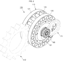
- FIG. 2 illustrates first and second dummy input/output units of FIG. 1 in a dashed line
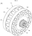
- FIG. 3 is an enlarged perspective view of a differential transmission
- FIG. 4 is a cross-sectional structural view of FIG. 3
- FIG. 5 is an enlarged view of major parts of FIG. 4
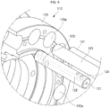
- FIG. 6 is a perspective view of major parts of a pin area.
- a differential transmission 100 may have a compact structure and easily perform implement of a high precision differential speed and include a pin-gear type main body unit 110 and a high-speed shaft connection unit 160.
- the pin-gear type main body unit 110 may mean a so-called pin gear (pin gear) in which a plurality of pins 121 are applied to an outer circumferential surface thereof.
- pin gear pin gear
- the pin-gear type main body unit 110 may include a pin-gear type main body housing 120, in which a reduction portion 150 is included, and a high-speed shaft 130 and a low-speed shaft 140, which are coupled to the pin-gear type main body housing 120.
- the high-speed shaft 130 (see FIG. 4 ) is provided at one side of the pin-gear type main body housing 120 and forms a place where input or output of a first speed that is a relatively high speed is performed
- the low-speed shaft 140 (see FIG. 4 ) is provided at the other side of the pin-gear type main body housing 120 and forms a place where input or output of a second speed that is less than the first speed is performed.
- both of the high-speed shaft 130 and the low-speed shaft 140 including the pin-gear type main body housing 120 including the pins 121 may be rotated. Accordingly, implement of various combinations of input/output, that is, a reduction gear, an acceleration gear, and a differential gear, is possible. An operation thereof is described below.
- the pin-gear type main body housing 120 is described first.
- the pin-gear type main body housing 120 forms an exterior structure of the pin-gear type main body unit 110.
- the high-speed shaft 130 and the low-speed shaft 140 including the reduction portion 150 that is a device to reduce a speed may be mounted at positions on the pin-gear type main body housing 120.
- the pins 121 are rotatably coupled to the outer circumferential surface of the pin-gear type main body housing 120 in a circumferential direction.
- the input or output may be performed through the pins 121.
- the pins 121 when the pins 121 are coupled to a plurality of pin holes 120a of the pin-gear type main body housing 120, and when the pins 121 are fixed to the pin-gear type main body housing 120 in a press-fit method, during the rotation of the pin-gear type main body housing 120, the pins 121 may perform only a revolution motion around the pin-gear type main body housing 120.
- each of the pins 121 may be coupled to the pin-gear type main body housing 120 to be capable of rotation relative thereto so that the pins 121 may simultaneously rotate at its positions.
- the pins 121 may simultaneously rotate while revolving along the pin-gear type main body housing 120.
- a structure of rotating the pins 121 on the pin-gear type main body housing 120 and a lubrication structure of smoothly maintaining rotation may be employed together.
- a lubricant flow hole 122 in which a lubricant flows in a length direction of each of the pins 121 is provided in each of the pins 121.
- the lubricant outlet 123 and the lubricant inlet 124 may be disposed opposite to each other in a radial direction of each of the pins 121 at areas of both end portions of the lubricant flow hole 122.
- the lubricant outlet 123 and the lubricant inlet 124 may respectively include a plurality of lubricant outlets and a plurality of lubricant inlets which are respectively disposed in the areas of both end portions of the lubricant flow hole 122.
- the scope of rights of the present inventive concept is not limited the above features.
- the high-speed shaft 130 is provided at one side of the pin-gear type main body housing 120 and forms a place where the input or output of the first speed that is a relatively high speed is performed.
- the high-speed shaft 130 may be an input high-speed shaft 130 or an output high-speed shaft 130.
- the high-speed shaft 130 is manufactured in a shaft shape to correspond to a high speed.
- the high-speed shaft 130 may include a first high-speed shaft portion 131 having one end portion connected to the reduction portion 150 and the other end portion connected to the high-speed shaft connection unit 160, and a second high-speed shaft portion 132 coaxially disposed with the first high-speed shaft portion 131 and having one side connected to the first high-speed shaft portion 131 and the other side exposed to the outside of the pin-gear type main body housing 120 and connected to the reduction portion 150.
- the high-speed shaft 130 is manufactured not only in a shaft shape and but also to be separated and connected to one another, it may be advantageous to secure a longer support distance and higher strength.
- the low-speed shaft 140 is provided at the other side of the pin-gear type main body housing 120 and forms a place where input or output of the second speed that is less than the first speed.
- the low-speed shaft 140 as well may be the input low-speed shaft 140 or the output low-speed shaft 140.
- the low-speed shaft 140 as well is manufactured in a shaft shape to correspond to a relative speed by the high-speed rotation of the pin-gear type main body housing 120.
- the low-speed shaft 140 may include a first low-speed shaft portion 141 having one end portion connected to the reduction portion 150 and the other end portion disposed to be exposed to the outside of the pin-gear type main body housing 120, and second and third low-speed shaft portions 142 and 143 having one side connected to the first low-speed shaft portion 141 and the other side connected to the reduction portion 150 and separated into a plurality of pieces that are connected to one another.
- the low-speed shaft 140 as well is manufactured not only in a shaft shape, but also to be separated and connected to one another, it may be advantageous to secure a longer support distance and higher strength.
- the input/output employs the high-speed shaft 130 and the low-speed shaft 140 having a shaft shape which may reduce the diameter compared with a flat shaft to correspond to (to reduce heat generation and abrasion) a relative motion by a high speed rotation of the pin-gear type main body housing 120 to a high speed input and (which is a differential motion, for example, when the input rotation number of the high-speed shaft 130 to rotate the output of the low-speed shaft 140 that is 10 rpm is 1500 rpm, and the rotation of the pin-gear type main body housing 120 is 2000 rpm, a relative rotation number of the output of the low-speed shaft 140 is 2010 rpm, and the input of the high-speed shaft 130 is 3500 rpm).
- the reduction portion 150 may be provided inside the pin-gear type main body housing 120 to reduce the input speed.
- the reduction portion 150 may include the planetary-gear type planetary gear reduction portion 150.
- Korean Patent No. 10-1009742 registered by the subject applicant prior to the present application is referred to, and a detailed structure thereof is omitted.
- the reduction portion 150 may include a plurality of high-speed shaft support bearings 151 and a plurality of main bearings 152.
- the high-speed shaft support bearings 151 are disposed apart from each other in the length direction of the second high-speed shaft portion 132.
- the high-speed shaft support bearings 151 may be employed to secure the long support distance of the high-speed shaft 130 and also the miniaturization of the pin-gear type main body unit 110.
- the main bearings 152 are disposed apart from each other at the sides of the second and third low-speed shaft portions 142 and 143 to increase a support load.
- a radial load applied by a pressure angle of the pin-gear type main body unit 110 acts on the center of the two separated main bearings 152, and thus may act as a pure radius load, not as a moment such as sagging or the like. Accordingly, more load may be supported or longer life and stability may be obtained.
- the high-speed shaft connection unit 160 is a separate structure from the pin-gear type main body unit 110 connected to the high-speed shaft 130 of the pin-gear type main body unit 110 to enable the input or output through the high-speed shaft 130.
- the high-speed shaft connection unit 160 may include the pin-gear type high-speed shaft connection unit 160 in which a plurality of pins 161 are rotatably provided in a circumferential direction of the outer circumferential surface thereof.
- a first dummy input/output unit 171 may be connected to an area of the pins 161 of the high-speed shaft connection unit 160 by being meshed with each other.
- the high-speed shaft connection unit 160 may perform an input function through the first dummy input/output unit 171.
- the output may be transmitted to another structure through the first dummy input/output unit 171.
- a second dummy input/output unit 172 may be connected to an area of the pin 121 of the pin-gear type main body unit 110 by being meshed with each other.
- the pin-gear type main body unit 110 may perform an input function through the second dummy input/output unit 172.
- the output is transmitted to another structure through the second dummy input/output unit 172.
- all of the high-speed shaft 130 and the low-speed shaft 140 including the pin-gear type main body housing 120 having the pins 121 may have a rotating structure.
- a reduction gear may be implemented. In other words, a high-speed input may be reduced to a low speed and then output.
- the low-speed shaft 140 is fixed, by setting the high-speed shaft 130 as an input and the pin-gear type main body housing 120 as an output, another type of reduction gear may be implemented, and a structure thereof matches FIG. 1 .
- a motor (not shown) or the like may be connected to the first dummy input/output unit 171 so that the first dummy input/output unit 171 rotates the high-speed shaft 130.
- the second dummy input/output unit 172 that receives an output (a low speed compared with the speed of the input) from the pin-gear type main body housing 120 may rotate other devices, for example, equipment such as index.
- an acceleration gear may be implemented.
- a low speed input may be accelerated to a high speed and output.
- the low-speed shaft 140 is fixed, by setting the pin-gear type main body housing 120 as an input and the high-speed shaft 130 as an output, another type of acceleration gear may be implemented, and a structure thereof matches FIG. 1 .
- a motor (not shown) or the like may be connected to the second dummy input/output unit 172 so that the second dummy input/output unit 172 rotates the pin-gear type main body housing 120.
- the first dummy input/output unit 171 that receives an output (a high speed compared with the speed of the input) from the high-speed shaft 130 may rotate other devices, for example, equipment such as index.
- the pin-gear type main body housing 120 including the pins 121, the high-speed shaft 130, and the low-speed shaft 140 are all efficiently rotatable, a motion in the form of a differential gear may be possible by implementing an output of a differential speed compared with two different inputs among the pin-gear type main body housing 120, the high-speed shaft 130, and the low-speed shaft 140.
- back lash refers to a gap generated between teeth surfaces when a pair of gears are engaged with each other.
- An appropriate back lash is needed for smooth rotation of a pair of gears.
- the back lash is too small, that is, a gap between a pair of gears is formed too small, lubrication is insufficient so that friction between the teeth surfaces increase.
- the engagement of the gears deteriorates so that the gears may be damaged.
- a profile shift adjustment available range is great compared with a conventional involute tooth profile so that a gear center distance adjustment range, which increased difficulty in the implementation of a differential motion, is increased, thereby securing flexibility in design.
- the reduction portion 150 included in the pin-gear type main body housing 120 of the differential transmission 100 may include the planetary-gear type planetary gear reduction portion 150.
- the planetary gear may be implemented by freely selecting a simple planetary gear, a planetary gear of a cycloid structure, an inscribed planetary gear, or the like, it may be possible to increase the application range of a differential device by enabling high speed rotation of the pin-gear type main body housing 120 while realizing a substantial builtin reduction ratio in a wide differential width of 2 to 600 on the co-axis of the input/output.
- a high precision differential speed may be easily implemented with a compact structure.
- FIG. 7 is a use state view of a differential transmission according to a second embodiment of the present inventive concept.
- a differential transmission 200 may also include a pin-gear type main body unit 210 and a high-speed shaft connection unit 260.
- the pin-gear type main body unit 210 has a so-called pin gear type in which a plurality of pins 221 are applied to an outer circumferential surface thereof as described in the first embodiment.
- the high-speed shaft connection unit 260 may include the spur-gear type high-speed shaft connection unit 260 in which gear teeth 261 having a circular shape are formed in the circumferential direction of the outer circumferential surface thereof.
- a curve of the gear teeth 261 having a circular shape may form a cycloid curve or a trochoid curve.
- a cycloid curve refers to a trace formed by a point marked on the circumference of a circle that rolls on a straight line.
- a trochoid curve refers to a trace formed by a point fixed inside or outside a circle, not on the circumference of the circle.
- a first dummy input/output unit 271 corresponding thereto may be changed to a pin gear shape.
- the second dummy input/output unit 172 interacting the pin-gear type main body unit 210 is the same as the first embodiment.
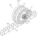
- FIG. 8 is a use state view of a differential transmission according to a third embodiment of the present inventive concept.
- a differential transmission 300 may include substantially the same structure as the differential transmission 100 of the first embodiment, that is, the pin-gear type main body unit 110 and the high-speed shaft connection unit 160, both being in the form of a pin gear.
- a second dummy input/output unit 372 that interacts with the pin-gear type main body unit 110 is provided in a rack gear type in which gear teeth 372a in a linear shape are formed.
- a linear motion may be performed through the second dummy input/output unit 372.
- FIG. 9 is a use state view of a differential transmission according to a fourth embodiment of the present inventive concept.
- a differential transmission 400 according to the present embodiment is rather different from the above-described embodiments.
- the differential transmission 400 according to the present embodiment may include a spur-gear type main body unit 410 and the high-speed shaft connection unit 160.
- the spur-gear type main body unit 410 may include a spur gear type main body housing 420 in which input or output is performed through a plurality of gear teeth 421 formed in the circumferential direction of the outer circumferential surface thereof, the high-speed shaft 130 (see FIG. 4 ) provided at one side of the spur gear type main body housing 420 and through which the input or output of the first speed that is a relatively high speed is performed, the low-speed shaft 140 (see FIG. 4 ) provided at the other side of the spur gear type main body housing 420 and through which the input or output of the second speed that is less than the first speed is performed, and the reduction portion 150 (see FIG. 4 ) provided inside the spur gear type main body housing 420 and through which an input speed is reduced.
- the spur-gear type main body unit 410 applied to the present embodiment is distinguished in that the spur-gear type main body unit 410 has a spur gear structure having the gear teeth 421, not a pin gear structure.
- the structures and functions of the high-speed shaft 130 (see FIG. 4 ), the low-speed shaft 140 (see FIG. 4 ), and the reduction portion 150 (see FIG. 4 ) which are mounted at positions in the spur gear type main body housing 420 are all the same as those of the first embodiment. Accordingly, the structures and functions are not described herein and are referred to the above-described embodiment.
- a curve of the gear teeth 421 formed on the spur-gear type main body unit 410 may form a cycloid curve or a trochoid curve.
- the high-speed shaft connection unit 160 connected to the spur-gear type main body unit 410 of the present embodiment is employed as the pin-gear type high-speed shaft connection unit 160 to which the pins 161 are rotatably coupled in the circumferential direction of the outer circumferential surface thereof.
- the first dummy input/output unit 171 and the second dummy input/output unit 172 that are connected to the spur-gear type main body unit 410 and the pin-gear type high-speed shaft connection unit 160 to interact with each other may be a spur gear type and a pin gear type, respectively.
- FIG. 10 is a use state view of a differential transmission according to a fifth embodiment of the present inventive concept.
- a differential transmission 500 according to the present embodiment has a slightly similar shape to the above-described fourth embodiment.
- the differential transmission 500 according to the present embodiment may include the spur-gear type main body unit 410 and the high-speed shaft connection unit 260.
- the spur-gear type main body unit 410 is the same as the above-described fourth embodiment.
- the high-speed shaft connection unit 260 applied to the present embodiment like the second embodiment of FIG. 7 , is employed as the spur-gear type high-speed shaft connection unit 260 on which the gear teeth 261 having a circular shape are formed in the circumferential direction of the outer circumferential surface thereof.
- a curve of the gear teeth 261 having a circular shape may form a cycloid curve or a trochoid curve.
- the first dummy input/output unit 271 and a second dummy input/output unit 472 that are connected to the spur-gear type main body unit 410 and the spur-gear type high-speed shaft connection unit 260 and interact with each other are all of a pin gear type.
- the present inventive concept is applicable for industrial machinery, semiconductor or flat display manufacturing equipment, various kinds of logistics equipment, etc., as well as various machine tools requiring a rotational motion or a linear motion.
Landscapes
- Engineering & Computer Science (AREA)
- General Engineering & Computer Science (AREA)
- Mechanical Engineering (AREA)
- Ocean & Marine Engineering (AREA)
- Retarders (AREA)
Applications Claiming Priority (2)
| Application Number | Priority Date | Filing Date | Title |
|---|---|---|---|
| KR1020180043459A KR102075980B1 (ko) | 2018-04-13 | 2018-04-13 | 차속 동력전달장치 |
| PCT/KR2019/003704 WO2019198957A1 (fr) | 2018-04-13 | 2019-03-29 | Transmission différentielle |
Publications (2)
| Publication Number | Publication Date |
|---|---|
| EP3779237A1 true EP3779237A1 (fr) | 2021-02-17 |
| EP3779237A4 EP3779237A4 (fr) | 2021-06-02 |
Family
ID=68162954
Family Applications (1)
| Application Number | Title | Priority Date | Filing Date |
|---|---|---|---|
| EP19785465.6A Ceased EP3779237A4 (fr) | 2018-04-13 | 2019-03-29 | Transmission différentielle |
Country Status (6)
| Country | Link |
|---|---|
| US (1) | US11333230B2 (fr) |
| EP (1) | EP3779237A4 (fr) |
| JP (1) | JP7108705B2 (fr) |
| KR (1) | KR102075980B1 (fr) |
| CN (1) | CN111971490B (fr) |
| WO (1) | WO2019198957A1 (fr) |
Families Citing this family (1)
| Publication number | Priority date | Publication date | Assignee | Title |
|---|---|---|---|---|
| KR102674835B1 (ko) * | 2022-01-24 | 2024-06-13 | (주)아이지비 | 동력전달장치 및 그 제조방법 |
Family Cites Families (17)
| Publication number | Priority date | Publication date | Assignee | Title |
|---|---|---|---|---|
| US5800305A (en) * | 1995-12-29 | 1998-09-01 | Koon-Woo Kang | Reduction gear with coaxial input and output shafts and combining planetary and nonplanetary gearing |
| JP2000097295A (ja) * | 1998-09-18 | 2000-04-04 | Metto Korea Co Ltd | 内接式遊星歯車減速機 |
| AU2009203285A1 (en) | 2008-01-08 | 2009-07-16 | Tae-Hwan Ha | Planetary gear set and power transmitting apparatus and use of the same |
| KR100945192B1 (ko) * | 2009-06-10 | 2010-03-03 | 주식회사 세진아이지비 | 동력전달장치 |
| GB2474039B (en) * | 2009-10-01 | 2016-02-17 | Michael Endean | Electric drive system |
| KR101009742B1 (ko) * | 2010-10-29 | 2011-01-19 | 주식회사 세진아이지비 | 동력전달장치 |
| FR2988012B1 (fr) * | 2012-03-13 | 2014-05-02 | Cie Engrenages Et Reducteurs Messian Durand | Dispositif d'entrainement et broyeur correspondant |
| KR101434483B1 (ko) * | 2012-08-14 | 2014-08-26 | 주식회사 하이코어 | 복수의 모터 결합을 위한 기어 장치 |
| KR101489933B1 (ko) * | 2013-08-12 | 2015-02-04 | 주식회사 하이코어 | 입력 합성 기어 시스템 |
| CN103062348A (zh) * | 2013-01-02 | 2013-04-24 | 北京工业大学 | 可消隙锥形齿滚销-次摆线齿条传动装置 |
| JP6407678B2 (ja) * | 2014-11-25 | 2018-10-17 | 武蔵精密工業株式会社 | 動力伝達装置 |
| KR101587833B1 (ko) * | 2015-01-20 | 2016-01-22 | 주식회사 세진아이지비 | 동력전달장치 |
| KR101746599B1 (ko) * | 2015-06-08 | 2017-06-14 | 주식회사 세진아이지비 | 내접식 유성치차 감속기 |
| KR101716453B1 (ko) * | 2015-09-30 | 2017-03-16 | 주식회사 세진아이지비 | 동력전달장치 |
| CN106555533A (zh) * | 2015-09-30 | 2017-04-05 | 德昌电机(深圳)有限公司 | 车窗升降机构 |
| KR101805576B1 (ko) * | 2016-09-01 | 2017-12-07 | 주식회사 세진아이지비 | 초고 감속용 유성치차 감속장치 |
| DE102018001795B4 (de) * | 2018-03-06 | 2024-02-01 | Brose Antriebstechnik GmbH & Co. Kommanditgesellschaft, Berlin | Antriebssystem |
-
2018
- 2018-04-13 KR KR1020180043459A patent/KR102075980B1/ko active Active
-
2019
- 2019-03-29 CN CN201980025673.3A patent/CN111971490B/zh active Active
- 2019-03-29 WO PCT/KR2019/003704 patent/WO2019198957A1/fr not_active Ceased
- 2019-03-29 EP EP19785465.6A patent/EP3779237A4/fr not_active Ceased
- 2019-03-29 JP JP2020554907A patent/JP7108705B2/ja not_active Expired - Fee Related
- 2019-03-29 US US17/041,436 patent/US11333230B2/en active Active
Also Published As
| Publication number | Publication date |
|---|---|
| CN111971490A (zh) | 2020-11-20 |
| US11333230B2 (en) | 2022-05-17 |
| KR20190119915A (ko) | 2019-10-23 |
| WO2019198957A1 (fr) | 2019-10-17 |
| US20210018080A1 (en) | 2021-01-21 |
| JP7108705B2 (ja) | 2022-07-28 |
| KR102075980B1 (ko) | 2020-02-12 |
| JP2021519895A (ja) | 2021-08-12 |
| EP3779237A4 (fr) | 2021-06-02 |
| CN111971490B (zh) | 2023-07-25 |
Similar Documents
| Publication | Publication Date | Title |
|---|---|---|
| US8967012B2 (en) | Double involute pinion-face gear drive system | |
| JP4609908B2 (ja) | 無段変速装置 | |
| US3546972A (en) | Profile shifted involute internal gearing | |
| JP2009121494A (ja) | 複段減速装置 | |
| KR20150012043A (ko) | 공액 이중 사이클로이드 치형을 갖는 차동식 감속기 | |
| CN116235388B (zh) | 摆线减速装置和电气设备 | |
| CN110630720A (zh) | 一种类摆线齿轮及类摆线齿轮减速器 | |
| JP6764042B2 (ja) | 中空型ハイポサイクロイド遊星減速機 | |
| WO2020034373A1 (fr) | Paire d'engrenages à goupilles cycloïdales dentées de face et dispositif de réduction de vitesse de nutation | |
| CN212985943U (zh) | 传动机构 | |
| WO2019090900A1 (fr) | Réducteur de vitesse cycloïdal précis pour articulation rotative | |
| EP2522880B1 (fr) | Transmission à engrenages | |
| CN116075654B (zh) | 周摆线齿轮减速器 | |
| CN212928677U (zh) | 传动机构 | |
| US11333230B2 (en) | Differential transmission | |
| WO2018168763A1 (fr) | Engrenage de réduction différentielle | |
| CN110966356A (zh) | 少齿差行星减速器 | |
| CN107477151A (zh) | 内啮合传动机构 | |
| TWI856451B (zh) | 減速機改良結構 | |
| CN208686917U (zh) | 新型柔性补偿型齿轮机器人减速器 | |
| JP2016098943A (ja) | 動力伝達装置 | |
| WO2019113778A1 (fr) | Réducteur de vitesse planétaire cycloïdal et outillage d'équipement mécanique | |
| JP7824699B1 (ja) | 差動歯車機構 | |
| KR20090022523A (ko) | 헤리컬 유성감속기 | |
| TWI909855B (zh) | 減速機結構 |
Legal Events
| Date | Code | Title | Description |
|---|---|---|---|
| STAA | Information on the status of an ep patent application or granted ep patent |
Free format text: STATUS: THE INTERNATIONAL PUBLICATION HAS BEEN MADE |
|
| PUAI | Public reference made under article 153(3) epc to a published international application that has entered the european phase |
Free format text: ORIGINAL CODE: 0009012 |
|
| STAA | Information on the status of an ep patent application or granted ep patent |
Free format text: STATUS: REQUEST FOR EXAMINATION WAS MADE |
|
| 17P | Request for examination filed |
Effective date: 20200917 |
|
| AK | Designated contracting states |
Kind code of ref document: A1 Designated state(s): AL AT BE BG CH CY CZ DE DK EE ES FI FR GB GR HR HU IE IS IT LI LT LU LV MC MK MT NL NO PL PT RO RS SE SI SK SM TR |
|
| AX | Request for extension of the european patent |
Extension state: BA ME |
|
| REG | Reference to a national code |
Ref country code: DE Ref legal event code: R079 Free format text: PREVIOUS MAIN CLASS: F16H0001320000 Ipc: F16H0003720000 |
|
| A4 | Supplementary search report drawn up and despatched |
Effective date: 20210506 |
|
| RIC1 | Information provided on ipc code assigned before grant |
Ipc: F16H 3/72 20060101AFI20210429BHEP Ipc: F16H 1/32 20060101ALN20210429BHEP Ipc: F16H 55/10 20060101ALN20210429BHEP Ipc: F16H 19/04 20060101ALN20210429BHEP Ipc: F16H 37/04 20060101ALN20210429BHEP Ipc: F16H 57/04 20100101ALN20210429BHEP Ipc: F16H 1/24 20060101ALN20210429BHEP |
|
| DAV | Request for validation of the european patent (deleted) | ||
| DAX | Request for extension of the european patent (deleted) | ||
| STAA | Information on the status of an ep patent application or granted ep patent |
Free format text: STATUS: EXAMINATION IS IN PROGRESS |
|
| 17Q | First examination report despatched |
Effective date: 20220919 |
|
| REG | Reference to a national code |
Ref country code: DE Ref legal event code: R003 |
|
| STAA | Information on the status of an ep patent application or granted ep patent |
Free format text: STATUS: THE APPLICATION HAS BEEN REFUSED |
|
| 18R | Application refused |
Effective date: 20231110 |