EP3779271A1 - Lampe et lampe d'exploitation minière - Google Patents
Lampe et lampe d'exploitation minière Download PDFInfo
- Publication number
- EP3779271A1 EP3779271A1 EP18912522.2A EP18912522A EP3779271A1 EP 3779271 A1 EP3779271 A1 EP 3779271A1 EP 18912522 A EP18912522 A EP 18912522A EP 3779271 A1 EP3779271 A1 EP 3779271A1
- Authority
- EP
- European Patent Office
- Prior art keywords
- lamp
- reflector
- lamp housing
- reflective
- reflective surfaces
- Prior art date
- Legal status (The legal status is an assumption and is not a legal conclusion. Google has not performed a legal analysis and makes no representation as to the accuracy of the status listed.)
- Withdrawn
Links
Images


Classifications
-
- F—MECHANICAL ENGINEERING; LIGHTING; HEATING; WEAPONS; BLASTING
- F21—LIGHTING
- F21V—FUNCTIONAL FEATURES OR DETAILS OF LIGHTING DEVICES OR SYSTEMS THEREOF; STRUCTURAL COMBINATIONS OF LIGHTING DEVICES WITH OTHER ARTICLES, NOT OTHERWISE PROVIDED FOR
- F21V7/00—Reflectors for light sources
- F21V7/04—Optical design
- F21V7/048—Optical design with facets structure
-
- F—MECHANICAL ENGINEERING; LIGHTING; HEATING; WEAPONS; BLASTING
- F21—LIGHTING
- F21L—LIGHTING DEVICES OR SYSTEMS THEREOF, BEING PORTABLE OR SPECIALLY ADAPTED FOR TRANSPORTATION
- F21L4/00—Electric lighting devices with self-contained electric batteries or cells
-
- F—MECHANICAL ENGINEERING; LIGHTING; HEATING; WEAPONS; BLASTING
- F21—LIGHTING
- F21V—FUNCTIONAL FEATURES OR DETAILS OF LIGHTING DEVICES OR SYSTEMS THEREOF; STRUCTURAL COMBINATIONS OF LIGHTING DEVICES WITH OTHER ARTICLES, NOT OTHERWISE PROVIDED FOR
- F21V23/00—Arrangement of electric circuit elements in or on lighting devices
- F21V23/003—Arrangement of electric circuit elements in or on lighting devices the elements being electronics drivers or controllers for operating the light source, e.g. for a LED array
-
- F—MECHANICAL ENGINEERING; LIGHTING; HEATING; WEAPONS; BLASTING
- F21—LIGHTING
- F21V—FUNCTIONAL FEATURES OR DETAILS OF LIGHTING DEVICES OR SYSTEMS THEREOF; STRUCTURAL COMBINATIONS OF LIGHTING DEVICES WITH OTHER ARTICLES, NOT OTHERWISE PROVIDED FOR
- F21V7/00—Reflectors for light sources
- F21V7/0075—Reflectors for light sources for portable lighting devices
-
- F—MECHANICAL ENGINEERING; LIGHTING; HEATING; WEAPONS; BLASTING
- F21—LIGHTING
- F21V—FUNCTIONAL FEATURES OR DETAILS OF LIGHTING DEVICES OR SYSTEMS THEREOF; STRUCTURAL COMBINATIONS OF LIGHTING DEVICES WITH OTHER ARTICLES, NOT OTHERWISE PROVIDED FOR
- F21V7/00—Reflectors for light sources
- F21V7/04—Optical design
-
- F—MECHANICAL ENGINEERING; LIGHTING; HEATING; WEAPONS; BLASTING
- F21—LIGHTING
- F21S—NON-PORTABLE LIGHTING DEVICES; SYSTEMS THEREOF; VEHICLE LIGHTING DEVICES SPECIALLY ADAPTED FOR VEHICLE EXTERIORS
- F21S9/00—Lighting devices with a built-in power supply; Systems employing lighting devices with a built-in power supply
- F21S9/02—Lighting devices with a built-in power supply; Systems employing lighting devices with a built-in power supply the power supply being a battery or accumulator
-
- F—MECHANICAL ENGINEERING; LIGHTING; HEATING; WEAPONS; BLASTING
- F21—LIGHTING
- F21W—INDEXING SCHEME ASSOCIATED WITH SUBCLASSES F21K, F21L, F21S and F21V, RELATING TO USES OR APPLICATIONS OF LIGHTING DEVICES OR SYSTEMS
- F21W2131/00—Use or application of lighting devices or systems not provided for in codes F21W2102/00-F21W2121/00
- F21W2131/40—Lighting for industrial, commercial, recreational or military use
- F21W2131/402—Lighting for industrial, commercial, recreational or military use for working places
-
- F—MECHANICAL ENGINEERING; LIGHTING; HEATING; WEAPONS; BLASTING
- F21—LIGHTING
- F21Y—INDEXING SCHEME ASSOCIATED WITH SUBCLASSES F21K, F21L, F21S and F21V, RELATING TO THE FORM OR THE KIND OF THE LIGHT SOURCES OR OF THE COLOUR OF THE LIGHT EMITTED
- F21Y2115/00—Light-generating elements of semiconductor light sources
- F21Y2115/10—Light-emitting diodes [LED]
Definitions
- the present disclosure relates to the technical field of lighting equipment, for example, to a lamp and a mining lamp.
- Alight emitting diode (LED) light source is used in a mining lamp.
- LED lamp When an LED lamp is used as the light source of a downlight, the service life and luminous efficiency of the light source can be significantly improved, but glare is easily caused due to the concentrated light beam and the small irradiation area of the LED lamp.
- reflectors used in the mining lamp are all integrally smooth reflective mirror surfaces, this kind of mirror surface generates a light-focusing effect on the light emitted by the mining lamp, but the light emitted is uneven and the light spot generated is small, which brings fatigue influence on people's eyes. Especially in a working environment under the mine, the light-focusing effect and the small light spot generated by the light emitted by the mining lamp will bring inconvenience to the miners in their work.
- the present disclosure provides a lamp and a mining lamp, so as to solve problems of a small irradiation area, uneven light emission and generating a light-focusing effect of the related mining lamp.
- the present disclosure provides a lamp including a reflector.
- the reflector is a spherical or bowl-shaped structure, an inner wall of the reflector is provided with reflective layers in a honeycomb or scaly shape, the reflective layers include a plurality of rows of reflective surfaces arranged in the honeycomb or scaly shape, and all of the plurality of rows of reflective surfaces are of surface reflection.
- a shape of each of the plurality of rows of reflective surfaces is a polygon.
- the lamp further includes a lamp housing.
- the lamp housing includes a first lamp housing and a second lamp housing, and the reflector is detachably disposed inside the first lamp housing.
- the first lamp housing is provided with a protrusion
- the second lamp housing is provided with a groove
- the first lamp housing is fixedly disposed on the second lamp housing through a plug-in fit between the protrusion and the groove.
- the protrusion and the groove are fixed by glue, a screw or a buckle.
- At least one mounting hole is disposed in the first lamp housing, at least one first positioning hole is disposed at a first end of the reflector, and the at least one mounting hole is fixed to the at least one first positioning hole through a connecting piece.
- a circuit board is disposed in the second lamp housing, at least one second positioning hole is disposed on the circuit board, at least one positioning post is disposed at a second end of the reflector, and the at least one positioning post is fixed in the at least one second positioning hole.
- the lamp further includes a battery connected to a light emitting diode (LED) light source through the circuit board.
- LED light emitting diode
- a number of reflective surfaces in each of the reflective layers is same.
- a number of reflective surfaces in each of the reflective layers is not same.
- the present disclosure further provides a mining lamp, the mining lamp includes the lamp and an LED light source, and the LED light source is disposed on a recessed portion of a reflector of the lamp.
- distances from all reflective surfaces in a same reflective layer of the lamp to the LED light source are same.
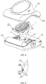
- the present disclosure provides a mining lamp with large light spot effect, and the mining lamp includes a reflector 1, an LED light source 2, and a lamp housing 3.
- the LED light source 2 is mounted on a recessed portion of the reflector 1 (for a bowl-shaped structure, the recessed portion is a bottom of an inner wall of the reflector 1; and for a spherical structure, the recessed portion is a bottom or a top of an inner wall of the reflector 1, and the top or bottom is determined only by the angle of view),
- the lamp housing 3 includes a first lamp housing 31 and a second lamp housing 32, the reflector 1 is detachably mounted inside the first lamp housing 31, and the first lamp housing 31 is mounted on the second lamp housing 32.
- the present disclosure further provides a lamp including a reflector 1, which may be a spherical or bowl-shaped structure.
- the reflector 1 is the spherical structure.
- An inner wall of the reflector 1 is provided with reflective layers distributed in a honeycomb or scaly shape, the reflective layers include a plurality of rows of reflective surfaces arranged in the honeycomb or scaly shape, and the plurality of rows of reflective surfaces are all of surface reflections.
- all the reflective surfaces may be processed as mirror surfaces (that is, all the reflective surfaces are of specular reflection).
- a number of reflective surfaces in each of the reflective layers is same, or a number of reflective surfaces in each of the reflective layers may be different. Whether the number of reflective surfaces in each of the reflective layers is same is determined according to the actual application situation. The effect of large irradiation area and even light emission can be achieved according to the mining lamp provided by the embodiment of the present disclosure.
- the present disclosure configures that the number of each row of reflective surfaces in the honeycomb or scaly reflective layers is same, such that beam angles of the light emitted by the LED light source 2 after being reflected by the honeycomb reflective surface on the inner wall of the reflector 1 are same, enlarging an irradiation range and generating a relatively soft large light spot effect, thereby enabling people to work under the light with a comfortable feeling.
- the reflective surface is processed as the mirror surface, such that light irradiated to the processed surface by the LED light source 2 is subjected to directional specular reflection instead of diffuse reflection, thereby achieving even light mixing. Moreover, this processing has advantages of small light energy loss, high reflective light efficiency, controllable direction of reflective light and high utilization rate of light source.
- distances from all reflective surfaces in each of the reflective layers to the LED light source 2 are same.
- the honeycomb reflective surface of each layer is placed at a corresponding position after amplifying the honeycomb reflective surface by a certain magnification according to a parabola, such that the number of honeycomb reflective surfaces of each layer can be ensured to be same.
- distances from all reflective surfaces of the same reflective layer of the lamp to the LED light source 2 are not same.
- the shape of each of the reflective surfaces is a polygon, such as a hexagon, octagon, or rhombus.
- the shape of the reflective surfaces which satisfy that the number of reflective surfaces in each layer of the reflective layers is same, may be taken as the shape the reflective surface of the present disclosure.
- the shape of the reflective surfaces arranged in the honeycomb shape is the hexagon.
- FIG. 1b is a partial structure view of a lamp according to an embodiment of the present disclosure, the shape of the reflective surface being the hexagon is described as an example, and one row of reflective surfaces may be understood as a plurality of reflective surfaces arranged in one latitude direction (not limited to three reflective surfaces in the figure).
- partial reflective surfaces of a first latitude direction, partial reflective surfaces of a second latitude direction, and partial reflective surfaces of a third latitude direction are using as an example to respectively represent a first row of reflective surfaces, a second row of reflective surfaces, and a third row of reflective surfaces.
- the above-mentioned three rows of reflective surfaces constitute a plurality of rows of reflective surfaces arranged in the honeycomb shape, and may be understood as that the reflective surfaces are respectively arranged in a plurality of latitude directions, each of the reflective layers includes a plurality of reflective surfaces, and the plurality of rows of reflective surfaces constitute the honeycomb shape as a whole.
- FIG. 1c is a partial structure view of the lamp from a first angle according to an embodiment of the present disclosure.
- at least one first positioning hole 11 is disposed at a first end of the reflector 1, and the reflector 1 is fixed on the lamp housing 3 through the at least one first positioning hole 11.
- FIG. 1d is a top view of a partial structure of the mining lamp according to an embodiment of the present disclosure. Referring to FIG. 1d , the LED light source is disposed in a center of a recessed portion of the reflector 1.
- the first lamp housing 31 is provided with a protrusion 311
- the second lamp housing 32 is provided with a groove 321
- the first lamp housing 31 is fixedly disposed on the second lamp housing 32 through a plug-in fit between the protrusion 311 and the groove 3.
- Such configuration can ensure that the assembly of the lamp housing 3 is more convenient and cost-saving.
- glue 322 is filled between the protrusion 311 and the groove 321, such that the first lamp housing 31 and the second lamp housing 32 can be fixed more tightly.
- the first lamp housing 31 and the second lamp housing 32 may be fixed by a screw or a buckle.
- At least one mounting hole (not shown in the figure) is disposed in the first lamp housing 31, at least one first positioning hole 11 is disposed at the first end of the reflector 1, and the at least one mounting hole is fixed to the at least one first positioning hole 11 through a connecting piece.
- the connecting piece may be a bolt or a fixing post.
- the number of mounting holes is the same as the number of first positioning holes 11.
- a circuit board 21 is disposed in the second lamp housing 32, at least one second positioning hole 22 is disposed on the circuit board 21, at least one positioning post 12 is disposed at a second end of the reflector 1, and the at least one positioning post 12 is fixed in the at least one second positioning hole 22. Due to a top end and a bottom end of the reflector 1 are fixed to the first lamp housing 31 and the second lamp housing 32, respectively, the reflector 1 can be ensured to be more stable.
- the number of positioning posts 12 is the same as the number of second positioning holes 22.
- the first end of the reflector 1 may be understood as one end far away from the recessed portion of the reflector 1, and the second end of the reflector 1 may be understood as one end close to the recessed portion of the reflector 1.
- the first end of the reflector 1 is provided with at least one first positioning hole 11, and the circuit board 21 is not provided with the second positioning hole 22, that is, the position of the reflector 1 can be fixed only through the first positioning hole 11.
- the circuit board 21 is provided with at least one second positioning hole 22, and the first end of the reflector 1 is not provided with the first positioning hole 11, that is, the position of the reflector 1 can be fixed only through the second positioning hole 22.
- the first end of the reflector 1 is provided with at least one first positioning hole 11
- the circuit board 21 is provided with at least one second positioning hole 22, that is, the position of the reflector 1 can be fixed through the first positioning hole 11 and the second positioning hole 22.
- the lamp further includes a battery 33 connected to the LED light source 2 through the circuit board 21.
- the battery 33 can be directly introduced alternating current mains supply or a low-voltage power supply to supply power to an LED power supply 2 in a constant current, such that the light emission is stable, stroboflash will not occur, and near infrared rays and ultraviolet rays are not included.
- the lamp provided by the present disclosure may further incorporate other lighting sources such as bulbs or fluorescent lamps.
- the lamp provided by the present disclosure is not limited being applied to the mining lamp, but may also be used in a variety of application scenarios such as hanging lamps, wall lamps, pendant lamps, ceiling lights, down lights, or project lamps.
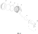
- FIG. 4 is an exploded view of another mining lamp according to an embodiment of the present disclosure.
- a lampshade 41, a transparent mirror surface 42 and a sealing ring 43 are disposed on the reflector 1 sequentially, and the reflector 1 is fixedly mounted on a lamp cap housing 44.
- the reflector 1 may be fixedly mounted on the lamp cap housing 44 by screws.
- the mining lamp is connected to a battery compartment 46 through a cable 45, and the battery compartment 46 is configured to supply power for a light source of the mining lamp.
- a length of the cable 45 may be set according to the actual reference, and the length of the cable 45 is not limited in FIG. 4 .
- the cable 45 is continuous, and only a cross section of the cable 45 is shown in FIG. 4 , which does not represent that the cable 45 is broken.
- the light beam angles of the light emitted by the LED light source after being reflected by the reflective surfaces on the inner wall of the reflector are same, which enlarges the irradiation range and generates the relatively soft large light spot effect, thereby enabling people to work under the light with a comfortable feeling.
- the light from the LED light source irradiated to the processed surface is subjected to the directional surface reflection, thereby achieving the effect of uniform light mixing.
- this processing has advantages of small light energy loss, high reflective light efficiency, controllable direction of reflective light and high utilization rate of light source.
Landscapes
- Engineering & Computer Science (AREA)
- General Engineering & Computer Science (AREA)
- Microelectronics & Electronic Packaging (AREA)
- Non-Portable Lighting Devices Or Systems Thereof (AREA)
Applications Claiming Priority (2)
| Application Number | Priority Date | Filing Date | Title |
|---|---|---|---|
| CN201810294518.9A CN108534048A (zh) | 2018-03-30 | 2018-03-30 | 一种具有大光斑效果的工矿灯 |
| PCT/CN2018/116884 WO2019184402A1 (fr) | 2018-03-30 | 2018-11-22 | Lampe et lampe d'exploitation minière |
Publications (2)
| Publication Number | Publication Date |
|---|---|
| EP3779271A1 true EP3779271A1 (fr) | 2021-02-17 |
| EP3779271A4 EP3779271A4 (fr) | 2021-12-15 |
Family
ID=63481802
Family Applications (1)
| Application Number | Title | Priority Date | Filing Date |
|---|---|---|---|
| EP18912522.2A Withdrawn EP3779271A4 (fr) | 2018-03-30 | 2018-11-22 | Lampe et lampe d'exploitation minière |
Country Status (4)
| Country | Link |
|---|---|
| US (1) | US20210148543A1 (fr) |
| EP (1) | EP3779271A4 (fr) |
| CN (1) | CN108534048A (fr) |
| WO (1) | WO2019184402A1 (fr) |
Families Citing this family (2)
| Publication number | Priority date | Publication date | Assignee | Title |
|---|---|---|---|---|
| CN108534048A (zh) * | 2018-03-30 | 2018-09-14 | 深圳市中孚能电气设备有限公司 | 一种具有大光斑效果的工矿灯 |
| US11112106B1 (en) * | 2020-12-30 | 2021-09-07 | Shenzhen Zhongfuneng Electric Equipment Co., Ltd. | Cordless lamp |
Family Cites Families (12)
| Publication number | Priority date | Publication date | Assignee | Title |
|---|---|---|---|---|
| US20060274529A1 (en) * | 2005-06-01 | 2006-12-07 | Cao Group, Inc. | LED light bulb |
| CN102721013B (zh) * | 2012-06-05 | 2016-10-05 | 深圳市中孚能电气设备有限公司 | 一种工矿灯外壳及其粘接方法 |
| CN103196066B (zh) * | 2013-04-19 | 2014-10-22 | 深圳市实益达科技股份有限公司 | 窄光束led照明光学系统及其设计方法 |
| CN104214540B (zh) * | 2013-05-29 | 2016-06-01 | 海洋王(东莞)照明科技有限公司 | 一种led灯具 |
| CN203322872U (zh) * | 2013-06-03 | 2013-12-04 | 浙江旭升照明有限公司 | 碟形矿用隔爆型led巷道灯 |
| CN204201613U (zh) * | 2014-06-12 | 2015-03-11 | 深圳市德普威科技发展有限公司 | 一种led煤矿工坑道灯 |
| CN204805997U (zh) * | 2015-05-29 | 2015-11-25 | 宁波胜筹光电科技有限公司 | 一种有聚光作用的led灯 |
| CN105508997B (zh) * | 2015-07-23 | 2019-04-23 | 深圳市亚马逊光电科技有限公司 | 一种光学结构板及led照明装置 |
| CN205037259U (zh) * | 2015-10-22 | 2016-02-17 | 深圳市中孚能电气设备有限公司 | 一种工矿灯外壳 |
| CN105485553B (zh) * | 2016-01-15 | 2019-04-30 | 武汉市金运科技开发有限公司 | 一种佩戴式匀辅光工矿灯 |
| CN205938650U (zh) * | 2016-05-27 | 2017-02-08 | 深圳市德普威科技发展有限公司 | 一种led聚焦oled屏无线充电矿灯 |
| CN108534048A (zh) * | 2018-03-30 | 2018-09-14 | 深圳市中孚能电气设备有限公司 | 一种具有大光斑效果的工矿灯 |
-
2018
- 2018-03-30 CN CN201810294518.9A patent/CN108534048A/zh active Pending
- 2018-11-22 EP EP18912522.2A patent/EP3779271A4/fr not_active Withdrawn
- 2018-11-22 WO PCT/CN2018/116884 patent/WO2019184402A1/fr not_active Ceased
- 2018-11-22 US US17/043,776 patent/US20210148543A1/en not_active Abandoned
Also Published As
| Publication number | Publication date |
|---|---|
| CN108534048A (zh) | 2018-09-14 |
| US20210148543A1 (en) | 2021-05-20 |
| EP3779271A4 (fr) | 2021-12-15 |
| WO2019184402A1 (fr) | 2019-10-03 |
Similar Documents
| Publication | Publication Date | Title |
|---|---|---|
| CN102844620B (zh) | 面照明器具和面照明装置 | |
| US6932496B2 (en) | LED-based elevated omnidirectional airfield light | |
| WO2011111622A1 (fr) | Appareil d'éclairage | |
| US20130285531A1 (en) | Led light bulb with light scattering optics structure | |
| CN107614964B (zh) | 光束控制部件、发光装置及照明装置 | |
| US20170232694A1 (en) | Lighting optics for luminaires | |
| CN106524079A (zh) | 透镜及其应用的led灯 | |
| US20130100677A1 (en) | Lighting structure | |
| US20120314413A1 (en) | Constructive occlusion lighting system and applications thereof | |
| US20210148543A1 (en) | Lamp and mining lamp | |
| US8360605B2 (en) | LED luminaire | |
| CN107533158B (zh) | 光束控制部件、发光装置及照明装置 | |
| JP5512447B2 (ja) | 照明器具 | |
| JP2014075176A (ja) | Led照明装置 | |
| CN102767701B (zh) | Led广角度球泡灯 | |
| US20190211975A1 (en) | Bulbs with indirect illumination | |
| CN204678255U (zh) | 一种光学元件及具有该光学元件的照明灯具 | |
| JP6429672B2 (ja) | 発光装置及びこれを用いた照明器具 | |
| JP5558619B1 (ja) | 照明装置 | |
| CN217737011U (zh) | 一种多面发光且具有防眩光功能的景观照明灯具 | |
| JP5457576B1 (ja) | 照明装置 | |
| WO2016181789A1 (fr) | Organe de commande de faisceau de lumière, dispositif électroluminescent et dispositif d'éclairage | |
| WO2025027021A1 (fr) | Agencement de filaments à del | |
| US9605834B2 (en) | LED light assembly | |
| JP5714430B2 (ja) | 照明装置用アダプタ |
Legal Events
| Date | Code | Title | Description |
|---|---|---|---|
| STAA | Information on the status of an ep patent application or granted ep patent |
Free format text: STATUS: THE INTERNATIONAL PUBLICATION HAS BEEN MADE |
|
| PUAI | Public reference made under article 153(3) epc to a published international application that has entered the european phase |
Free format text: ORIGINAL CODE: 0009012 |
|
| STAA | Information on the status of an ep patent application or granted ep patent |
Free format text: STATUS: REQUEST FOR EXAMINATION WAS MADE |
|
| 17P | Request for examination filed |
Effective date: 20201029 |
|
| AK | Designated contracting states |
Kind code of ref document: A1 Designated state(s): AL AT BE BG CH CY CZ DE DK EE ES FI FR GB GR HR HU IE IS IT LI LT LU LV MC MK MT NL NO PL PT RO RS SE SI SK SM TR |
|
| AX | Request for extension of the european patent |
Extension state: BA ME |
|
| DAV | Request for validation of the european patent (deleted) | ||
| DAX | Request for extension of the european patent (deleted) | ||
| STAA | Information on the status of an ep patent application or granted ep patent |
Free format text: STATUS: THE APPLICATION HAS BEEN WITHDRAWN |
|
| A4 | Supplementary search report drawn up and despatched |
Effective date: 20211111 |
|
| RIC1 | Information provided on ipc code assigned before grant |
Ipc: F21W 131/402 20060101ALI20211105BHEP Ipc: F21V 7/04 20060101ALI20211105BHEP Ipc: F21S 9/02 20060101AFI20211105BHEP |
|
| 18W | Application withdrawn |
Effective date: 20211130 |