EP3779295A1 - Innenraumeinheit einer klimaanlage - Google Patents
Innenraumeinheit einer klimaanlage Download PDFInfo
- Publication number
- EP3779295A1 EP3779295A1 EP19775655.4A EP19775655A EP3779295A1 EP 3779295 A1 EP3779295 A1 EP 3779295A1 EP 19775655 A EP19775655 A EP 19775655A EP 3779295 A1 EP3779295 A1 EP 3779295A1
- Authority
- EP
- European Patent Office
- Prior art keywords
- outlet
- indoor unit
- side walls
- blow
- movable
- Prior art date
- Legal status (The legal status is an assumption and is not a legal conclusion. Google has not performed a legal analysis and makes no representation as to the accuracy of the status listed.)
- Granted
Links
Images







Classifications
-
- F—MECHANICAL ENGINEERING; LIGHTING; HEATING; WEAPONS; BLASTING
- F24—HEATING; RANGES; VENTILATING
- F24F—AIR-CONDITIONING; AIR-HUMIDIFICATION; VENTILATION; USE OF AIR CURRENTS FOR SCREENING
- F24F1/00—Room units for air-conditioning, e.g. separate or self-contained units or units receiving primary air from a central station
- F24F1/0007—Indoor units, e.g. fan coil units
- F24F1/0011—Indoor units, e.g. fan coil units characterised by air outlets
-
- F—MECHANICAL ENGINEERING; LIGHTING; HEATING; WEAPONS; BLASTING
- F04—POSITIVE - DISPLACEMENT MACHINES FOR LIQUIDS; PUMPS FOR LIQUIDS OR ELASTIC FLUIDS
- F04D—NON-POSITIVE-DISPLACEMENT PUMPS
- F04D17/00—Radial-flow pumps, e.g. centrifugal pumps; Helico-centrifugal pumps
- F04D17/02—Radial-flow pumps, e.g. centrifugal pumps; Helico-centrifugal pumps having non-centrifugal stages, e.g. centripetal
- F04D17/04—Radial-flow pumps, e.g. centrifugal pumps; Helico-centrifugal pumps having non-centrifugal stages, e.g. centripetal of transverse-flow type
-
- F—MECHANICAL ENGINEERING; LIGHTING; HEATING; WEAPONS; BLASTING
- F04—POSITIVE - DISPLACEMENT MACHINES FOR LIQUIDS; PUMPS FOR LIQUIDS OR ELASTIC FLUIDS
- F04D—NON-POSITIVE-DISPLACEMENT PUMPS
- F04D25/00—Pumping installations or systems
- F04D25/02—Units comprising pumps and their driving means
- F04D25/08—Units comprising pumps and their driving means the working fluid being air, e.g. for ventilation
- F04D25/12—Units comprising pumps and their driving means the working fluid being air, e.g. for ventilation the unit being adapted for mounting in apertures
- F04D25/14—Units comprising pumps and their driving means the working fluid being air, e.g. for ventilation the unit being adapted for mounting in apertures and having shutters, e.g. automatically closed when not in use
-
- F—MECHANICAL ENGINEERING; LIGHTING; HEATING; WEAPONS; BLASTING
- F04—POSITIVE - DISPLACEMENT MACHINES FOR LIQUIDS; PUMPS FOR LIQUIDS OR ELASTIC FLUIDS
- F04D—NON-POSITIVE-DISPLACEMENT PUMPS
- F04D27/00—Control, e.g. regulation, of pumps, pumping installations or pumping systems specially adapted for elastic fluids
- F04D27/002—Control, e.g. regulation, of pumps, pumping installations or pumping systems specially adapted for elastic fluids by varying geometry within the pumps, e.g. by adjusting vanes
-
- F—MECHANICAL ENGINEERING; LIGHTING; HEATING; WEAPONS; BLASTING
- F04—POSITIVE - DISPLACEMENT MACHINES FOR LIQUIDS; PUMPS FOR LIQUIDS OR ELASTIC FLUIDS
- F04D—NON-POSITIVE-DISPLACEMENT PUMPS
- F04D29/00—Details, component parts, or accessories
- F04D29/40—Casings; Connections of working fluid
- F04D29/42—Casings; Connections of working fluid for radial or helico-centrifugal pumps
- F04D29/44—Fluid-guiding means, e.g. diffusers
- F04D29/46—Fluid-guiding means, e.g. diffusers adjustable
- F04D29/462—Fluid-guiding means, e.g. diffusers adjustable especially adapted for elastic fluid pumps
- F04D29/464—Fluid-guiding means, e.g. diffusers adjustable especially adapted for elastic fluid pumps adjusting flow cross-section, otherwise than by using adjustable stator blades
-
- F—MECHANICAL ENGINEERING; LIGHTING; HEATING; WEAPONS; BLASTING
- F04—POSITIVE - DISPLACEMENT MACHINES FOR LIQUIDS; PUMPS FOR LIQUIDS OR ELASTIC FLUIDS
- F04D—NON-POSITIVE-DISPLACEMENT PUMPS
- F04D29/00—Details, component parts, or accessories
- F04D29/58—Cooling; Heating; Diminishing heat transfer
- F04D29/582—Cooling; Heating; Diminishing heat transfer specially adapted for elastic fluid pumps
- F04D29/5826—Cooling at least part of the working fluid in a heat exchanger
-
- F—MECHANICAL ENGINEERING; LIGHTING; HEATING; WEAPONS; BLASTING
- F04—POSITIVE - DISPLACEMENT MACHINES FOR LIQUIDS; PUMPS FOR LIQUIDS OR ELASTIC FLUIDS
- F04D—NON-POSITIVE-DISPLACEMENT PUMPS
- F04D29/00—Details, component parts, or accessories
- F04D29/66—Combating cavitation, whirls, noise, vibration or the like; Balancing
-
- F—MECHANICAL ENGINEERING; LIGHTING; HEATING; WEAPONS; BLASTING
- F24—HEATING; RANGES; VENTILATING
- F24F—AIR-CONDITIONING; AIR-HUMIDIFICATION; VENTILATION; USE OF AIR CURRENTS FOR SCREENING
- F24F1/00—Room units for air-conditioning, e.g. separate or self-contained units or units receiving primary air from a central station
- F24F1/0007—Indoor units, e.g. fan coil units
- F24F1/0018—Indoor units, e.g. fan coil units characterised by fans
- F24F1/0025—Cross-flow or tangential fans
-
- F—MECHANICAL ENGINEERING; LIGHTING; HEATING; WEAPONS; BLASTING
- F24—HEATING; RANGES; VENTILATING
- F24F—AIR-CONDITIONING; AIR-HUMIDIFICATION; VENTILATION; USE OF AIR CURRENTS FOR SCREENING
- F24F1/00—Room units for air-conditioning, e.g. separate or self-contained units or units receiving primary air from a central station
- F24F1/0007—Indoor units, e.g. fan coil units
- F24F1/0043—Indoor units, e.g. fan coil units characterised by mounting arrangements
- F24F1/0057—Indoor units, e.g. fan coil units characterised by mounting arrangements mounted in or on a wall
-
- F—MECHANICAL ENGINEERING; LIGHTING; HEATING; WEAPONS; BLASTING
- F24—HEATING; RANGES; VENTILATING
- F24F—AIR-CONDITIONING; AIR-HUMIDIFICATION; VENTILATION; USE OF AIR CURRENTS FOR SCREENING
- F24F13/00—Details common to, or for air-conditioning, air-humidification, ventilation or use of air currents for screening
- F24F13/08—Air-flow control members, e.g. louvres, grilles, flaps or guide plates
- F24F13/10—Air-flow control members, e.g. louvres, grilles, flaps or guide plates movable, e.g. dampers
-
- F—MECHANICAL ENGINEERING; LIGHTING; HEATING; WEAPONS; BLASTING
- F24—HEATING; RANGES; VENTILATING
- F24F—AIR-CONDITIONING; AIR-HUMIDIFICATION; VENTILATION; USE OF AIR CURRENTS FOR SCREENING
- F24F13/00—Details common to, or for air-conditioning, air-humidification, ventilation or use of air currents for screening
- F24F13/20—Casings or covers
-
- F—MECHANICAL ENGINEERING; LIGHTING; HEATING; WEAPONS; BLASTING
- F05—INDEXING SCHEMES RELATING TO ENGINES OR PUMPS IN VARIOUS SUBCLASSES OF CLASSES F01-F04
- F05D—INDEXING SCHEME FOR ASPECTS RELATING TO NON-POSITIVE-DISPLACEMENT MACHINES OR ENGINES, GAS-TURBINES OR JET-PROPULSION PLANTS
- F05D2250/00—Geometry
- F05D2250/50—Inlet or outlet
- F05D2250/52—Outlet
-
- F—MECHANICAL ENGINEERING; LIGHTING; HEATING; WEAPONS; BLASTING
- F24—HEATING; RANGES; VENTILATING
- F24F—AIR-CONDITIONING; AIR-HUMIDIFICATION; VENTILATION; USE OF AIR CURRENTS FOR SCREENING
- F24F13/00—Details common to, or for air-conditioning, air-humidification, ventilation or use of air currents for screening
- F24F13/24—Means for preventing or suppressing noise
Definitions
- the present disclosure relates to an indoor unit of an air conditioner.
- Patent Document 1 describes an example of an impeller and a cross-flow fan that has a blow-out flow path which guides blown-out-air from the impeller to an outlet.
- Patent Document 1 Japanese Laid-Open Patent Publication No. 2009-121731
- One objective of the present disclosure is to provide an indoor unit of an air conditioner that limits decreases in the performance of the indoor unit.
- An indoor unit of an air conditioner that solves the above problems includes an indoor unit main body, a heat exchanger, and a cross-flow fan.
- the indoor unit main body includes an inlet and an outlet.
- the heat exchanger performs heat exchange on air drawn in from the inlet.
- the cross-flow fan is configured to blow out air, which has undergone heat exchange performed by the heat exchanger, from the outlet.
- the cross-flow fan includes a blow-out flow path formed by a lower wall, left and right side walls, and an upper wall so that a cross-sectional area gradually increases downward. The blow-out flow path guides blown-out air to the outlet.
- a ratio (L/D) of the distance L to outer diameter D of an impeller of the cross-flow fan is less than 0.05. At least part of the blow-out flow path is formed to project out of the outlet at least when an air conditioning operation is performed.
- This structure limits decreases in the ease of installation of the indoor unit main body and allows power consumption and noise to be reduced by increasing the outer diameter D of the impeller of the cross-flow fan. Also, at least part of the blow-out flow path projects out of the outlet so that the diffuser has a sufficient length. This maintains the functionality of the diffuser. Consequently, adverse effects on the performance of the indoor unit will be limited.
- the two side walls be arranged to project out of the outlet at least when an air conditioning operation is performed.
- the side walls restrict the air blown out of the outlet from flowing sideward from the outlet. This allows the blow-out flow path to be extended from the outlet. In this manner, the static pressure in the blow-out flow path is increased to increase the air volume of the blow-out flow path is increased. Further, when the air flow resistance (internal pressure loss) in the indoor unit main body is high, backflow of air from the two sideward ends of the outlet is restricted. Thus, surging is unlikely to occur.
- the lower wall be arranged to project out of the outlet at least when an air conditioning operation is performed.
- the lower wall restricts the air blown out of the outlet from flowing downward from the outlet.
- This allows the blow-out flow path to be extended from the outlet.
- the blow-out flow path serving as a diffuser is lengthened compared to a structure that does not project the upper wall out of the outlet.
- This further increases the static pressure in the blow-out flow path and further increases the air volume of the blow-out flow path.
- the air flow resistance (internal pressure loss) in the indoor unit main body is high, backflow of air from the lower part of the outlet is restricted. Thus, surging is even less likely to occur.
- the upper wall be arranged to project out of the outlet at least when an air conditioning operation is performed.
- the upper wall restricts the air blown out of the outlet from flowing upward from the outlet.
- This allows the blow-out flow path to be extended from the outlet.
- the blow-out flow path serving as a diffuser is lengthened compared to a structure that does not project the upper wall out of the outlet.
- This further increases the static pressure in the blow-out flow path and further increases the air volume of the blow-out flow path.
- the air flow resistance (internal pressure loss) in the indoor unit main body is high, backflow of air from the lower part of the outlet is restricted. Thus, surging is even less likely to occur.
- a ratio (H/D) of height H of the indoor unit main body to the outer diameter D of the impeller of the cross-flow fan be less than 2.2.
- the indoor unit main body uses the cross-flow fan including the impeller with a relatively large outer diameter. This allows noise and power consumption to be reduced when an air conditioning operation is performed.
- the indoor unit further include a movement mechanism configured to switch between a stored state that does not project an element forming the blow-out flow path out of the outlet and a projected state that projects at least part of the element out of the outlet.
- the movement mechanism is in the projected state when an air conditioning operation is performed and in the stored state when an air conditioning operation is stopped.
- the blow-out flow path projects out of the indoor unit main body when an air conditioning operation is performed. Thus, surging is unlikely to occur. Further, the blow-out flow path is stored in the indoor unit main body when an air conditioning operation is stopped. Thus, the aesthetic appearance of the indoor unit is improved.
- the indoor unit 1 of the present embodiment is of a wall-mounted type and includes a rear portion attached to an indoor wall WL.
- the indoor unit 1 is, for example, configured to perform a cooling operation that cools an indoor space and a heating operation that heats an indoor space.
- the indoor unit 1 includes an indoor unit main body 10.
- the indoor unit main body 10 has the form of a box, in which a lateral direction (sideward direction of indoor unit 1) coincides with the longitudinal direction, and includes an inner space surrounded by a top surface portion 11, a front surface portion 12, a rear surface portion 13, two side surface portions 14, and a bottom surface portion 15.
- the indoor unit 1 is mounted on the wall WL by coupling the rear surface portion 13 to a mounting panel (not shown) on the wall WL with screws or the like.
- the top surface portion 11 of the indoor unit main body 10 includes an inlet 16, and the bottom surface portion 15 includes an outlet 17.
- the inlet 16 and the outlet 17 are each arranged so that the lateral direction (sideward direction) coincides with the longitudinal direction.
- the inlet 16 is formed along the top surface portion 11.
- the outlet 17 is formed along the bottom surface portion 15.
- the indoor unit 1 includes an air filter 21, an indoor heat exchanger 22, a cross-flow fan 23, and a flap 24.
- the air filter 21, the indoor heat exchanger 22, and the cross-flow fan 23 are accommodated in the indoor unit main body 10.
- the air filter 21 is coupled to the indoor unit main body 10 in a removable manner.
- the air filter 21 removes dust from indoor air drawn in from the inlet 16.
- the air filter 21 is located between the top surface portion 11 and the indoor heat exchanger 22 of the indoor unit main body 10. In this manner, the air filter 21 limits the collection of dust, which is suspended in the indoor air, on the surface of the indoor heat exchanger 22.
- the indoor heat exchanger 22 includes a plurality of fins and a plurality of heat transfer tubes that extend through the fins.
- the indoor heat exchanger 22 serves as an evaporator or a condenser in accordance with an operation state of the indoor unit 1 and exchanges heat between a refrigerant flowing through the heat transfer tubes and air flowing through the indoor heat exchanger 22.
- the indoor heat exchanger 22 is arranged so that its front end and rear end are bent downward in a side view.
- the indoor heat exchanger 22 is arranged to surround the cross-flow fan 23 from above.
- the cross-flow fan 23 is located inside the indoor unit main body 10 at a substantially central portion.
- the cross-flow fan 23 includes an impeller 25 and a fan case 27.
- the impeller 25 is substantially cylindrical and has a lateral direction (sideward direction) that coincides with the longitudinal direction.
- the fan case 27 forms a blow-out flow path 26 that extends to the outlet 17.
- the blow-out flow path 26 is formed by a lower wall 26L, left and right side walls 26S, and an upper wall 26U in a manner so that its cross-sectional area gradually increases downward. In other words, the cross-sectional area of the blow-out flow path 26 increases toward the outlet 17. In this manner, the blow-out flow path 26 functions as a diffuser.
- the indoor air drawn in from the inlet 16 flows through the indoor heat exchanger 22 to the cross-flow fan 23. Then, the indoor air flows from the cross-flow fan 23 through the blow-out flow path 26 and is blown out of the outlet 17 into the room.
- the impeller 25 of the cross-flow fan 23 has an outer diameter D, and the rear surface portion 13 of the indoor unit main body 10 has a vertical dimension (up-down dimension) that corresponds to a height H of the indoor unit main body 10.
- the outer diameter D is 126 mm or greater and less than 150 mm. Further preferably, the outer diameter D is 135 mm or greater and less than 150 mm.
- the height H of the indoor unit main body 10 is 295 mm or less. Further preferably, the height H of the indoor unit main body 10 is 250 mm or greater and 295 mm or less.
- a ratio (H/D) of the height H of the indoor unit main body 10 to the outer diameter D is less than 2.2. Further preferably, the ratio (H/D) of the height H of the indoor unit main body 10 to the outer diameter D is 1.6 or greater and less than 2.2.
- the flap 24 is arranged at a lower edge of the outlet 17 and is pivotal relative to the indoor unit main body 10.
- the flap 24 has the form of a flat plate and its lateral direction (sideward direction) coincides with the longitudinal direction.
- the flap 24 has a length in the longitudinal direction that is substantially the same as that of the outlet 17.
- the flap 24 is configured to be pivoted by a flap driving motor 28 (refer to Fig. 3 ) about a rotation axis C1.
- the indoor unit 1 of the present embodiment includes a movement mechanism 29 that is configured to move the two side walls 26S of the blow-out flow path 26. More specifically, the two side walls 26S each include a fixed side wall 26SF and a movable side wall 26SM. The fixed side wall SF and the movable side wall 26SM are arranged to be overlapped with each other in the lateral direction (sideward direction). The movable side wall 26SM is configured to be movable so as to slide relative to the fixed side wall SF and project out of the outlet 17. The movement mechanism 29 moves the movable side walls 26SM.
- the movement mechanism 29 includes a first motor (not shown), which serves a drive source, and a rotation-linear movement conversion mechanism (not shown), which converts rotation of the first motor into linear movement in a predetermined direction.
- One example of the movement mechanism 29 is a feed-screw mechanism.
- the movement mechanism 29 in a state in which the movable side walls 26SM project out of the outlet 17, the movement mechanism 29 is configured to move the movable side walls 26SM so as to decrease the cross-sectional area between the left and right movable side walls 26SM.
- the movement mechanism 29 includes a second motor (not shown) that pivots each movable side wall 26SM about a rotation axis C2 (refer to Fig. 2B ).
- the movement mechanism 29 allows for switching between a restricted state, in which the cross-sectional area between the left and right movable side walls 26SM is decreased, and a normal state, in which the cross-sectional area between the left and right movable side walls 26SM is not decreased.
- the distance between the left and right movable side walls 26SM in the sideward direction at the projected end side is less than the sideward length of the outlet 17.
- the air conditioner includes an outdoor control unit 7 that controls each of a compressor 3 of an outdoor unit 2, a four-way switching valve 4, an outdoor fan 5, and an expansion valve 6.
- the outdoor control unit 7 controls the operational frequency (Hz) of the compressor 3, the rotational speed (rpm) of a motor of the outdoor fan 5, and the open degree of the expansion valve 6. Further, the outdoor control unit 7 switches the four-way switching valve 4 between a first state, in which a refrigerant circuit of the air conditioner (not shown) is in a cooling cycle, and a second state, in which the refrigerant circuit is in a heating cycle.
- the indoor unit 1 includes an indoor control unit 30.
- the indoor control unit 30 includes a processor and storage.
- the processor executes predetermined control programs, and the storage stores information used for various types of control programs and control processes.
- the processor includes, for example, a central processing unit (CPU) or a micro-processing unit (MPU).
- the storage includes, for example, a nonvolatile memory and a volatile memory.
- the non-volatile memory includes, for example, a read-only memory (ROM), a hard disk, and a flash memory.
- the volatile memory includes, for example, a random-access memory (RAM).
- the indoor control unit 30 may include one or more microcomputers.
- the outdoor control unit 7 may be configured in the same manner as the indoor control unit 30.
- the indoor control unit 30 is configured to establish wired or wireless communication with the outdoor control unit 7. Further, the indoor control unit 30 is configured to establish wireless communication with a remote controller 31.
- the indoor control unit 30 controls the cross-flow fan 23, the flap driving motor 28, and the movement mechanism 29 based on operation instructions from the remote controller 31. Further, the indoor control unit 30 transmits the contents of an operation instruction from the remote controller 31 to the outdoor control unit 7. Based on the operation instruction from the remote controller 31, the outdoor control unit 7 controls the operational frequency (Hz) of the compressor 3, the rotational speed (rpm) of the outdoor fan 5, the open degree of the expansion valve 6, and switching of the four-way switching valve 4 between the first state and the second state.
- Hz operational frequency
- rpm rotational speed
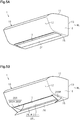
- the indoor control unit 30 of the present embodiment controls the movement mechanism 29 to switch between the stored state, in which the movable side walls 26SM do not project out of the outlet 17 as shown in Figs. 1A and 2A , and the projected state, in which the movable side walls 26SM project out of the outlet 17 as shown in Figs. 1B and 2B .
- the indoor control unit 30 controls the movement mechanism 29 to be in the projected state when an air conditioning operation is performed and controls the movement mechanism 29 to be in the stored state when an air conditioning operation is stopped.
- the movable side walls 26SM are configured to entirely cover transverse sides (up-down sides) of the outlet 17 in the projected state.
- the indoor control unit 30 controls the flap driving motor 28 so that the flap 24 covers the outlet 17 as shown in Figs. 1A and 2A . Further, when an air conditioning operation is performed, the indoor control unit 30 controls the flap driving motor 28 so that the flap 24 opens the outlet 17 as shown in Figs. 1B and 2B . In this manner, when an air conditioning operation is stopped, the indoor unit 1 shown in Figs. 1A and 2A is in a state in which the movable side walls 26SM and the flap 24 do not project out of the indoor unit main body 10. Further, when an air conditioning operation is performed, the indoor unit 1 shown in Figs. 1B and 2B is in a state in which the movable side walls 26SM and the flap 24 project out of the indoor unit main body 10.
- the pivotal position of the flap 24 can be freely changed.
- the pivotal position of the flap 24 is changeable by an instruction from the remote controller 31.
- the indoor control unit 30 controls the movement mechanism 29 in the restricted state to decrease the cross-sectional area between the left and right movable side walls 26SM with the second motor that pivots each movable side wall 26SM about the rotation axis C2 (refer to Fig. 2B ).
- the cross-sectional area of the blow-out flow path 26 at a downstream side of the outlet 17 is smaller than the cross-sectional area of the outlet 17. This increases the velocity of the indoor air in the blow-out flow path 26 and impedes surging.
- the indoor control unit 30 controls the movement mechanism 29 to switch from the restricted state to the normal state with the second motor.
- surging refers to noise (for example, rustling noise) produced when the volume or pressure of the indoor air blown out of the outlet 17 becomes unstable and backflow forms at the outlet 17. Surging is likely to occur, for example, when the air filter 21 is clogged with dust and the air flow resistance is increased or when condensation is formed on the indoor heat exchanger 22.
- noise for example, rustling noise
- surging is detected from the rotational speed (rpm) of a fan motor (not shown) of the cross-flow fan 23. More specifically, the indoor control unit 30 sets the rotational speed of the fan motor in accordance with the operation instruction from the remote controller 31.
- the rotational speed of the fan motor that is set will be referred to as the set rotational speed.
- the indoor control unit 30 determines whether the rotational speed of the fan motor is in a tolerable rotational speed range that has a predetermined width centered on the set rotational speed. When the rotational speed of the fan motor is in the tolerable rotational speed range, the rotational speed of the fan motor is stable and the volume and pressure of the indoor air are less likely to be unstable.
- the indoor control unit 30 determines that surging has not occurred.
- the rotational speed of the motor is outside the tolerable rotational speed range, the rotational speed of the fan motor is unstable and the volume and pressure of the indoor air are likely to be unstable. Accordingly, the indoor control unit 30 determines that surging has occurred.
- the predetermined width is used to determine whether surging has occurred due to variations in the rotational speed of the fan motor and is set in advance through tests or the like.
- surging may be detected from the current supplied to the fan motor of the cross-flow fan 23. More specifically, the indoor control unit 30 determines whether the current supplied to the fan motor is in a tolerable current range that has a predetermined width centered on a current value corresponding to the set rotational speed. When the current supplied to the fan motor is in the tolerable current range, the volume and pressure of the indoor air are stable and the current supplied to the fan motor is stable. Accordingly, the indoor control unit 30 determines that surging has not occurred. When the current supplied to the fan motor is outside the tolerable current range, the volume and pressure of the indoor air are unstable and the current supplied to the fan motor is unstable. Accordingly, the indoor control unit 30 determines that surging has occurred.
- the predetermined width is used to determine whether surging has occurred due to variations in the current supplied to the fan motor and is set in advance through tests or the like.
- This movement control is executed over a period of time from when an air conditioning operation starts to when it ends.
- step S11 the indoor control unit 30 determines whether to start an air conditioning operation. In one example, when an operation start instruction has been received from the remote controller 31, the indoor control unit 30 determines to start an air conditioning operation. Further, when an operation start instruction has not been received, the indoor control unit 30 determines not to start an air conditioning operation.
- step S11: NO the indoor control unit 30 determines not to start an air conditioning operation
- step S11: NO the indoor control unit 30 ends the process.
- the movable side walls 26SM are maintained to be in the stored state.
- step S11: YES the indoor control unit 30 sets the movable side walls 26SM in the projected state in step 12. This projects the movable side walls 26SM out of the outlet 17.
- step S13 the indoor control unit 30 determines whether surging has occurred.
- the indoor control unit 30 controls the second motor of the movement mechanism 29 to switch to the restricted state, in which the cross-sectional area between the left and right movable side walls 26SM is decreased, in step S14. Then, in step S15, the indoor control unit 30 determines whether to end the air conditioning operation. In one example, when an operation end instruction has been received from the remote controller 31, the indoor control unit 30 determines to end the air conditioning operation. Further, when an operation end instruction has not been received, the indoor control unit 30 determines not to end the air conditioning operation.
- step S15: NO the indoor control unit 30 proceeds to step S13.
- step S15: YES the indoor control unit 30 sets the movable side walls 26SM in the stored state in step S16. This stores the movable side walls 26SM in the indoor unit main body 10.
- step S13 the indoor control unit 30 determines whether the movable side walls 26SM are in the restricted state in step S17.
- the indoor control unit 30 changes the movable side walls 26SM to the normal state in step S18 and then proceeds to step S15.
- the indoor control unit 30 maintains the movable side walls 26SM in the normal state and then proceeds to step S15.
- the region that defines the blow-out flow path 26 of the cross-flow fan 23 in the indoor unit main body 10 would be decreased and the blow-out flow path 26 would be shortened.
- the blow-out flow path 26 is shortened, the dynamic pressure of the indoor air will not be sufficiently converted into the static pressure in the blow-out flow path 26. This would decrease the air volume and pressure in the cross-flow fan 23.
- the velocity of the indoor air in the blow-out flow path 26 will be decreased and backflow from the outlet 17 is likely to be generated.
- backflow of indoor air from the outlet 17 may cause surging that destabilizes the flow of the indoor air blown out of the cross-flow fan 23.
- the velocity of indoor air at the two sideward ends of the outlet 17 is slower than that at a laterally central part of the outlet 17. Accordingly, backflow from the outlet 17 is more likely to be generated at the two sideward ends of the outlet 17.
- the movable side walls 26SM project out of the outlet 17 when an air conditioning operation is performed.
- This allows the blow-out flow path 26 to be extended by an amount corresponding to the length of the movable side walls 26SM.
- the movable side walls 26SM extend from the two sideward ends of the outlet 17 to project out of the outlet 17. This limits backflow of indoor air into the outlet 17 from an outer side of the two sideward ends of the outlet 17. Consequently, surging is impeded and changes in the air volume and pressure in the cross-flow fan 23 are limited.
- the present embodiment has the following advantages.
- the indoor unit 1 of an air conditioner in accordance with a second embodiment differs from the indoor unit 1 of the first embodiment in that the lower wall 26L of the blow-out flow path 26 is projected out of the outlet 17 together with the two side walls 26S when an air conditioning operation is performed.
- same reference numerals are given to those elements that are the same as the indoor unit 1 of the first embodiment. Such elements will not be described in detail.
- the lower wall 26L includes a fixed lower wall 26LF and a movable lower wall 26LM.
- the flap 24 is coupled to a distal end of the movable lower wall 26LM and is pivotal relative to the movable lower wall 26LM.
- the fixed lower wall 26LF and the movable lower wall 26LM are overlapped with each other in the vertical direction (up-down direction).
- the movable lower wall 26LM is configured to be movable so as to slide relative to the fixed lower wall 26LF and project out of the outlet 17.
- the movement mechanism 29 of the present embodiment is configured to move the movable side walls 26SM and the movable lower wall 26LM.
- the movement mechanism 29 is configured to move and slide the movable side walls 26SM relative to the fixed side walls SF and move and slide the movable lower wall 26LM relative to the fixed lower wall 26LF.
- the movement mechanism 29 includes a first motor, a first rotation-linear movement conversion mechanism that converts rotation of the first motor into linear movement of the movable side walls 26SM, and a second rotation-linear movement conversion mechanism that converts rotation of the first motor into linear movement of the movable lower wall 26LM.
- the movement mechanism 29 of the present embodiment moves the movable side walls 26SM and the movable lower wall 26LM with a single drive source.
- the indoor control unit 30 of the present embodiment controls the movement mechanism 29 to switch between a stored state, in which the movable side walls 26SM and the movable lower wall 26LM do not project out of the outlet 17 as shown in Figs. 5A and 6A , and a projected state, in which the movable side walls 26SM and the movable lower wall 26LM project out of the outlet 17 as shown in Figs. 5B and 6B .
- the indoor control unit 30 controls the movement mechanism 29 in the projected state when an air conditioning operation is performed and controls the movement mechanism 29 in the stored state when an air conditioning operation is stopped.
- the movable side walls 26SM are located above the sideward ends of the movable lower wall 26LM.
- the movable side walls SM are arranged so that no gap is formed between the movable side walls 26SM and the movable lower wall 26LM in the vertical direction. Further, each movable side wall 26SM is pivotal about the rotation axis C2 between the upper wall 26U and the movable lower wall 26LM.
- the relationship of the outer diameter D of the impeller 25 of the cross-flow fan 23 and the height H of the indoor unit main body 10 of the present embodiment is the same as the relationship of the outer diameter D of the impeller 25 of the cross-flow fan 23 and the height H of the indoor unit main body 10 of the first embodiment.
- the present embodiment has the following advantages in addition to the advantages of the first embodiment.
- the indoor unit 1 of an air conditioner in accordance with a third embodiment differs from the indoor unit 1 of the second embodiment in that the upper wall 26U projects out of the outlet 17 together with the two side walls 26S and the lower wall 26L of the blow-out flow path 26 when an air conditioning operation is performed.
- same reference numerals are given to those elements that are the same as the indoor unit 1 of the second embodiment. Such elements will not be described in detail.
- the upper wall 26U of the present embodiment includes a fixed upper wall 26UF and a movable upper wall 26UM.
- the fixed upper wall 26UF and the movable upper wall 26UM are overlapped with each other in the vertical direction (up-down direction).
- the movable upper wall 26UM is configured to be movable so as to slide relative to the fixed upper wall 26UF and project out of the outlet 17.
- the movement mechanism 29 of the present embodiment is configured to move the movable side walls 26SM, the movable lower wall 26LM, and the movable upper wall 26UM.
- the movement mechanism 29 is configured to move and slide the movable side walls 26SM relative to the fixed side walls SF, move and slide the movable lower wall 26LM relative to the fixed lower wall 26LF, and move and slide the movable upper wall 26UM relative to the fixed upper wall 26UF.
- the movement mechanism 29 includes a first motor, a first rotation-linear movement conversion mechanism that converts rotation of the first motor into linear movement of the movable side walls 26SM, a second rotation-linear movement conversion mechanism that converts rotation of the first motor into linear movement of the movable lower wall 26LM, and a third rotation-linear movement conversion mechanism that converts rotation of the first motor into linear movement of the movable upper wall 26UM.
- the movement mechanism 29 of the present embodiment moves the movable side walls 26SM, the movable lower wall 26LM, and the movable upper wall 26UM with a single drive source.
- the indoor control unit 30 of the present embodiment controls the movement mechanism 29 and switches between a stored state, in which the movable side walls 26SM, the movable lower wall 26LM, and the movable upper wall 26UM do not project out of the outlet 17 as shown in Figs. 7A and 7A , and a projected state, in which the movable side walls 26SM, the movable lower wall 26LM, and the movable upper wall 26UM project out of the outlet 17 as shown in Figs. 7Ba and 7B .
- the indoor control unit 30 controls the movement mechanism 29 to be in the projected state when an air conditioning operation is performed and controls the movement mechanism 29 to be in the stored state when an air conditioning operation is stopped.
- the movable side walls 26SM are configured to entirely cover vertical sides (up-down sides) of the movable lower wall 26LM and the movable upper wall 26UM in the projected state.
- the movable side walls 26SM are located between the movable lower wall 26LM and the movable upper wall 26UM in the vertical direction and at sideward ends of the movable lower wall 26LM and the movable upper wall 26UM.
- the movable side walls SM are arranged so that no gap is formed between the movable side walls 26SM and the movable lower wall 26LM in the vertical direction.
- each movable side wall 26SM is pivotal about the rotation axis C2 between the movable upper wall 26UM and the movable lower wall 26LM.
- the relationship of the outer diameter D of the impeller 25 of the cross-flow fan 23 and the height H of the indoor unit main body 10 of the present embodiment is the same as the relationship of the outer diameter D of the impeller 25 of the cross-flow fan 23 and the height H of the indoor unit main body 10 of the first embodiment.
- the present embodiment has the following advantages in addition to the advantages of the first and second embodiments.
- the indoor unit 1 of an air conditioner in accordance with a fourth embodiment differs from the indoor unit 1 of the first embodiment in the structure of the cross-flow fan 23.
- same reference numerals are given to those elements that are the same as the indoor unit 1 of the first embodiment. Such elements will not be described in detail.
- the cross-flow fan 23 includes a support 32 that pivotally supports the flap 24 about the rotation axis C1.
- the support 32 is coupled to the lower end of the indoor unit main body 10 in the vicinity of the outlet 17. In other words, the support 32 forms the lower end of the indoor unit main body 10.
- the support 32 has a portion located closer to the outlet 17 to form part of the blow-out flow path 26 (lower wall 26L).
- the support 32 is faced toward a tongue 26A of the upper wall 26U in a direction traversing the blow-out flow path 26.
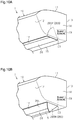
- the distance between an intersection point A, which is where a tangent VL inscribing the tongue 26A of the upper wall 26U orthogonally intersects a flow path formation surface 32X of the support 32 opposing the tongue 26A, and point B, which is the lower end of the indoor unit main body 10, is referred to as distance L.
- the outer diameter of the impeller 25 of the cross-flow fan 23 is referred to as the outer diameter D.
- a ratio (L/D) of the distance L to the outer diameter D is set to less than 0.05.
- Point B is located at the downstream-most portion of the lower wall 26L of the blow-out flow path 26. In the present embodiment, as shown in Fig. 9B , point B is the lowermost point of the flow path formation surface 32X of the support 32.
- the movable side walls 26SM are omitted from the two side walls 26S.
- the movement mechanism 29 includes the flap driving motor 28 (refer to Fig. 3 ).
- the movement mechanism 29 is configured to allow for switching between a stored state, in which the flap 24 forming the blow-out flow path 26 covers the outlet 17, and a projected state, in which the flap 24 projects out of the outlet 17.
- the movement mechanism 29 is in the projected state when an air conditioning operation is performed and in the stored state when an air conditioning operation is stopped.
- the flap 24 is pivoted relative to the support 32 to cover the outlet 17 when an air conditioning operation is stopped.
- the flap 24 is pivoted relative to the support 32 to open the outlet 17 when an air conditioning operation is performed. In the projected state, the flap 24 is faced toward a flow path formation surface 26X of the upper wall 26U.
- the present embodiment has the following advantages.
- the description related with the above embodiments exemplifies, without any intention to limit, applicable forms of an indoor unit of an air conditioner according to the present disclosure.
- the indoor unit of an air conditioner in accordance with the present disclosure is applicable to, for example, modified examples of the above embodiments that are described below and combinations of at least two of the modified examples that do not contradict each other.
- same reference numerals are given to those components that are the same as the corresponding components of the above embodiments. Such components will not be described in detail.
- At least one of the two side walls 26S, the lower wall 26L, and the upper wall 26U of the blow-out flow path 26 may include a movable wall and a fixed wall. More specifically, the indoor unit 1 may be configured in any one of following manners (A1) to (A4).
- the two side walls 26S may be changed to have following configurations in (B1) to (B3).
- the movable side walls 26SM do not have to be configured to be rotated about the rotation axis C2.
- the movable side walls 26SM may be configured so that the distance between the movable side walls 26SM in the sideward direction decreases toward the downstream side in the blow-out flow path 26.
- the movable lower wall 26LM of the lower wall 26L arranged at the distal end of the fixed lower wall 26LF, which is the lower end of the indoor unit main body 10, may be pivotal about a rotation axis C5.
- the flap 24 is pivotally arranged at the distal end of the movable lower wall 26LM.
- the movement mechanism 29 pivots the movable lower wall 26LM to cover the outlet 17 in the stored state. In this case, the outlet 17 is covered by the movable lower wall 26LM and the flap 24.
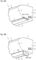
- Fig. 13A when an air conditioning operation is stopped, the movement mechanism 29 pivots the movable lower wall 26LM to cover the outlet 17 in the stored state. In this case, the outlet 17 is covered by the movable lower wall 26LM and the flap 24.
- the movement mechanism 29 pivots and projects the movable lower wall 26LM out of the outlet 17 in the projected state.
- the outlet 17 is not covered by the movable lower wall 26LM or the flap 24.
- the flap driving motor 28 (refer to Fig. 3 ) may freely change a pivotal position of the flap 24 relative to the movable lower wall 26LM.
- the movable upper wall 26UM of the upper wall 26U arranged at the distal end of the fixed upper wall 26UF may be rotatable about a rotation axis C6.
- the movement mechanism 29 pivots the movable upper wall 26UM to cover the outlet 17 in the stored state.
- the flap driving motor 28 moves the flap 24 so that the flap 24 also covers the outlet 17. In this manner, the movable upper wall 26UM and the flap 24 entirely cover the outlet 17.
- the movement mechanism 29 pivots and projects the movable upper wall 26UM out of the outlet 17 in the projected state. In this case, the outlet 17 is not covered by the movable upper wall 26UM or the flap 24.
- the movement mechanism 29 may include a first movement mechanism that moves the movable side walls 26SM and a second movement mechanism that moves the movable lower wall 26LM.
- the first movement mechanism and the second movement mechanism each include a motor and a rotation-linear movement conversion mechanism that converts rotation of the corresponding motor into linear movement. This allows the movable side walls 26SM to be controlled separately from the movable lower wall 26LM.
- the movement mechanism 29 may rotate the flap 24 to decrease the cross-sectional area of the blow-out flow path 26 at a downstream side of the outlet 17.
- the movement mechanism 29 may include a first movement mechanism that moves the movable side walls 26SM, a second movement mechanism that moves the movable lower wall 26LM, and a third movement mechanism that moves the movable upper wall 26UM.
- the first to third movement mechanisms each include a motor and a rotation-linear movement conversion mechanism that converts rotation of the corresponding motor into linear movement. This allows for separate control of the movable side walls 26SM, the movable lower wall 26LM, and the movable upper wall 26UM.
- the movement mechanism 29 may include a first movement mechanism that moves the movable side walls 26SM and the movable lower wall 26LM and a second movement mechanism that moves the movable upper wall 26UM.
- the first and second movement mechanisms each include a motor and a rotation-linear movement conversion mechanism that converts rotation of the corresponding motor into linear movement. This allows the movable side walls 26SM and the movable lower wall 26LM to be controlled separately from the movable upper wall 26UM.
- the movement mechanism 29 may include a first movement mechanism that moves the movable side walls 26SM and a second movement mechanism that moves the movable lower wall 26LM and the movable upper wall 26UM.
- the first and second movement mechanisms each include a motor and a rotation-linear movement conversion mechanism that converts rotation of the corresponding motor into linear movement. This allows the movable side walls 26SM to be controlled separately from the movable lower wall 26LM and the movable upper wall 26UM.
- the movement mechanism 29 may include a first movement mechanism that moves the movable side walls 26SM and the movable upper wall 26UM and a second movement mechanism that moves the movable lower wall 26LM.
- the first and second movement mechanisms each include a motor and a rotation-linear movement conversion mechanism that converts rotation of the corresponding motor into linear movement. This allows the movable side walls 26SM and the movable upper wall 26UM to be controlled separately from the movable lower wall 26LM.
- the blow-out flow path 26 may be formed to project out of the outlet 17 so that the cross-sectional area of the blow-out flow path 26 at a downstream side of the outlet 17 is smaller than the cross-sectional area of the outlet 17.
- at least one of the movable side walls 26SM, the movable lower wall 26LM, and the movable upper wall 26UM is moved by the movement mechanism 29 so that the cross-sectional area surrounded by the movable side walls 26SM, the movable lower wall 26LM, and the movable upper wall 26UM, which are elements of the blow-out flow path 26, is smaller than the cross-sectional area of the outlet 17.
- This increases the velocity in the blow-out flow path 26 at a downstream side and restricts backflow of indoor air from the outlet 17. Thus, surging is even less likely to occur.
- the indoor unit 1 may be changed in any one of following manners (C1) to (C4).
- the movement mechanism 29 may be omitted.
- the elements of the blow-out flow path 26 are constantly in the projected state.
- at least one of the two side walls 26S, the upper wall 26U, and the lower wall 26L is arranged to project out of the outlet 17.
- the two side walls 26S, the upper wall 26U, and the lower wall 26L, which are the elements of the blow-out flow path 26 are arranged to project out of the outlet 17.
- a projection 26P may be arranged on each side wall 26S at a downstream side of the outlet 17 so that the distance between the two side walls 26S in the sideward direction at a downstream side of the outlet 17 in the blow-out flow path 26 is less than the sideward length of the outlet 17.
- each projection 26P has the form of a substantially three-sided pyramid such that the distance between the two side walls 26S (distance between projections 26P in sideward direction) decreases from the upper wall 26U toward the lower wall 26L.
- the projections 26P include surfaces 26PA opposed toward each other in the sideward direction.
- the surfaces 26PA are formed so that the distance between the projections 26P in the sideward direction decreases toward a downstream side in the blow-out flow path 26.
- the projection 26P may have any shape as long as the distance between the two side walls 26S in the blow-out flow path 26 at a downstream side of the outlet 17 is less than the sideward length of the outlet 17.
- the projections 26P may be arranged so that the distance between the two side walls 26S in the sideward direction at a downstream side in the blow-out flow path 26, which is extended by the two side walls 26S projected out of the outlet 17, is constantly smaller than the distance between the two side walls 26S in the sideward direction in the blow-out flow path 26 at the side of the outlet 17 (upstream side).
- the velocity in the blow-out flow path 26 at a downstream side is increased. This restricts backflow of indoor air from the outlet 17 and thus surging is even less likely to occur.
Landscapes
- Engineering & Computer Science (AREA)
- Mechanical Engineering (AREA)
- General Engineering & Computer Science (AREA)
- Chemical & Material Sciences (AREA)
- Combustion & Propulsion (AREA)
- Physics & Mathematics (AREA)
- Geometry (AREA)
- Thermal Sciences (AREA)
- Air-Conditioning Room Units, And Self-Contained Units In General (AREA)
- Air Conditioning Control Device (AREA)
- Structures Of Non-Positive Displacement Pumps (AREA)
- Air Filters, Heat-Exchange Apparatuses, And Housings Of Air-Conditioning Units (AREA)
Applications Claiming Priority (2)
| Application Number | Priority Date | Filing Date | Title |
|---|---|---|---|
| JP2018070196A JP6700621B2 (ja) | 2018-03-30 | 2018-03-30 | 空気調和機の室内機 |
| PCT/JP2019/007258 WO2019187896A1 (ja) | 2018-03-30 | 2019-02-26 | 空気調和機の室内機 |
Publications (3)
| Publication Number | Publication Date |
|---|---|
| EP3779295A1 true EP3779295A1 (de) | 2021-02-17 |
| EP3779295A4 EP3779295A4 (de) | 2021-05-26 |
| EP3779295B1 EP3779295B1 (de) | 2024-12-04 |
Family
ID=68061216
Family Applications (1)
| Application Number | Title | Priority Date | Filing Date |
|---|---|---|---|
| EP19775655.4A Active EP3779295B1 (de) | 2018-03-30 | 2019-02-26 | Innenraumeinheit einer klimaanlage |
Country Status (6)
| Country | Link |
|---|---|
| US (1) | US11073302B2 (de) |
| EP (1) | EP3779295B1 (de) |
| JP (1) | JP6700621B2 (de) |
| CN (1) | CN111919064B (de) |
| AU (1) | AU2019246290B2 (de) |
| WO (1) | WO2019187896A1 (de) |
Families Citing this family (10)
| Publication number | Priority date | Publication date | Assignee | Title |
|---|---|---|---|---|
| EP3505766B1 (de) * | 2016-09-30 | 2021-05-19 | Daikin Industries, Ltd. | Querstromgebläse und innenraumeinheit einer klimaanlage damit |
| JP6843721B2 (ja) * | 2017-09-27 | 2021-03-17 | ダイキン工業株式会社 | 空気調和機 |
| JP6926024B2 (ja) * | 2018-03-30 | 2021-08-25 | ダイキン工業株式会社 | 空気調和機の室内機 |
| EP4194764B1 (de) * | 2020-08-07 | 2025-01-08 | Daikin Industries, Ltd. | Lüftereinheit und damit ausgestattetes luftbehandlungssystem |
| EP4194766B1 (de) | 2020-08-07 | 2025-01-22 | Daikin Industries, Ltd. | Gebläseeinheit und luftbehandlungssystem damit |
| JP7078866B2 (ja) | 2020-08-07 | 2022-06-01 | ダイキン工業株式会社 | ファンユニット |
| WO2022195834A1 (ja) * | 2021-03-19 | 2022-09-22 | 三菱電機株式会社 | 室内機および空気調和装置 |
| WO2022239397A1 (ja) * | 2021-05-14 | 2022-11-17 | ダイキン工業株式会社 | 室内機 |
| CN116182256A (zh) * | 2021-11-26 | 2023-05-30 | 宁波奥克斯电气股份有限公司 | 空调器 |
| CN119123625A (zh) * | 2023-06-12 | 2024-12-13 | 青岛海尔空调器有限总公司 | 处理空调器的蒸发器表面的冷凝水的控制方法及空调器 |
Family Cites Families (18)
| Publication number | Priority date | Publication date | Assignee | Title |
|---|---|---|---|---|
| JPH05272799A (ja) | 1992-03-30 | 1993-10-19 | Toshiba Corp | 空気調和装置の室内ユニット |
| AU767078B2 (en) * | 2000-09-29 | 2003-10-30 | Mitsubishi Denki Kabushiki Kaisha | Air conditioner |
| JP4580377B2 (ja) * | 2006-11-22 | 2010-11-10 | シャープ株式会社 | 空気調和機 |
| JP2008190813A (ja) * | 2007-02-07 | 2008-08-21 | Hitachi Appliances Inc | 静電霧化装置を搭載した空気調和機 |
| JP2009121731A (ja) | 2007-11-14 | 2009-06-04 | Sharp Corp | 空気調和機 |
| JP4947227B1 (ja) * | 2011-06-30 | 2012-06-06 | パナソニック株式会社 | 空気調和機 |
| JP5338895B2 (ja) * | 2011-12-28 | 2013-11-13 | ダイキン工業株式会社 | 空調室内機 |
| JP5803869B2 (ja) * | 2012-09-28 | 2015-11-04 | ダイキン工業株式会社 | 空調室内機 |
| JP6340597B2 (ja) * | 2013-06-12 | 2018-06-13 | パナソニックIpマネジメント株式会社 | 空気調和機 |
| JP5413535B2 (ja) * | 2013-09-09 | 2014-02-12 | ダイキン工業株式会社 | 空調室内機 |
| JP2015055419A (ja) * | 2013-09-12 | 2015-03-23 | パナソニック株式会社 | 空気調和機 |
| JP6774161B2 (ja) * | 2014-08-07 | 2020-10-21 | 東芝ライフスタイル株式会社 | 空気調和機の室内機 |
| WO2016067408A1 (ja) * | 2014-10-30 | 2016-05-06 | 三菱電機株式会社 | 空気調和機 |
| JP6299716B2 (ja) * | 2015-09-30 | 2018-03-28 | ダイキン工業株式会社 | 空調室内機 |
| JP2018025344A (ja) * | 2016-08-09 | 2018-02-15 | パナソニックIpマネジメント株式会社 | 空気調和機 |
| FR3065791A1 (fr) * | 2017-05-01 | 2018-11-02 | Eric Convoi Nelson | Deflecteur d'air, recyclant, pour climatiseurs de types mural et plafonnier (unites interieures). |
| CN107120730B (zh) | 2017-06-09 | 2020-02-04 | 青岛海尔空调器有限总公司 | 壁挂式空调室内机及其控制方法 |
| US11573029B2 (en) * | 2018-06-18 | 2023-02-07 | Johnson Controls Tyco IP Holdings LLP | Collapsible vent hood for HVAC unit |
-
2018
- 2018-03-30 JP JP2018070196A patent/JP6700621B2/ja active Active
-
2019
- 2019-02-26 CN CN201980022147.1A patent/CN111919064B/zh active Active
- 2019-02-26 US US17/041,966 patent/US11073302B2/en active Active
- 2019-02-26 WO PCT/JP2019/007258 patent/WO2019187896A1/ja not_active Ceased
- 2019-02-26 AU AU2019246290A patent/AU2019246290B2/en active Active
- 2019-02-26 EP EP19775655.4A patent/EP3779295B1/de active Active
Also Published As
| Publication number | Publication date |
|---|---|
| EP3779295A4 (de) | 2021-05-26 |
| EP3779295B1 (de) | 2024-12-04 |
| CN111919064B (zh) | 2021-08-10 |
| JP2019178852A (ja) | 2019-10-17 |
| JP6700621B2 (ja) | 2020-05-27 |
| US20210048220A1 (en) | 2021-02-18 |
| US11073302B2 (en) | 2021-07-27 |
| AU2019246290B2 (en) | 2020-11-05 |
| WO2019187896A1 (ja) | 2019-10-03 |
| AU2019246290A1 (en) | 2020-10-29 |
| CN111919064A (zh) | 2020-11-10 |
Similar Documents
| Publication | Publication Date | Title |
|---|---|---|
| EP3779295B1 (de) | Innenraumeinheit einer klimaanlage | |
| TWI706114B (zh) | 室內機及空調裝置 | |
| US11002451B2 (en) | Air conditioner | |
| EP3460254B1 (de) | Klimaanlage | |
| EP3779296B1 (de) | Innenraumeinheit einer klimaanlage | |
| JP5186166B2 (ja) | 空気調和機 | |
| CN204786792U (zh) | 空调室内机 | |
| EP3578897B1 (de) | Klimaanlage | |
| EP3412983B1 (de) | Innenraumeinheit für klimaanlagen | |
| CN114391079A (zh) | 空调室内机 | |
| CN103261808B (zh) | 空调机 | |
| JP6787942B2 (ja) | 空気調和機の室内機 | |
| JP2685139B2 (ja) | 空気調和機 | |
| CN107741058A (zh) | 壁挂式空调室内机及具有其的空调器 | |
| EP4310404A1 (de) | Innenraumeinheit und klimaanlagenvorrichtung | |
| JPH0979646A (ja) | 空気調和装置 | |
| JP7258099B2 (ja) | 空気調和装置及び冷凍サイクル装置 | |
| EP4509765A1 (de) | Klimaanlage mit einer an der unterklappe vorgesehenen hilfsklappe | |
| JP2018138854A (ja) | 送風装置 | |
| CN112393327A (zh) | 壁挂式空调室内机及空调器 | |
| JPH04136449U (ja) | 空気調和装置 | |
| HK40004784B (zh) | 室内机及空调装置 |
Legal Events
| Date | Code | Title | Description |
|---|---|---|---|
| STAA | Information on the status of an ep patent application or granted ep patent |
Free format text: STATUS: THE INTERNATIONAL PUBLICATION HAS BEEN MADE |
|
| PUAI | Public reference made under article 153(3) epc to a published international application that has entered the european phase |
Free format text: ORIGINAL CODE: 0009012 |
|
| STAA | Information on the status of an ep patent application or granted ep patent |
Free format text: STATUS: REQUEST FOR EXAMINATION WAS MADE |
|
| 17P | Request for examination filed |
Effective date: 20201002 |
|
| AK | Designated contracting states |
Kind code of ref document: A1 Designated state(s): AL AT BE BG CH CY CZ DE DK EE ES FI FR GB GR HR HU IE IS IT LI LT LU LV MC MK MT NL NO PL PT RO RS SE SI SK SM TR |
|
| AX | Request for extension of the european patent |
Extension state: BA ME |
|
| A4 | Supplementary search report drawn up and despatched |
Effective date: 20210423 |
|
| RIC1 | Information provided on ipc code assigned before grant |
Ipc: F24F 1/0025 20190101AFI20210419BHEP Ipc: F24F 13/20 20060101ALI20210419BHEP Ipc: F24F 1/0011 20190101ALI20210419BHEP Ipc: F24F 13/08 20060101ALI20210419BHEP Ipc: F24F 1/0057 20190101ALI20210419BHEP Ipc: F24F 13/10 20060101ALI20210419BHEP Ipc: F04D 17/04 20060101ALI20210419BHEP Ipc: F04D 29/66 20060101ALI20210419BHEP Ipc: F24F 13/24 20060101ALN20210419BHEP |
|
| DAV | Request for validation of the european patent (deleted) | ||
| DAX | Request for extension of the european patent (deleted) | ||
| STAA | Information on the status of an ep patent application or granted ep patent |
Free format text: STATUS: EXAMINATION IS IN PROGRESS |
|
| 17Q | First examination report despatched |
Effective date: 20220118 |
|
| RAP3 | Party data changed (applicant data changed or rights of an application transferred) |
Owner name: DAIKIN INDUSTRIES, LTD. |
|
| P01 | Opt-out of the competence of the unified patent court (upc) registered |
Effective date: 20230525 |
|
| GRAP | Despatch of communication of intention to grant a patent |
Free format text: ORIGINAL CODE: EPIDOSNIGR1 |
|
| STAA | Information on the status of an ep patent application or granted ep patent |
Free format text: STATUS: GRANT OF PATENT IS INTENDED |
|
| RIC1 | Information provided on ipc code assigned before grant |
Ipc: F24F 13/24 20060101ALN20240719BHEP Ipc: F04D 29/58 20060101ALI20240719BHEP Ipc: F04D 29/46 20060101ALI20240719BHEP Ipc: F04D 27/00 20060101ALI20240719BHEP Ipc: F04D 25/14 20060101ALI20240719BHEP Ipc: F04D 29/66 20060101ALI20240719BHEP Ipc: F04D 17/04 20060101ALI20240719BHEP Ipc: F24F 13/10 20060101ALI20240719BHEP Ipc: F24F 1/0057 20190101ALI20240719BHEP Ipc: F24F 13/08 20060101ALI20240719BHEP Ipc: F24F 1/0011 20190101ALI20240719BHEP Ipc: F24F 13/20 20060101ALI20240719BHEP Ipc: F24F 1/0025 20190101AFI20240719BHEP |
|
| INTG | Intention to grant announced |
Effective date: 20240806 |
|
| GRAS | Grant fee paid |
Free format text: ORIGINAL CODE: EPIDOSNIGR3 |
|
| GRAA | (expected) grant |
Free format text: ORIGINAL CODE: 0009210 |
|
| STAA | Information on the status of an ep patent application or granted ep patent |
Free format text: STATUS: THE PATENT HAS BEEN GRANTED |
|
| AK | Designated contracting states |
Kind code of ref document: B1 Designated state(s): AL AT BE BG CH CY CZ DE DK EE ES FI FR GB GR HR HU IE IS IT LI LT LU LV MC MK MT NL NO PL PT RO RS SE SI SK SM TR |
|
| REG | Reference to a national code |
Ref country code: CH Ref legal event code: EP |
|
| REG | Reference to a national code |
Ref country code: DE Ref legal event code: R096 Ref document number: 602019063002 Country of ref document: DE |
|
| REG | Reference to a national code |
Ref country code: IE Ref legal event code: FG4D |
|
| REG | Reference to a national code |
Ref country code: LT Ref legal event code: MG9D |
|
| REG | Reference to a national code |
Ref country code: NL Ref legal event code: MP Effective date: 20241204 |
|
| PG25 | Lapsed in a contracting state [announced via postgrant information from national office to epo] |
Ref country code: HR Free format text: LAPSE BECAUSE OF FAILURE TO SUBMIT A TRANSLATION OF THE DESCRIPTION OR TO PAY THE FEE WITHIN THE PRESCRIBED TIME-LIMIT Effective date: 20241204 |
|
| PG25 | Lapsed in a contracting state [announced via postgrant information from national office to epo] |
Ref country code: FI Free format text: LAPSE BECAUSE OF FAILURE TO SUBMIT A TRANSLATION OF THE DESCRIPTION OR TO PAY THE FEE WITHIN THE PRESCRIBED TIME-LIMIT Effective date: 20241204 |
|
| PG25 | Lapsed in a contracting state [announced via postgrant information from national office to epo] |
Ref country code: BG Free format text: LAPSE BECAUSE OF FAILURE TO SUBMIT A TRANSLATION OF THE DESCRIPTION OR TO PAY THE FEE WITHIN THE PRESCRIBED TIME-LIMIT Effective date: 20241204 |
|
| PG25 | Lapsed in a contracting state [announced via postgrant information from national office to epo] |
Ref country code: ES Free format text: LAPSE BECAUSE OF FAILURE TO SUBMIT A TRANSLATION OF THE DESCRIPTION OR TO PAY THE FEE WITHIN THE PRESCRIBED TIME-LIMIT Effective date: 20241204 |
|
| PG25 | Lapsed in a contracting state [announced via postgrant information from national office to epo] |
Ref country code: NO Free format text: LAPSE BECAUSE OF FAILURE TO SUBMIT A TRANSLATION OF THE DESCRIPTION OR TO PAY THE FEE WITHIN THE PRESCRIBED TIME-LIMIT Effective date: 20250304 |
|
| PG25 | Lapsed in a contracting state [announced via postgrant information from national office to epo] |
Ref country code: GR Free format text: LAPSE BECAUSE OF FAILURE TO SUBMIT A TRANSLATION OF THE DESCRIPTION OR TO PAY THE FEE WITHIN THE PRESCRIBED TIME-LIMIT Effective date: 20250305 Ref country code: LV Free format text: LAPSE BECAUSE OF FAILURE TO SUBMIT A TRANSLATION OF THE DESCRIPTION OR TO PAY THE FEE WITHIN THE PRESCRIBED TIME-LIMIT Effective date: 20241204 |
|
| PG25 | Lapsed in a contracting state [announced via postgrant information from national office to epo] |
Ref country code: RS Free format text: LAPSE BECAUSE OF FAILURE TO SUBMIT A TRANSLATION OF THE DESCRIPTION OR TO PAY THE FEE WITHIN THE PRESCRIBED TIME-LIMIT Effective date: 20250304 |
|
| PG25 | Lapsed in a contracting state [announced via postgrant information from national office to epo] |
Ref country code: NL Free format text: LAPSE BECAUSE OF FAILURE TO SUBMIT A TRANSLATION OF THE DESCRIPTION OR TO PAY THE FEE WITHIN THE PRESCRIBED TIME-LIMIT Effective date: 20241204 |
|
| REG | Reference to a national code |
Ref country code: AT Ref legal event code: MK05 Ref document number: 1748553 Country of ref document: AT Kind code of ref document: T Effective date: 20241204 |
|
| PG25 | Lapsed in a contracting state [announced via postgrant information from national office to epo] |
Ref country code: SM Free format text: LAPSE BECAUSE OF FAILURE TO SUBMIT A TRANSLATION OF THE DESCRIPTION OR TO PAY THE FEE WITHIN THE PRESCRIBED TIME-LIMIT Effective date: 20241204 |
|
| PG25 | Lapsed in a contracting state [announced via postgrant information from national office to epo] |
Ref country code: PL Free format text: LAPSE BECAUSE OF FAILURE TO SUBMIT A TRANSLATION OF THE DESCRIPTION OR TO PAY THE FEE WITHIN THE PRESCRIBED TIME-LIMIT Effective date: 20241204 |
|
| PG25 | Lapsed in a contracting state [announced via postgrant information from national office to epo] |
Ref country code: IS Free format text: LAPSE BECAUSE OF FAILURE TO SUBMIT A TRANSLATION OF THE DESCRIPTION OR TO PAY THE FEE WITHIN THE PRESCRIBED TIME-LIMIT Effective date: 20250404 |
|
| PG25 | Lapsed in a contracting state [announced via postgrant information from national office to epo] |
Ref country code: PT Free format text: LAPSE BECAUSE OF FAILURE TO SUBMIT A TRANSLATION OF THE DESCRIPTION OR TO PAY THE FEE WITHIN THE PRESCRIBED TIME-LIMIT Effective date: 20250404 |
|
| PG25 | Lapsed in a contracting state [announced via postgrant information from national office to epo] |
Ref country code: EE Free format text: LAPSE BECAUSE OF FAILURE TO SUBMIT A TRANSLATION OF THE DESCRIPTION OR TO PAY THE FEE WITHIN THE PRESCRIBED TIME-LIMIT Effective date: 20241204 |
|
| PG25 | Lapsed in a contracting state [announced via postgrant information from national office to epo] |
Ref country code: RO Free format text: LAPSE BECAUSE OF FAILURE TO SUBMIT A TRANSLATION OF THE DESCRIPTION OR TO PAY THE FEE WITHIN THE PRESCRIBED TIME-LIMIT Effective date: 20241204 Ref country code: AT Free format text: LAPSE BECAUSE OF FAILURE TO SUBMIT A TRANSLATION OF THE DESCRIPTION OR TO PAY THE FEE WITHIN THE PRESCRIBED TIME-LIMIT Effective date: 20241204 |
|
| PG25 | Lapsed in a contracting state [announced via postgrant information from national office to epo] |
Ref country code: SK Free format text: LAPSE BECAUSE OF FAILURE TO SUBMIT A TRANSLATION OF THE DESCRIPTION OR TO PAY THE FEE WITHIN THE PRESCRIBED TIME-LIMIT Effective date: 20241204 |
|
| PG25 | Lapsed in a contracting state [announced via postgrant information from national office to epo] |
Ref country code: CZ Free format text: LAPSE BECAUSE OF FAILURE TO SUBMIT A TRANSLATION OF THE DESCRIPTION OR TO PAY THE FEE WITHIN THE PRESCRIBED TIME-LIMIT Effective date: 20241204 |
|
| PG25 | Lapsed in a contracting state [announced via postgrant information from national office to epo] |
Ref country code: IT Free format text: LAPSE BECAUSE OF FAILURE TO SUBMIT A TRANSLATION OF THE DESCRIPTION OR TO PAY THE FEE WITHIN THE PRESCRIBED TIME-LIMIT Effective date: 20241204 |
|
| REG | Reference to a national code |
Ref country code: DE Ref legal event code: R097 Ref document number: 602019063002 Country of ref document: DE |
|
| PG25 | Lapsed in a contracting state [announced via postgrant information from national office to epo] |
Ref country code: SE Free format text: LAPSE BECAUSE OF FAILURE TO SUBMIT A TRANSLATION OF THE DESCRIPTION OR TO PAY THE FEE WITHIN THE PRESCRIBED TIME-LIMIT Effective date: 20241204 |
|
| PG25 | Lapsed in a contracting state [announced via postgrant information from national office to epo] |
Ref country code: MC Free format text: LAPSE BECAUSE OF FAILURE TO SUBMIT A TRANSLATION OF THE DESCRIPTION OR TO PAY THE FEE WITHIN THE PRESCRIBED TIME-LIMIT Effective date: 20241204 |
|
| REG | Reference to a national code |
Ref country code: CH Ref legal event code: PL |
|
| PG25 | Lapsed in a contracting state [announced via postgrant information from national office to epo] |
Ref country code: DK Free format text: LAPSE BECAUSE OF FAILURE TO SUBMIT A TRANSLATION OF THE DESCRIPTION OR TO PAY THE FEE WITHIN THE PRESCRIBED TIME-LIMIT Effective date: 20241204 |
|
| PLBE | No opposition filed within time limit |
Free format text: ORIGINAL CODE: 0009261 |
|
| STAA | Information on the status of an ep patent application or granted ep patent |
Free format text: STATUS: NO OPPOSITION FILED WITHIN TIME LIMIT |
|
| PG25 | Lapsed in a contracting state [announced via postgrant information from national office to epo] |
Ref country code: LU Free format text: LAPSE BECAUSE OF NON-PAYMENT OF DUE FEES Effective date: 20250226 |
|
| PG25 | Lapsed in a contracting state [announced via postgrant information from national office to epo] |
Ref country code: CH Free format text: LAPSE BECAUSE OF NON-PAYMENT OF DUE FEES Effective date: 20250228 |
|
| 26N | No opposition filed |
Effective date: 20250905 |
|
| REG | Reference to a national code |
Ref country code: BE Ref legal event code: MM Effective date: 20250228 |
|
| PG25 | Lapsed in a contracting state [announced via postgrant information from national office to epo] |
Ref country code: BE Free format text: LAPSE BECAUSE OF NON-PAYMENT OF DUE FEES Effective date: 20250228 |
|
| PG25 | Lapsed in a contracting state [announced via postgrant information from national office to epo] |
Ref country code: IE Free format text: LAPSE BECAUSE OF NON-PAYMENT OF DUE FEES Effective date: 20250226 |
|
| PGFP | Annual fee paid to national office [announced via postgrant information from national office to epo] |
Ref country code: GB Payment date: 20260220 Year of fee payment: 8 |
|
| PGFP | Annual fee paid to national office [announced via postgrant information from national office to epo] |
Ref country code: DE Payment date: 20260218 Year of fee payment: 8 |
|
| PGFP | Annual fee paid to national office [announced via postgrant information from national office to epo] |
Ref country code: FR Payment date: 20260218 Year of fee payment: 8 |