EP3779312A1 - Structure de sortie d'air et climatiseur pourvu de celle-ci - Google Patents
Structure de sortie d'air et climatiseur pourvu de celle-ci Download PDFInfo
- Publication number
- EP3779312A1 EP3779312A1 EP18917904.7A EP18917904A EP3779312A1 EP 3779312 A1 EP3779312 A1 EP 3779312A1 EP 18917904 A EP18917904 A EP 18917904A EP 3779312 A1 EP3779312 A1 EP 3779312A1
- Authority
- EP
- European Patent Office
- Prior art keywords
- air outlet
- air
- outer edge
- air deflector
- flow guiding
- Prior art date
- Legal status (The legal status is an assumption and is not a legal conclusion. Google has not performed a legal analysis and makes no representation as to the accuracy of the status listed.)
- Ceased
Links
Images


Classifications
-
- F—MECHANICAL ENGINEERING; LIGHTING; HEATING; WEAPONS; BLASTING
- F24—HEATING; RANGES; VENTILATING
- F24F—AIR-CONDITIONING; AIR-HUMIDIFICATION; VENTILATION; USE OF AIR CURRENTS FOR SCREENING
- F24F1/00—Room units for air-conditioning, e.g. separate or self-contained units or units receiving primary air from a central station
- F24F1/0007—Indoor units, e.g. fan coil units
- F24F1/0011—Indoor units, e.g. fan coil units characterised by air outlets
-
- F—MECHANICAL ENGINEERING; LIGHTING; HEATING; WEAPONS; BLASTING
- F24—HEATING; RANGES; VENTILATING
- F24F—AIR-CONDITIONING; AIR-HUMIDIFICATION; VENTILATION; USE OF AIR CURRENTS FOR SCREENING
- F24F13/00—Details common to, or for air-conditioning, air-humidification, ventilation or use of air currents for screening
- F24F13/08—Air-flow control members, e.g. louvres, grilles, flaps or guide plates
- F24F13/10—Air-flow control members, e.g. louvres, grilles, flaps or guide plates movable, e.g. dampers
- F24F13/14—Air-flow control members, e.g. louvres, grilles, flaps or guide plates movable, e.g. dampers built up of tilting members, e.g. louvre
- F24F13/1413—Air-flow control members, e.g. louvres, grilles, flaps or guide plates movable, e.g. dampers built up of tilting members, e.g. louvre using more than one tilting member, e.g. with several pivoting blades
-
- F—MECHANICAL ENGINEERING; LIGHTING; HEATING; WEAPONS; BLASTING
- F24—HEATING; RANGES; VENTILATING
- F24F—AIR-CONDITIONING; AIR-HUMIDIFICATION; VENTILATION; USE OF AIR CURRENTS FOR SCREENING
- F24F1/00—Room units for air-conditioning, e.g. separate or self-contained units or units receiving primary air from a central station
- F24F1/0003—Room units for air-conditioning, e.g. separate or self-contained units or units receiving primary air from a central station characterised by a split arrangement, wherein parts of the air-conditioning system, e.g. evaporator and condenser, are in separately located units
-
- F—MECHANICAL ENGINEERING; LIGHTING; HEATING; WEAPONS; BLASTING
- F24—HEATING; RANGES; VENTILATING
- F24F—AIR-CONDITIONING; AIR-HUMIDIFICATION; VENTILATION; USE OF AIR CURRENTS FOR SCREENING
- F24F13/00—Details common to, or for air-conditioning, air-humidification, ventilation or use of air currents for screening
- F24F13/08—Air-flow control members, e.g. louvres, grilles, flaps or guide plates
-
- F—MECHANICAL ENGINEERING; LIGHTING; HEATING; WEAPONS; BLASTING
- F24—HEATING; RANGES; VENTILATING
- F24F—AIR-CONDITIONING; AIR-HUMIDIFICATION; VENTILATION; USE OF AIR CURRENTS FOR SCREENING
- F24F13/00—Details common to, or for air-conditioning, air-humidification, ventilation or use of air currents for screening
- F24F13/22—Means for preventing condensation or evacuating condensate
- F24F13/222—Means for preventing condensation or evacuating condensate for evacuating condensate
-
- F—MECHANICAL ENGINEERING; LIGHTING; HEATING; WEAPONS; BLASTING
- F24—HEATING; RANGES; VENTILATING
- F24F—AIR-CONDITIONING; AIR-HUMIDIFICATION; VENTILATION; USE OF AIR CURRENTS FOR SCREENING
- F24F1/00—Room units for air-conditioning, e.g. separate or self-contained units or units receiving primary air from a central station
- F24F1/0007—Indoor units, e.g. fan coil units
- F24F1/0043—Indoor units, e.g. fan coil units characterised by mounting arrangements
- F24F1/0057—Indoor units, e.g. fan coil units characterised by mounting arrangements mounted in or on a wall
-
- F—MECHANICAL ENGINEERING; LIGHTING; HEATING; WEAPONS; BLASTING
- F24—HEATING; RANGES; VENTILATING
- F24F—AIR-CONDITIONING; AIR-HUMIDIFICATION; VENTILATION; USE OF AIR CURRENTS FOR SCREENING
- F24F13/00—Details common to, or for air-conditioning, air-humidification, ventilation or use of air currents for screening
- F24F13/22—Means for preventing condensation or evacuating condensate
-
- F—MECHANICAL ENGINEERING; LIGHTING; HEATING; WEAPONS; BLASTING
- F24—HEATING; RANGES; VENTILATING
- F24F—AIR-CONDITIONING; AIR-HUMIDIFICATION; VENTILATION; USE OF AIR CURRENTS FOR SCREENING
- F24F13/00—Details common to, or for air-conditioning, air-humidification, ventilation or use of air currents for screening
- F24F13/22—Means for preventing condensation or evacuating condensate
- F24F2013/221—Means for preventing condensation or evacuating condensate to avoid the formation of condensate, e.g. dew
Definitions
- the present invention relates to the field of air conditioner, and particularly, to an air outlet structure and an air conditioner having the same.
- the air deflectors are provided on a panel body through an air deflector support.
- the air deflectors rotate relative to the air deflector support to achieve air swing at an air outlet.
- the existing air deflector supports are all provided at a middle position of the air outlet.
- the main objective of the present invention is to provide an air outlet structure and an air conditioner having the same to solve a problem that the air deflector of the air outlet structure in the prior art is not easily opened or closed.
- an air outlet structure includes: an air outlet portion body having an air outlet; an air deflector support connected to the air outlet portion body and provided at a lower portion of the air outlet; and an air deflector rotatably provided on the air deflector support.
- the air outlet portion body is provided with a flow guiding channel; the flow guiding channel is in communication with the air outlet; and the air deflector support is connected to a channel wall of the flow guiding channel.
- the flow guiding channel is a groove.
- a cross section of the flow guiding channel is trapezoidal, and the flow guiding channel gradually shrinks in a flow direction of an air current.
- a second preset included angle b is formed between two adjacent side walls of the flow guiding channel, and 15° ⁇ b ⁇ 85° is satisfied.
- the air deflector support includes: a support body connected to the air deflector, and a flow guiding portion provided on the support body; the flow guiding portion includes at least one of a convex portion or a concave portion.
- the flow guiding portion is provided on a lower edge of the support body.
- the plurality of flow guiding portions are provided at intervals along an outer edge of the support body.
- the flow guiding portion is a groove, and a cross-section of the groove is trapezoidal.
- the flow guiding portion includes a bottom wall, a first side wall, and a second side wall; the bottom wall is disposed between the first side wall and the second side wall; and a curved transition is formed between the bottom wall and the first side wall, and/or, a curved transition is formed between the bottom wall and the second side wall.
- a first preset included angle a is formed between a plane where the bottom wall is located and a horizontal plane, and the first preset included angle a is an acute angle.
- the support body includes: a first outer edge, and a second outer edge joined to the first outer edge; in a flow direction of an air current, the air current passes through the first outer edge and the second outer edge in sequence; and at least a part of the second outer edge is provided with the flow guiding portion.
- the support body further includes a third outer edge connected to the second outer edge; the second outer edge is located between the first outer edge and the third outer edge; and the third outer edge is provided with the flow guiding portion.
- the third outer edge is inclined downwards relative to the first outer edge.
- the air outlet portion body includes a bottom shell and a panel body; and the air deflector support is provided on the panel body or on the bottom shell.
- the air outlet structure further includes an upper air deflector support connected to the air outlet portion body and provided on an upper portion of the air outlet, and an upper air deflector rotatably provided on the upper air deflector support.
- the air deflector has a first position and a second position
- the upper air deflector has a third position and a fourth position; when the air deflector is located at the first position, and when the upper air deflector is located at the third position, the air deflector and the upper air deflector are configured to block the air outlet; and when the air deflector is located at the second position, and when the upper air deflector is located at the fourth position, the air deflector and the upper air deflector are configured enable the air outlet to be exposed.
- the air deflector is configured to move from the first position to the second position in a first direction; the upper air deflector is configured to move from the third position to the fourth position in a second direction; and the first direction is a clockwise direction, and the second direction is a counterclockwise direction; or the first direction is a counterclockwise direction, and the second direction is a clockwise direction.
- an air conditioner is provided and includes an air outlet structure, and the air outlet structure is any one of the air outlet structures above.
- the air deflector support is provided at the lower portion of the air outlet, and the air deflector is rotatably provided on the air deflector support, thereby facilitating the opening and closing of the air deflector; and during the opening and closing of the air deflector, the problem of interference does not occur.
- the air outlet portion body has an air outlet, and the air deflector support is connected to the air outlet portion body.
- the air deflector support is provided at the lower portion of the air outlet, so that the problem of interference does not occur during the opening or closing of the air deflector, thereby solving the problem of the air outlet structure in the prior art that the air deflector is not easily opened or closed.
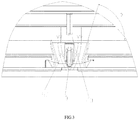
- the air outlet structure includes: an air outlet portion body having an air outlet 40, an air deflector support connected to the air outlet portion body and provided at a lower portion of the air outlet 40, and an air deflector 20 rotatably provided on the air deflector support.
- the air deflector support is provided at the lower portion of the air outlet 40, and the air deflector 20 is rotatably provided on the air deflector support, thereby facilitating opening and closing of the air deflector 20. In a process of opening and closing the air deflector 20, a problem of interference does not occur.
- the air outlet portion body has an air outlet 40, and the air deflector support is connected to the air outlet portion body.
- the air deflector support is provided with at the lower portion of the air outlet 40, so that the problem of interference does not occur in the process of opening or closing the air deflector 20, thereby solving the problem of the air outlet structure in the prior art that the air deflector is not easily opened or closed.
- the air deflector 20 is a lower air deflector of the air outlet structure.
- the air deflector support is provided at the lower portion of the air outlet 40, that is, the air deflector support is located at a position inside the air outlet 40 and adjacent to a lower edge of the air outlet 40, which means that the air deflector support is relatively close to the outside space.
- the air deflector support is provided at the lower portion of the air outlet 40, that is, the air deflector support is located at a position outside the air outlet 40 and adjacent to the lower edge of the air outlet 40.
- the air outlet portion body is provided with a flow guiding channel 80, which is in communication with the air outlet 40, and the air deflector support is connected to a channel wall of the flow guiding channel 80.
- the air outlet portion body is provided with the flow guiding channel 80; the flow guiding channel 80 is in communication with the air outlet 40; and the air deflector support is connected to the channel wall of the flow guiding channel 80.
- the air current can be guided to blow onto the air deflector support through the flow guiding channel 80, thus a temperature difference between the air deflector support and the outside environment is reduced, and the generation of condensation water is prevented.
- the flow guiding channel 80 is provided inside the air outlet 40.
- the flow guiding channel 80 is a groove.
- a cross section of the flow guiding channel 80 is trapezoidal, and the flow guiding channel 80 gradually shrinks in a flow direction of the air current.
- a second preset included angle b is formed between two adjacent side walls of the flow guiding channel 80, where 15° ⁇ b ⁇ 85°.
- the flow guiding channel 80 is an inverted-" A"-shaped air guide groove, and the air deflector support is provided at a middle position of the flow guiding channel 80.
- a bevel edge of the inverted-" "-shaped air guide groove forms an angle of about 10° to 30° relative to a vertical position of a lower edge of the air outlet.
- a width of a lower end of the groove ranges from 8mm to 15mm, and a depth of the groove ranges from 1mm to 3mm.
- the air deflector support includes: a support body 10 connected to the air deflector 20, and a flow guiding portion 30 provided on the support body 10.
- the flow guiding portion 30 comprises at least one of a convex portion or a concave portion.
- the support body 10 is provided with the flow guiding portion 30, which can increase an adhesion area of the condensation water, thereby preventing a large amount of condensation water from falling.
- the support body 10 is configured to be connected to the air deflector 20, and the flow guiding portion 30 is at least one of the convex portion or the concave portion.
- the support body 10 is provided with the flow guiding portion 30, which can increase the adhesion area of the condensation water, prevent condensation water from gathering greatly, and reduce an amount of the fallen condensation water, thereby solving the problem that the condensation water generated by the air deflector support in the prior art falls easily.
- the flow guiding portion 30 is provided on the outer edge of the support body 10.
- the flow guiding portion 30 is provided on the lower edge of the support body 10.
- the plurality of flow guiding portions 30 are provided at intervals on a part of the outer edge of the support body 10.
- the flow guiding portion 30 is provided on the outer edge of the support body 10.
- the flow guiding portion 30 is a groove, and the groove is a rectangular groove or a V-shaped groove.
- the flow guiding portion 30 is the groove, that is, the groove is provided on the outer edge surface of the support body 10.
- the groove is the rectangular groove or the V-shaped groove.
- the flow guiding portion 30 is a groove, and a cross section of the groove is trapezoidal.
- the flow guiding portion 30 includes a bottom wall 31, a first side wall 32, and a second side wall 33.
- the bottom wall 31 is disposed between the first side wall 32 and the second side wall 33.
- a curved transition is formed between the bottom wall 31 and the first side wall 32, and/or, a curved transition is formed between the bottom wall 31 and the second side wall 33.
- the cross section of the flow guiding portion 30 is trapezoidal, that is, the flow guiding portion 30 is a trapezoidal groove.
- the flow guiding portion 30 includes the bottom wall 31, the first side wall 32, and the second side wall 33.
- the bottom wall 31 is disposed between the first side wall 32 and the second side wall 33.
- the bottom wall 31, the first side wall 32, and the second side wall 33 are three groove surfaces of the trapezoidal groove.
- the condensation water can be prevented from gathering at a certain position and falling down.
- a first preset included angle a is formed between a plane where the bottom wall 31 is located and a horizontal plane, and the first preset included angle a is an acute angle.
- the first preset included angle a is formed between the plane where the bottom wall 31 is located and the horizontal plane, where the horizontal plane is defined relative to an installation position of the air deflector support. That is, when the air deflector support is installed in position, the bottom wall 31 has a certain inclination relative to the horizontal plane, and a configuration of the inclination can also make the adhesion area of the condensation water to be increased.
- the support body 10 includes a first outer edge 11 and a second outer edge 12.
- the second outer edge 12 is joined to the first outer edge 11. In the flow direction of the air current, the air current passes through the first outer edge 11 and the second outer edge 12 in sequence. At least a part of the second outer edge 12 is provided with the flow guiding portion 30.
- the support body 10 includes the first outer edge 11 and the second outer edge 12.
- the second outer edge 12 is joined to the first outer edge 11.
- the air current passes through the first outer edge 11 and the second outer edge 12 in sequence, that is, the second outer edge 12 is closer to the outside space, and the condensation water is easily formed thereon. Therefore at least the part of the second outer edge 12 is provided with the flow guiding portion 30 to prevent the condensation water from gathering.
- the support body 10 further includes a third outer edge 13 joined to the second outer edge 12.
- the second outer edge 12 is located between the first outer edge 11 and the third outer edge 13.
- the third outer edge 13 is provided with the flow guiding portion 30.
- the third outer edge 13 is located in the lower portion of the support body 10, that is, compared with the first outer edge 11, the third outer edge 13 is closer to the lower edge of the air outlet 40 and closer to the outside space.
- the support body 10 includes the first outer edge 11, the second outer edge 12, and the third outer edge 13.
- the second outer edge 12 is located between the first outer edge 11 and the third outer edge 13.
- the air current can pass through the first outer edge 11, the second outer edge 12, and the third outer edge 13 in sequence. That is, compared with the second outer edge 12, the third outer edge 13 is closer to the outside space, and the air current finally blows to the third outer edge 13, or the air current is unable to directly blow to the third outer edge 13. Therefore, by providing the flow guiding portion 30 on the third outer edge 13, the adhesion area of the condensation water on the third outer edge 13 is increased.
- the air current can blow to the third outer edge 13 through the second outer edge 12.
- the third outer edge 13 is curved surface, and a curved transition is formed between the second outer edge 12 and the third outer edge 13.
- the third outer edge 13 is inclined downwards relative to the first outer edge 11.
- the first outer edge 11 is a flat surface
- the second outer edge 12 is a circular-arc-shaped surface.
- the third outer edge 13 is a curved surface.
- the lower surface or the front end surface of the support body 10 is provided with the flow guiding portion 30.
- the flow guiding portion 30 has a tooth-shaped groove structure such as rectangular tooth, V-shaped tooth, concave and convex groove/dot, sunned print, and a grid-shaped tooth, etc.
- a width of the tooth ranges from 1mm to 2mm, and a height of the tooth ranges from 1mm to 2mm.
- the flow guiding portion 30 By configuring the flow guiding portion 30 with a tooth-shaped groove surface, on one hand, some condensation water can be collected in the tooth-shaped groove, which increases the water collection or water storage capacity of the lower surface. On the other hand, an area of the lower surface of the support body 10 is increased, thereby increasing the adhesion area of the condensation water. Even if some condensation water is generated on the lower surface of the support, the condensation water delays falling.
- a length extending direction of the support body 10 is inclined downward, so that the tooth-shaped surface of the lower surface forms an angle between 3° and 12° relative to the horizontal plane; the condensation water formed at a root portion of the support body 10 can be distributed on the lower surface of the support body 10 evenly under the actions of a gravity, an adhesion force and a capillary force. If an inclination angle of the support body 10 is too large or too small, the generated condensation water can be gathered to form a large drop of water and fall.
- the air outlet portion body includes a bottom shell and a panel body 50.
- the air deflector support is provided on the panel body 50 or the bottom shell.
- the air outlet portion body includes a bottom shell and a panel body 50, and the bottom shell and the panel body 50 are connected.
- the air deflector support is provided on the panel body 50.
- the air deflector support is provided on the bottom shell.
- the air deflector support is disposed on the bottom shell or on the panel body 50 at the lower edge of the air outlet, and an extended length of the air deflector support is determined according to an actually required width, appearance, and strength of the lower air deflector.
- the width of the support ranges from about 3mm to 6mm, and the height ranges from about 4mm to 10mm. Edges of corners around are rounded or chamfered.
- the air outlet structure further includes an upper air deflector support 60 connected to the air outlet portion body and provided at an upper portion of the air outlet 40, and an upper air deflector 70 rotatably provided on the upper air deflector support 60.
- the air outlet structure further includes the upper air deflector support 60 and the upper air deflector 70.
- the upper air deflector support 60 and the air outlet portion body are connected.
- the upper air deflector support 60 is provided at the upper portion of the air outlet 40.
- the upper air deflector 70 is rotatably provided on the upper air deflector support 60.
- the air deflector 20 is a lower air deflector.
- the upper air deflector support 60 and the lower air deflector form an entire air guide structure.
- the air deflector 20 has a first position and a second position
- the upper air deflector 70 has a third position and a fourth position.
- the air deflector 20 and the upper air deflector 70 are configured to block the air outlet 40.
- the air deflector 20 and the upper air deflector 70 are configured to enable the air outlet 40 to be exposed.
- the air deflector 20 moves from the first position to the second position in a first direction
- the upper air deflector 70 moves from the third position to the fourth position in a second direction.
- the first direction is a clockwise direction
- the second direction is a counterclockwise direction.
- the first direction is a counterclockwise direction
- the second direction is a clockwise direction.
- the upper air deflector support 60 and the lower air deflector of the air outlet structure form a fully sealed air deflector structure. Since the air deflector support is provided at the lower portion of the air outlet 40, that is, the lower air deflector support is provided at the lower portion of the air outlet 40, even if the air outlet 40 is opened in two opposite directions therebetween, interference phenomenon does not occur. Therefore, there is no need to leave a certain clearance between the air deflector and the panel. Accordingly, on the basis of ensuring that the air outlet 40 is completely sealed, the opening and closing of the air outlet 40 can also be conveniently achieved.
- the present invention further provides an air conditioner including an air outlet structure, and the air outlet structure is the aforementioned air outlet structure.
- the air deflector support is provided at the lower portion of the air outlet 40, and the air deflector 20 is rotatably provided on the air deflector support, thereby facilitating the opening and closing of the air deflector 20; and during the opening and closing of the air deflector 20, the problem of interference does not occur.
- the air outlet portion body has an air outlet 40, and the air deflector support is connected to the air outlet portion body.
- the air deflector support is provided at the lower portion of the air outlet 40, so that the problem of interference does not occur during the opening or closing of the air deflector 20, thereby solving the problem of the air outlet structure in the prior art that the air deflector is not easily opened or closed.
- a process, a method, a system, a product, or a device that includes a series of steps or units is not limited to those steps or units listed clearly, but may include other steps or units, which are not clearly listed, or which are inherent to such a process, a method, a product or a device.
- spatial relations such as “above”, “over”, “on a top surface”, “upper”, etc., may be used herein to describe the spatial position relationships of a device or a feature with other devices or features shown in the drawings. It should be understood that the terms of spatial relations are intended to include other different orientations in use or operation in addition to the orientation of the device described in the drawings. For example, if the device in the drawings is placed upside down, the device described as “above other devices or structures” or “over other devices or structures” will be positioned as “below other devices or structures” or “under other devices or structures”. Thus, the exemplary term “above” may include both “above” and "below”.
- the device can also be positioned in other different ways (rotating 90 degrees or at other orientations), and the corresponding explanations for the description of the spatial relations will be provided herein.
Landscapes
- Engineering & Computer Science (AREA)
- Chemical & Material Sciences (AREA)
- Combustion & Propulsion (AREA)
- Mechanical Engineering (AREA)
- General Engineering & Computer Science (AREA)
- Air-Flow Control Members (AREA)
Applications Claiming Priority (2)
| Application Number | Priority Date | Filing Date | Title |
|---|---|---|---|
| CN201810427297.8A CN108489064B (zh) | 2018-05-07 | 2018-05-07 | 出风结构及具有其的空调器 |
| PCT/CN2018/118959 WO2019214220A1 (fr) | 2018-05-07 | 2018-12-03 | Structure de sortie d'air et climatiseur pourvu de celle-ci |
Publications (2)
| Publication Number | Publication Date |
|---|---|
| EP3779312A1 true EP3779312A1 (fr) | 2021-02-17 |
| EP3779312A4 EP3779312A4 (fr) | 2021-06-02 |
Family
ID=63353764
Family Applications (1)
| Application Number | Title | Priority Date | Filing Date |
|---|---|---|---|
| EP18917904.7A Ceased EP3779312A4 (fr) | 2018-05-07 | 2018-12-03 | Structure de sortie d'air et climatiseur pourvu de celle-ci |
Country Status (4)
| Country | Link |
|---|---|
| US (1) | US11892191B2 (fr) |
| EP (1) | EP3779312A4 (fr) |
| CN (1) | CN108489064B (fr) |
| WO (1) | WO2019214220A1 (fr) |
Families Citing this family (4)
| Publication number | Priority date | Publication date | Assignee | Title |
|---|---|---|---|---|
| CN108489064B (zh) | 2018-05-07 | 2023-07-14 | 珠海格力电器股份有限公司 | 出风结构及具有其的空调器 |
| JP6730688B2 (ja) * | 2018-08-24 | 2020-07-29 | 株式会社富士通ゼネラル | 空気調和機 |
| CN113251530B (zh) * | 2021-05-31 | 2024-11-26 | 广东顺德洪风电器灯饰有限公司 | 具备加湿功能的吊扇灯 |
| CN118532812B (zh) * | 2024-07-25 | 2024-11-12 | 靖江市瑞风空调通风设备厂 | 一种组装便捷的风口 |
Family Cites Families (33)
| Publication number | Priority date | Publication date | Assignee | Title |
|---|---|---|---|---|
| JPH07217985A (ja) * | 1993-12-10 | 1995-08-18 | Fujitsu General Ltd | 空気調和機 |
| JP3256440B2 (ja) * | 1996-06-26 | 2002-02-12 | 東芝キヤリア株式会社 | 空気調和機 |
| AU719205B2 (en) * | 1996-08-23 | 2000-05-04 | Mitsubishi Denki Kabushiki Kaisha | Air conditioner indoor unit |
| US6276440B1 (en) * | 1996-08-30 | 2001-08-21 | Mitsubishi Denki Kabushiki Kaisha | Device for controlling diffused air |
| US6083101A (en) * | 1998-02-24 | 2000-07-04 | Mitsubishi Denki Kabushiki Kaisha | Device for controlling diffused air |
| US5868313A (en) * | 1998-02-23 | 1999-02-09 | Yiue Feng Enterprise Co., Ltd. | Air outlet control device |
| CN2441074Y (zh) * | 2000-08-24 | 2001-08-01 | 大金工业株式会社 | 空调机的水平叶片 |
| JP4645755B2 (ja) | 2009-07-13 | 2011-03-09 | ダイキン工業株式会社 | 空気調和機の室内機 |
| CN102213481A (zh) * | 2010-04-12 | 2011-10-12 | 珠海格力电器股份有限公司 | 壁挂式空调器及其室内机的出风口结构 |
| CN201615577U (zh) | 2010-04-12 | 2010-10-27 | 珠海格力电器股份有限公司 | 壁挂式空调器及其室内机的出风口结构 |
| JP5247784B2 (ja) * | 2010-10-04 | 2013-07-24 | 三菱電機株式会社 | 空気調和機 |
| JP5403084B2 (ja) | 2012-02-10 | 2014-01-29 | ダイキン工業株式会社 | 室内機 |
| CN202470348U (zh) * | 2012-02-29 | 2012-10-03 | 珠海格力电器股份有限公司 | 导风板驱动装置及使用该驱动装置的空调室内机 |
| ES2764398T3 (es) * | 2013-01-21 | 2020-06-03 | Carrier Corp | Terminal de aire avanzado |
| CN203298450U (zh) * | 2013-05-03 | 2013-11-20 | 广东美的电器股份有限公司 | 空调器导风板的安装固定支架和安装固定组件 |
| KR102127843B1 (ko) * | 2013-07-03 | 2020-06-29 | 엘지전자 주식회사 | 풍향조절장치 |
| CN104296350B (zh) * | 2013-07-19 | 2017-05-24 | 珠海格力电器股份有限公司 | 一种导风板装置及空调器 |
| CN105020873B (zh) * | 2014-04-24 | 2018-08-07 | 珠海格力电器股份有限公司 | 运动机构、面板机构及家用电器 |
| CA2953840C (fr) * | 2015-03-31 | 2018-10-30 | Midea Group Co., Ltd. | Unite interieure de conditionneur d'air |
| CN107278255B (zh) * | 2016-02-03 | 2019-12-31 | 三菱电机株式会社 | 空调的室内机 |
| CN105910173B (zh) | 2016-04-12 | 2019-04-23 | 青岛海尔空调器有限总公司 | 空调室内机 |
| CN106440292A (zh) | 2016-10-19 | 2017-02-22 | 深圳沃海森科技有限公司 | 防凝露引流器 |
| CN206222649U (zh) * | 2016-10-24 | 2017-06-06 | 珠海格力电器股份有限公司 | 底壳及具有其的空调器 |
| CN106705235A (zh) * | 2017-01-18 | 2017-05-24 | 美的集团武汉制冷设备有限公司 | 壁挂式空调器室内机及空调器 |
| CN107166528A (zh) | 2017-05-27 | 2017-09-15 | 珠海格力电器股份有限公司 | 导风组件及具有其的空调器 |
| DE102017112616A1 (de) * | 2017-06-08 | 2018-12-13 | Illinois Tool Works Inc. | Luftausströmer für ein Fahrzeug |
| CN107166532B (zh) * | 2017-06-09 | 2020-08-04 | 青岛海尔空调器有限总公司 | 壁挂式空调室内机及其控制方法 |
| CN107131564B (zh) | 2017-06-27 | 2019-11-26 | 广东美的制冷设备有限公司 | 导流装置和空调器 |
| CN107477691A (zh) * | 2017-09-12 | 2017-12-15 | 广东美的制冷设备有限公司 | 壁挂式室内机及空调器 |
| CN208238179U (zh) * | 2018-05-07 | 2018-12-14 | 珠海格力电器股份有限公司 | 出风结构及具有其的空调器 |
| CN108489064B (zh) | 2018-05-07 | 2023-07-14 | 珠海格力电器股份有限公司 | 出风结构及具有其的空调器 |
| US11940172B2 (en) * | 2018-07-12 | 2024-03-26 | Air Distribution Technologies Ip, Llc | Diffuser of an HVAC system |
| EP3851755B1 (fr) * | 2018-09-30 | 2022-09-21 | GD Midea Air-Conditioning Equipment Co., Ltd. | Procédé de commande pour unité intérieure de climatiseur |
-
2018
- 2018-05-07 CN CN201810427297.8A patent/CN108489064B/zh active Active
- 2018-12-03 US US17/052,058 patent/US11892191B2/en active Active
- 2018-12-03 WO PCT/CN2018/118959 patent/WO2019214220A1/fr not_active Ceased
- 2018-12-03 EP EP18917904.7A patent/EP3779312A4/fr not_active Ceased
Also Published As
| Publication number | Publication date |
|---|---|
| WO2019214220A1 (fr) | 2019-11-14 |
| CN108489064B (zh) | 2023-07-14 |
| US20210140676A1 (en) | 2021-05-13 |
| EP3779312A4 (fr) | 2021-06-02 |
| CN108489064A (zh) | 2018-09-04 |
| US11892191B2 (en) | 2024-02-06 |
Similar Documents
| Publication | Publication Date | Title |
|---|---|---|
| EP3779312A1 (fr) | Structure de sortie d'air et climatiseur pourvu de celle-ci | |
| US2300842A (en) | Louver for slant roofs | |
| CA2499557C (fr) | Ouvrant de faitage | |
| US6138424A (en) | Vent apparatus for attachment to a building structure | |
| CN101968258A (zh) | 顶棚埋入式空气调节装置 | |
| CA2531538A1 (fr) | Systeme de ventilation | |
| US20050193671A1 (en) | Soffit structure | |
| CN107062407B (zh) | 空调格栅组件及立式空调器 | |
| JP5366901B2 (ja) | 空気調和機の室内機 | |
| EP2781845A1 (fr) | Unité d'extérieur destinée à un dispositif de réfrigération | |
| US20140220882A1 (en) | Ventilating roof | |
| CA2597366A1 (fr) | Chatiere pour ventilation d'une enveloppe de batiment | |
| JP4432854B2 (ja) | 配線器具の防雨構造 | |
| KR102254576B1 (ko) | 에어컨 실외기용 배기커버 | |
| CN116480261A (zh) | 一种水平放置的通风防雨百叶 | |
| JP2006257821A (ja) | オーバーハング部の水切り構造 | |
| CA2458006A1 (fr) | Structure de soffite | |
| JPH0343557Y2 (fr) | ||
| KR200287629Y1 (ko) | 환기부를 구비한 비닐하우스 | |
| JPH0993731A (ja) | 屋外配電盤 | |
| JP7623672B2 (ja) | 軒天換気材及びこれを用いた建物構造 | |
| JP6792208B2 (ja) | 天井埋込型空気調和機 | |
| EP2192306B1 (fr) | Ventilateur de toit | |
| JP3387840B2 (ja) | 空気調和装置の室内機 | |
| KR20060087159A (ko) | 공기조화기용 수직블레이드 회전각도 제어구조 |
Legal Events
| Date | Code | Title | Description |
|---|---|---|---|
| STAA | Information on the status of an ep patent application or granted ep patent |
Free format text: STATUS: THE INTERNATIONAL PUBLICATION HAS BEEN MADE |
|
| PUAI | Public reference made under article 153(3) epc to a published international application that has entered the european phase |
Free format text: ORIGINAL CODE: 0009012 |
|
| STAA | Information on the status of an ep patent application or granted ep patent |
Free format text: STATUS: REQUEST FOR EXAMINATION WAS MADE |
|
| 17P | Request for examination filed |
Effective date: 20201102 |
|
| AK | Designated contracting states |
Kind code of ref document: A1 Designated state(s): AL AT BE BG CH CY CZ DE DK EE ES FI FR GB GR HR HU IE IS IT LI LT LU LV MC MK MT NL NO PL PT RO RS SE SI SK SM TR |
|
| AX | Request for extension of the european patent |
Extension state: BA ME |
|
| A4 | Supplementary search report drawn up and despatched |
Effective date: 20210503 |
|
| RIC1 | Information provided on ipc code assigned before grant |
Ipc: F24F 13/14 20060101AFI20210426BHEP Ipc: F24F 13/08 20060101ALI20210426BHEP Ipc: F24F 13/22 20060101ALI20210426BHEP Ipc: F24F 1/00 20190101ALI20210426BHEP |
|
| DAV | Request for validation of the european patent (deleted) | ||
| DAX | Request for extension of the european patent (deleted) | ||
| STAA | Information on the status of an ep patent application or granted ep patent |
Free format text: STATUS: EXAMINATION IS IN PROGRESS |
|
| 17Q | First examination report despatched |
Effective date: 20230124 |
|
| P01 | Opt-out of the competence of the unified patent court (upc) registered |
Effective date: 20230530 |
|
| REG | Reference to a national code |
Ref country code: DE Ref legal event code: R003 |
|
| STAA | Information on the status of an ep patent application or granted ep patent |
Free format text: STATUS: THE APPLICATION HAS BEEN REFUSED |
|
| 18R | Application refused |
Effective date: 20251113 |