EP3779507A1 - Objekterkennungsvorrichtung, objekterkennungssystem und objekterkennungsverfahren - Google Patents
Objekterkennungsvorrichtung, objekterkennungssystem und objekterkennungsverfahren Download PDFInfo
- Publication number
- EP3779507A1 EP3779507A1 EP19784717.1A EP19784717A EP3779507A1 EP 3779507 A1 EP3779507 A1 EP 3779507A1 EP 19784717 A EP19784717 A EP 19784717A EP 3779507 A1 EP3779507 A1 EP 3779507A1
- Authority
- EP
- European Patent Office
- Prior art keywords
- processing
- radar
- cells
- grid
- object detection
- Prior art date
- Legal status (The legal status is an assumption and is not a legal conclusion. Google has not performed a legal analysis and makes no representation as to the accuracy of the status listed.)
- Pending
Links
Images





Classifications
-
- G—PHYSICS
- G01—MEASURING; TESTING
- G01S—RADIO DIRECTION-FINDING; RADIO NAVIGATION; DETERMINING DISTANCE OR VELOCITY BY USE OF RADIO WAVES; LOCATING OR PRESENCE-DETECTING BY USE OF THE REFLECTION OR RERADIATION OF RADIO WAVES; ANALOGOUS ARRANGEMENTS USING OTHER WAVES
- G01S7/00—Details of systems according to groups G01S13/00, G01S15/00, G01S17/00
- G01S7/02—Details of systems according to groups G01S13/00, G01S15/00, G01S17/00 of systems according to group G01S13/00
- G01S7/41—Details of systems according to groups G01S13/00, G01S15/00, G01S17/00 of systems according to group G01S13/00 using analysis of echo signal for target characterisation; Target signature; Target cross-section
-
- G—PHYSICS
- G01—MEASURING; TESTING
- G01S—RADIO DIRECTION-FINDING; RADIO NAVIGATION; DETERMINING DISTANCE OR VELOCITY BY USE OF RADIO WAVES; LOCATING OR PRESENCE-DETECTING BY USE OF THE REFLECTION OR RERADIATION OF RADIO WAVES; ANALOGOUS ARRANGEMENTS USING OTHER WAVES
- G01S13/00—Systems using the reflection or reradiation of radio waves, e.g. radar systems; Analogous systems using reflection or reradiation of waves whose nature or wavelength is irrelevant or unspecified
- G01S13/66—Radar-tracking systems; Analogous systems
- G01S13/72—Radar-tracking systems; Analogous systems for two-dimensional [2D] tracking, e.g. combination of angle and range tracking, track-while-scan radar
- G01S13/723—Radar-tracking systems; Analogous systems for two-dimensional [2D] tracking, e.g. combination of angle and range tracking, track-while-scan radar by using numerical data
- G01S13/726—Multiple target tracking
-
- G—PHYSICS
- G01—MEASURING; TESTING
- G01S—RADIO DIRECTION-FINDING; RADIO NAVIGATION; DETERMINING DISTANCE OR VELOCITY BY USE OF RADIO WAVES; LOCATING OR PRESENCE-DETECTING BY USE OF THE REFLECTION OR RERADIATION OF RADIO WAVES; ANALOGOUS ARRANGEMENTS USING OTHER WAVES
- G01S13/00—Systems using the reflection or reradiation of radio waves, e.g. radar systems; Analogous systems using reflection or reradiation of waves whose nature or wavelength is irrelevant or unspecified
- G01S13/003—Bistatic radar systems; Multistatic radar systems
-
- G—PHYSICS
- G01—MEASURING; TESTING
- G01S—RADIO DIRECTION-FINDING; RADIO NAVIGATION; DETERMINING DISTANCE OR VELOCITY BY USE OF RADIO WAVES; LOCATING OR PRESENCE-DETECTING BY USE OF THE REFLECTION OR RERADIATION OF RADIO WAVES; ANALOGOUS ARRANGEMENTS USING OTHER WAVES
- G01S13/00—Systems using the reflection or reradiation of radio waves, e.g. radar systems; Analogous systems using reflection or reradiation of waves whose nature or wavelength is irrelevant or unspecified
- G01S13/87—Combinations of radar systems, e.g. primary radar and secondary radar
-
- G—PHYSICS
- G01—MEASURING; TESTING
- G01S—RADIO DIRECTION-FINDING; RADIO NAVIGATION; DETERMINING DISTANCE OR VELOCITY BY USE OF RADIO WAVES; LOCATING OR PRESENCE-DETECTING BY USE OF THE REFLECTION OR RERADIATION OF RADIO WAVES; ANALOGOUS ARRANGEMENTS USING OTHER WAVES
- G01S13/00—Systems using the reflection or reradiation of radio waves, e.g. radar systems; Analogous systems using reflection or reradiation of waves whose nature or wavelength is irrelevant or unspecified
- G01S13/88—Radar or analogous systems specially adapted for specific applications
- G01S13/91—Radar or analogous systems specially adapted for specific applications for traffic control
-
- G—PHYSICS
- G01—MEASURING; TESTING
- G01S—RADIO DIRECTION-FINDING; RADIO NAVIGATION; DETERMINING DISTANCE OR VELOCITY BY USE OF RADIO WAVES; LOCATING OR PRESENCE-DETECTING BY USE OF THE REFLECTION OR RERADIATION OF RADIO WAVES; ANALOGOUS ARRANGEMENTS USING OTHER WAVES
- G01S13/00—Systems using the reflection or reradiation of radio waves, e.g. radar systems; Analogous systems using reflection or reradiation of waves whose nature or wavelength is irrelevant or unspecified
- G01S13/88—Radar or analogous systems specially adapted for specific applications
- G01S13/93—Radar or analogous systems specially adapted for specific applications for anti-collision purposes
- G01S13/931—Radar or analogous systems specially adapted for specific applications for anti-collision purposes of land vehicles
-
- G—PHYSICS
- G01—MEASURING; TESTING
- G01S—RADIO DIRECTION-FINDING; RADIO NAVIGATION; DETERMINING DISTANCE OR VELOCITY BY USE OF RADIO WAVES; LOCATING OR PRESENCE-DETECTING BY USE OF THE REFLECTION OR RERADIATION OF RADIO WAVES; ANALOGOUS ARRANGEMENTS USING OTHER WAVES
- G01S7/00—Details of systems according to groups G01S13/00, G01S15/00, G01S17/00
- G01S7/02—Details of systems according to groups G01S13/00, G01S15/00, G01S17/00 of systems according to group G01S13/00
- G01S7/28—Details of pulse systems
- G01S7/285—Receivers
- G01S7/295—Means for transforming co-ordinates or for evaluating data, e.g. using computers
- G01S7/2955—Means for determining the position of the radar coordinate system for evaluating the position data of the target in another coordinate system
-
- G—PHYSICS
- G08—SIGNALLING
- G08G—TRAFFIC CONTROL SYSTEMS
- G08G1/00—Traffic control systems for road vehicles
- G08G1/01—Detecting movement of traffic to be counted or controlled
- G08G1/0104—Measuring and analyzing of parameters relative to traffic conditions
- G08G1/0108—Measuring and analyzing of parameters relative to traffic conditions based on the source of data
- G08G1/0116—Measuring and analyzing of parameters relative to traffic conditions based on the source of data from roadside infrastructure, e.g. beacons
Definitions
- the present invention relates to an object detection device, an object detection system, and an object detection method for detecting an object based on measurement records of one or more radars.
- Such sensors includes a radar, which is less affected by weather or other factors than other sensing devices such as cameras and is capable of measuring a distance to an object, as well as an angle, a relative speed, and other physical quantities with respect to the object.
- the radar acquires a plurality of measurement points (reflection points) for one detection target, and thus a clustering operation is performed so as to associate these measurement points with the detection target.
- Non-Patent Document 1 DBSCAN (Density-Based Spatial Clustering of Applications with Noise) is commonly used as a clustering algorithm.
- one or more radars are used and clustering operations are performed on measurement points acquired by those radars
- examples of such technologies include a radar signal processing device configured to calculate synthetic relative velocity vectors of a plurality of virtual objects, each virtual object including a measurement point, based on relative velocities detected at the respective measuring points; and to group a set of some virtual objects among the plurality of virtual objects such that, for the grouped virtual objects, the same synthetic relative velocity vector is calculated (Patent Document 1).
- Non-Patent Document 1 D. Kellner, J. Klappstein and K. Dietmayer, "Grid-based DBSCAN for clustering extended objects in radar data", Intelligent Vehicles Symposium 2012, pp. 365-370
- Patent Document 1 JP2008-286582A
- Clustering operations using the above-described DBSCAN involve a problem that, in the case where a target area of the clustering operation includes measurement points of two or more radars having different measurement areas which overlap each other (which means that the radars can detect the same object simultaneously), when the spatial resolutions of the two or more radars are different from each other at a common location in their measurement areas, it becomes difficult to properly set parameters for a clustering operation ( ⁇ , minPts).
- Patent Document 1 includes an embodiment in which two or more radars are provided on both the right and left sides in the front of a vehicle so as to acquire the detection results (relative velocity vector components on the left and right sides) for the same location of a virtual object, thereby enabling calculation of a synthetic relative velocity vector of the virtual object.
- two radars are arranged to face each other at an intersection so as to detect the same object from the different directions (e.g., front-to-rear and rear-to-front directions) of the object, one radar can detect only one side (e.g. front side) of the object and the other can detect only the opposite side (e.g. rear side), which means that it become difficult for these radars to share a common measurement point of their same measurement target.
- the present invention has been made in view of such problems of the prior art, and a primary object of the present invention is to provide an object detection device, an object detection system, and an object detection method, which ensure that a clustering operation can be properly performed on measurement records of radars.
- An aspect of the present invention provides an object detection device comprising a processor configured to perform an operation for detecting an object based on measurement records of one or more radars, wherein the processor is configured to: acquire settings data for one or more radar grids for measurement, each radar grid being set for a measurement area of a corresponding one of the radars and consisting of a plurality of radar cells; acquire settings data for a processing grid for clustering operations, the processing grid being set for the one or more measurement areas of the one or more radars and consisting of a plurality of processing cells; calculate, for each processing cell, one or more likelihoods associated with measurements of one or more related radar cells based on distances between the processing cell and the one or more related radar cells; calculate a grid value of each of the processing cells based on the one or more likelihoods; and perform a clustering operation on each processing cell based on (i) distances between the processing cell and one or more different processing cells, and/or (ii) the grid values of the processing cell and the one or more different processing cells.
- Another aspect of the present invention provides an object detection system comprising: the object detection device according to any one of claims 1 to 8; and the one or more radars.
- Yet another aspect of the present invention provides an object detection method performed by an object detection device configured to perform an operation for detecting an object based on measurement records of one or more radars, the method comprising: acquiring settings data for one or more radar grids for measurement, each radar grid being set for a measurement area of a corresponding one of the radars and consisting of a plurality of radar cells; acquiring settings data for a processing grid for clustering operations, the processing grid being set for the one or more measurement areas of the one or more radars and consisting of a plurality of processing cells; calculating, for each processing cell, one or more likelihoods associated with measurements of one or more related radar cells based on distances between the processing cell and the one or more related radar cells; calculating a grid value of each of the processing cells based on the one or more likelihoods; and performing a clustering operation on each processing cell based on (i) distances between the processing cell and one or more different processing cells, and/or (ii) the grid values of the processing cell and the one or more different processing cells.
- a clustering operation can be properly performed on measurement records of radars, which enables easy detection of an object to be detected.
- a first aspect of the present invention made to achieve the above-described object is an object detection device comprising a processor configured to perform an operation for detecting an object based on measurement records of one or more radars, wherein the processor is configured to: acquire settings data for one or more radar grids for measurement, each radar grid being set for a measurement area of a corresponding one of the radars and consisting of a plurality of radar cells; acquire settings data for a processing grid for clustering operations, the processing grid being set for the one or more measurement areas of the one or more radars and consisting of a plurality of processing cells; calculate, for each processing cell, one or more likelihoods associated with measurements of one or more related radar cells based on distances between the processing cell and the one or more related radar cells; calculate a grid value of each of the processing cells based on the one or more likelihoods; and perform a clustering operation on each processing cell based on (i) distances between the processing cell and one or more different processing cells, and/or (ii) the grid values of the processing cell and the one
- This configuration performs a clustering operation on processing cells based on grid values, the grid values being obtained in relation to likelihoods which are calculated based on distances between each processing cell and related radar cells. As a result, a proper clustering operation can be performed on measurement records of radars.
- a second aspect of the present invention is the base station device of the first aspect, wherein the processor configured such that, when a plurality of likelihoods are calculated for a processing cell based on distances between the processing cell and related radar cells, the processor calculates a maximum value of the plurality of likelihoods as the grid value of the processing cell.
- a third aspect of the present invention is the base station device of the first aspect, wherein the processor configured such that, when a plurality of likelihoods are calculated, for a processing cell, based on distances between the processing cell and related radar cells, the processor calculates a sum of the plurality of likelihoods as the grid value of the processing cell.
- a fourth aspect of the present invention is the base station device of any of the first to third aspects, wherein the processor configured to calculate the one or more likelihoods associated with the measurements of the one or more radar cells based on radar reflection intensity measurements associated with the respective radar cells.
- This configuration ensures that likelihoods associated with measurement records of each radar cell can be properly calculated based on radar reflection intensity measurements.
- a fifth aspect of the present invention is the base station device of any of the first to third aspects, wherein the processor configured to calculate the one or more likelihoods associated with the measurements of the one or more radar cells based on radar Doppler velocities associated with the respective radar cells.
- This configuration ensures that likelihoods associated with measurement records of each radar cell can be properly calculated based on radar Doppler velocities.
- a sixth aspect of the present invention is the base station device of any of the first to fifth aspects, wherein the processor configured to perform the clustering operation based on a difference between two grid values of a pair of processing cells to be subjected to the clustering operation.
- This configuration enables a proper clustering operation to be performed based on a difference between two grid values of a pair of processing cells.
- a seventh aspect of the present invention is the base station device of any of the first to sixth aspects, wherein the distance between each of the radar cells and a processing cell is a distance between the centers of the radar cell and the processing cell.
- This configuration enables easy and proper calculation of distances between each radar cell and related processing cells.
- An eighth aspect of the present invention is the base station device of any of the first to seventh aspects, wherein each radar grid is formed based on polar coordinates, and wherein the processing grid is formed based on orthogonal coordinates.
- This configuration enables proper setting of a radar grid for measurement and a processing grid for clustering operations.
- a ninth aspect of the present invention is an object detection system comprising: the base station device of any of the first to eighth aspects; and the one or more radars.
- This configuration performs a clustering operation on processing cells based on grid values, the grid values being obtained in relation to likelihoods which are calculated based on distances between each processing cell and related radar cells. As a result, a proper clustering operation can be performed on measurement records of radars.
- a tenth aspect of the present invention is the base station system of the ninth aspect, wherein the one or more radars are installed on roads.
- This configuration enables accurate detection of persons and vehicles passing through the road, thereby allowing users to grasp accurate traffic states situations.
- An eleventh aspect of the present invention is the base station system of the ninth or tenth aspect, wherein the one or more radars consist of a plurality of radars arranged side by side so as to have a same reference emission direction, and wherein the plurality of processing cells forming the processing grid increase in size with distance from the one or more radars in the one or more measurement areas.
- radar grids for measurement and a processing grid for clustering operations can be properly set.
- a twelfth aspect of the present invention is an object detection method performed by an object detection device configured to perform an operation for detecting an object based on measurement records of one or more radars, the method comprising: acquiring settings data for one or more radar grids for measurement, each radar grid being set for a measurement area of a corresponding one of the radars and consisting of a plurality of radar cells; acquiring settings data for a processing grid for clustering operations, the processing grid being set for the one or more measurement areas of the one or more radars and consisting of a plurality of processing cells; calculating, for each processing cell, one or more likelihoods associated with measurements of one or more related radar cells based on distances between the processing cell and the one or more related radar cells; calculating a grid value of each of the processing cells based on the one or more likelihoods; and performing a clustering operation on each processing cell based on (i) distances between the processing cell and one or more different processing cells, and/or (ii) the grid values of the processing cell and the one or more different
- This configuration performs a clustering operation on processing cells based on grid values, the grid values being obtained in relation to likelihoods which are calculated based on distances between each processing cell and related radar cells. As a result, a proper clustering operation can be performed on measurement records of radars.
- Figure 1 is a diagram showing a general configuration of an object detection system 1 according to a first embodiment of the present invention.
- An object detection system 1 includes a plurality of radars 2A and 2B, and an object detection device 3 as primary components.
- the object detection device 3 is configured to perform an operation for detecting an object to be detected (hereinafter, referred to as "object detection operation") based on measurement records acquired from the radars 2A and 2B.
- the radars 2 emit radio waves, and can be used to detect an object located around the radar devices and measure t a distance to an object, as well as an angle, a relative speed, and other physical quantities with respect to the object.
- An example of type of radar used as the radars 2 may be, but not limited to, 79 GHz band millimeter wave radars, and other types of radar (e.g. laser radar) may be used as the radars 2.
- the object detection system 1 suitably uses measurement records acquired from the plurality of radars 2, but may be configured to have a single radar 2.
- the object detection device 3 is an information processing device including a computer having known hardware.
- the object detection device 3 is connected to the radars 2 via a known communication cable or a communication network, and is capable of acquiring measurement records provided from the radars 2. Examples of measurement records include measurement values (for example, binary values of 0 and 1) at each location (measurement point) in a measurement area of a radar 2.
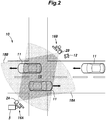
- Figure 2 is an explanatory diagram showing an example of use of the object detection system 1 according to the first embodiment.
- the object detection system 1 can detect moving objects (detection targets) such as vehicles 11 or a pedestrian 12 passing through a road 10 based on measurement records acquired from radars 2A and 2B installed near an intersection along the road 10.
- moving objects detection targets
- radars 2A and 2B installed near an intersection along the road 10.
- the radars 2A and 2B are arranged, for example, at diagonal corners (i.e., opposite corners) of a crossroad 15.
- the radars 2A and 2B are placed in known roadside apparatuses 16A and 16B which can communicate with in-vehicle devices.
- the radars 2A and 2B have substantially fan-shaped measurement areas 18A and 18B, respectively, which are directed toward the center of the crossroad 15.
- the measurement areas 18A and 18B are set such that the measurements areas at least partially overlap each other (a dark shaded area in Figure 2 ), enabling simultaneous detection of moving objects at common locations.
- the object detection device 3 is installed in the roadside apparatus 16A.
- the object detection device 3 detects moving objects based on measurement records acquired from the radars 2A and 2B, and also can detect moving objects based on measurement records acquired from only one of the radars (e.g., the radar 2A).
- the object detection device 3 may be provided integrally with a radar 2.
- the object detection device 3 may be placed in a remote monitoring facility, a traffic control center, or other facilities.
- the object detection system 1 is used for not limited to the detection of moving objects traveling on a road, but also can be used for the detection of moving objects in any facility or transportation.
- Figure 3 is a block diagram showing a schematic configuration of the object detection device 3 according to the first embodiment.
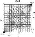
- Figure 4 is an explanatory diagram showing examples of grids (radar grids 41A and 41B for measurement and a processing grid 45 for clustering operations) which are set for measurement areas of the radars 2.
- a communication device 21 is provided with a communication interface for acquiring measurement records from the radars 2.
- An input device 22 includes a known input device such as a keyboard and a mouse, and enables a user (operator) of the object detection device 3 to enter various data or information and perform a setting operation related to an object detection operation.
- a controller 23 includes a processor and performs processing operations such as object detection operations and acquisition of measurement records from the radars 2.
- a grid setter 31 acquires and generates settings data for grids for measurement (hereinafter, referred to as "radar grids") which are set for the measurement areas 18A and 18B for the radars 2A and 2B, respectively.
- the settings data for the radar grids include location data (locations data of measurement points) in the radar grids and other data.
- the grid setter 31 acquires and generates settings data for a grid for clustering operations (hereinafter, referred to as "processing grid”) set for the measurement areas.
- the settings data for the processing grid include location data of measurement points (location data of clustering target points associated with the measurement points) in the processing grid.
- the radar grids 41A and 41B of the radars 2A and 2B are set based on polar coordinates, and have a substantially fan-shaped areas, which correspond to the measurement areas 18A and 18B, respectively.
- Each of the radar grids 41A and 41B is comprised primarily of a plurality of straight lines extending radially outwardly from a corresponding radar 2A or 2B at prescribed angles relative to one another; and a plurality of arcs arranged at different radii from the corresponding radar 2A or 2B, so that each radar grid 41A or 41B includes a plurality of cells Ra or Rb (hereinafter, referred to as "radar cells”) defined by the straight lines and the arcs.
- Ra or Rb hereinafter, referred to as "radar cells
- the processing grid 45 is set based on orthogonal coordinates, and is composed primarily of a plurality of vertical lines extending in the vertical direction at prescribed intervals; and a plurality of horizontal lines extending in the horizontal direction at prescribed intervals, so that the processing grid 4 includes a plurality of cells F (hereinafter, referred to as "processing cells") defined by the vertical lines and the horizontal lines.
- processing cells are a grid determined for processing operations using a DBSCAN algorithm described later.
- each radar cell R (the vertical and horizontal lengths of a substantially rectangular shape) can be set in the range of several cm to 10 cm, for example.
- the size of each processing cell F having a rectangular or square shape can be set in the range of 10 cm to 50 cm, for example.
- the configurations of a radar grid 41 and a processing grid 45 (including the size and shape of each cell) can be changed as appropriate.
- a grid value calculator 32 in the controller 23 calculates a value (hereinafter, referred to as "grid value”) for each processing cell F used in the clustering operations based on measurement records of the radars 2. As will be described later in detail, the grid value calculator 32 calculates such a grid value from the measurement records of the radar 2 (i.e., likelihoods associated with measurements of related radar cells R).
- a cluster generator 33 performs a clustering operation on each processing cell F (clustering target point).
- the cluster generator 33 performs clustering operations according to a well-known DBSCAN (Density-Based Spatial Clustering of Applications with Noise) algorithm.
- a clustering operation of the present disclosure involves neighborhood calculation by using not only distances between a processing cell F and different related processing cells F, but also grid values of the processing cell and the related processing cells F, the grid values being calculated by the grid value calculator 32 described above.
- the neighborhood calculation in a DBSCAN determines (extracts) core points (processing cell F) each having at least minPts neighboring points (minimum number of points) within a radius ⁇ (Eps-neighborhood of that point); and points (processing cell F) having at least one core point within the radius ⁇ .
- the above-described processing operations performed by the grid setter 31, the grid value calculator 32, and the cluster generator 33 can be implemented by the processor executing prescribed programs.
- An information output device 24 includes a known display device such as a liquid crystal display, and displays various information related to object detection operations and operation results thereof.
- a storage 25 includes a known storage device, and can store programs executable by the processor, various types of information related to object detection operations, and operations results thereof.
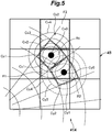
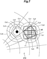
- Figures 5 to 7 are explanatory diagrams showing examples of methods of likelihood calculation performed by the object detection device 3 according to the first embodiment.
- Figure 5 shows an example of an area related to the radar 2A and extending within a relatively short distance from the radar 2A (which means that the size of a processing cell F is relatively larger than the size of a radar cell R).
- Likelihoods associated with the measurement values of the radar cells R1 and R2 are calculated based on the distances from their center points Cx0 and Cy0. In the example of Figure 5 , likelihoods associated with the radar cell R1 are determined between adjoining concentric circles Cx1 to Cx4 around the center point Cx0.
- the likelihood for outside the circle Cx4 may be set to 0.
- the likelihoods associated with the radar cell R2 may be determined between adjoining concentric circles Cy1 to Cy4 around the center point Cy.
- the grid value calculator 32 calculates the maximum value of the likelihoods around the center position Cz1 as a grid value (In this case, the likelihood is set to 0.6 as the likelihood is set to 0.6 in the annular region between Cx1 to Cx2 and the likelihood is set to 0.4 in the annular region between Cy2 to Cy3).
- the grid value calculator 32 can calculate the maximum value of the likelihoods around the center position Cz2 as a grid value (In this case, the likelihood is set to 0.2 in the annular region between Cx3 to Cx4).
- Grid values of processing cells other than the processing cells F 1 and F2 may be set in a similar manner.
- likelihoods associated with measurement values of each radar cell R can be calculated based on distances between each processing cell F and related radar cells R.
- the distance between each processing cell F and a radar cell R can be easily calculated as the distance between the centers of these processing and radar cells.
- the likelihood varies stepwise, with the distance from the center of the radar cell R (the distance between each radar cell R and a processing cell F).
- the variation of likelihood is not limited to this, and the likelihood may linearly vary, with the distance between each radar cell R and a processing cell F.
- the grid value calculator 32 calculates the maximum value of the likelihoods which are set within the processing cell F1, for example, as a grid value of the processing cell F1.
- the grid value calculator 32 calculates a grid value of any other processing cell in the same manner.
- the grid value calculator 32 calculates a sum of the likelihoods associated with the center position Cz1, for example, as a grid value of the processing cell F1.
- the grid value is 1.0 which is a sum of the likelihood of 0.6 in the annular region between Cx1 to Cx2 where the center position Cz1 is present and the likelihood of 0.4 in the annular region between Cy2 to Cy3 where the center position Cz1 is present.
- the grid value calculator 32 calculates a grid value of any other processing cell in the same manner.
- the object detection system 1 calculates a grid value based on the maximum of likelihood values or a sum of likelihood values for each processing cell, thereby ensuring that a clustering operation can be properly performed on measurement records of the radars 2.
- the grid value calculator 32 may use, not only the maximum value or a sum of likelihoods, but also other statistical values (such as an average value and an intermediate value) for a plurality of likelihoods.
- Figure 6 shows an example of areas related to the radars 2A and 2B and extending within a relatively short distance from each of the radar 2A and 2B, in a similar manner to the example of Figure 5 .
- Likelihoods associated with the measurement values of the radar cells R1a and R1b are calculated based on the distances from their center points Cx0 and Cy0 in the same manner as the example in Figure 5 . That is, likelihoods associated with the radar cell R1a are determined between adjoining concentric circles Cx1 to Cx4 around the center point Cx0, while likelihoods associated with the radar cell R1b are determined between adjoining concentric circles Cy1 to Cy4 around the center point Cy0.
- the grid value calculator 32 calculates the maximum value of the likelihoods around the center position Cz1 as a grid value (In this case, the likelihood is set to 0.8 as the likelihood is set to 0.8 in the annular region between Cx0 to Cx1).
- Grid values of processing cells other than the processing cell F1 may be set in a similar manner.
- Figure 7 shows an example of an area located a relatively long distance away from the radar 2A (which means that the size of a processing cell F is relatively smaller than the size of a radar cell R). Likelihoods associated with the measurement value of the radar cell R1 are calculated in the same manner as the example shown in Figure 5 (or Figure 6 ) despite the difference in a relative size of a processing cell F with regard to the radar grid.
- the grid value calculator 32 calculates the maximum value of the likelihoods around the center position Cz1 as a grid value (In this case, the likelihood is set to 1.0 as the likelihood is set to 1.0 at the center point Cy0 where the center position Cz1 is present).
- Grid values of processing cells other than the processing cell F1 may be set in a similar manner.
- Figure 8 is an explanatory diagram showing an outline of neighborhood calculation performed by the object detection device 3 according to the first embodiment.
- the object detection device 3 can perform neighborhood calculation on a processing cell F1at the location a and a processing cell F2 at the location b shown in Figure 8 based on the following equation (1).
- the neighborhood calculation can be performed on processing cells other than the processing cells F1 and F2 in a similar manner.
- a processing cell F to be subjected to the clustering operation is determined as a core point when the processing cell has at least minPts neighboring points (processing cells) which meet the equation (1), and also determined as a point having at least one core point within the radius ⁇ when the processing cell has at least one core point (processing cell) which meets the equation (1).
- the neighborhood calculation forms a cluster comprised of a plurality of processing cells F determined to be core points, and processing cells F determined to have a core point within a radius ⁇ are further assigned to the cluster.
- the object detection system 1 performs a clustering operation on processing cells based on grid values, the grid values being obtained in relation to likelihoods which are calculated based on distances between each processing cell and related radar cells, thereby ensuring that a proper clustering operation can be performed on measurement records of the radars 2.
- Figure 9 is an explanatory diagram showing an output of information (results of clustering operations) provided by the object detection device 3 according to the first embodiment.
- the object detection device 3 can display the results of clustering operations on a display screen 51 of the information output device 24.
- Figure 9 shows an example in which two objects 52 and 53 are detected in the measurement areas 18A and 18B of the radars 2A and 2B.
- Measurement points 55 (indicated by X in Figure 9 ) determined based on the measurement results of the radar 2A are primarily present on the radar 2A side of the objects 52, 53 (the left side in Figure 9 ), and measurement points 56 (indicated by black circles in Figure 9 ) determined based on the measurement results of the radar 2B are primarily present on the radar 2B side of the objects 52 and 53 (the right side in Figure 9 ).
- regions (polygonal regions in the example) formed by clustering a plurality of measurement points 55 and 56 are shown as the detected objects 52 are 53, respectively, in the display screen 51.
- the object detection system 1 can perform accurate clustering operations based on measurement records of the multiple radars 2A, 2B to thereby provide the operation results (the results of object detection operations).
- Figure 10 is a flow chart showing an operation procedure of an object detection operation performed by the object detection device 3 according to the first embodiment.
- the object detection device 3 extracts the coordinates of the center point of each processing cell and the center point of each radar cell, from the settings data of the processing grids 45 and the radar grids 41 preliminarily stored in the storage 25 (ST101, ST102).
- the object detection device 3 determines whether selection of all the radar cells Ri has been completed (ST107). If there is a radar cell Ri of which selection has not been completed (No in ST107), the object detection device 3 selects the next radar cell Ri (ST108) and performs the operation in step ST104 again. The object detection device 3 repeatedly performs the processing steps ST104 to ST106 until the selection of all the radar cells Ri is completed. When the measurement records of the plurality of radars 2 are used for the object detection operation, the object detection device 3 selects the radar cells Ri for all the radars 2.
- the object detection device 3 calculates a grid value of each processing cell Fj to be subjected to the clustering operation (clustering target processing cell) based on the likelihoods calculated in step ST106 (ST109). In this case, the object detection device 3 may set the likelihood calculated in step ST106 as a grid value of the processing cell Fj to be subjected to a clustering operation.
- the object detection device 3 determines whether or not selection of all the processing cells Fj is completed (ST110). If there is a processing cell Fj of which selection is not completed (No in ST110), the object detection device 3 selects the next processing cell Fj (ST111), and performs the operation in step ST103 again. The object detection device 3 repeatedly performs the processing steps ST103 to ST109 until the selection of all radar cells Ri is completed.
- the object detection device 3 performs the clustering operations on the processing cells Fj (ST112).
- the object detection device 3 provides the result of the clustering operations in step ST112 (the results of object detection operations) to the display screen 51 (see Figure 9 ) of the information output device 24 (ST113).
- Figure 11 is a flow chart showing an operation procedure of an object detection operation performed by an object detection device 3 of an object detection system 1 according to a second embodiment of the present invention.
- Figure 12 is an explanatory diagram showing an outline of a selection procedure of methods of likelihood calculation performed in Step ST206 in Figure 11 .
- the object detection device 3 extracts the center point of each processing cell and that of each radar cell (ST201, ST202) in the same manner as steps ST101 and ST102 shown in Figure 10 .
- the object detection device 3 acquires, for each radar cell, an index value used for selecting a likelihood calculation method described later. Examples of such index values include radar reflection intensity measurements and radar Doppler velocities associated with the respective radar cells.
- steps ST203 to ST205 are the same as steps ST103 to ST105 shown in Figure 10 .
- the object detection device 3 selects a method of likelihood calculation based on the index value acquired in step ST202 (ST206).
- the object detection device 3 can select a method of likelihood calculation using a radar reflection intensity measurement as an index value.
- the relationship between the distance (horizontal axis) calculated in step ST205 and the likelihood (vertical axis) calculated in step ST207 described below varies according to radar reflection intensity measurements (preset levels of "strong”, “medium”, and “weak”). That is, when the radar reflection intensity measurement of a radar cell is "strong", the object detection device 3 selects a method of likelihood calculation in which the likelihood, which is calculated in step ST207, decreases from a maximum value of 1, with the distance from the radar cell.
- the object detection device 3 selects a method of likelihood calculation in which the likelihood, which is calculated in step ST207, decreases from a maximum value of 0.8 or 0.6, respectively, with the distance from the radar cell.
- the relationship between the distance and the likelihood according to an index value is not limited to that shown in Figure 12 , and various relationships may be adopted.
- a method of likelihood calculation (the relationship between the distance and the likelihood) may be selected according to radar Doppler velocities.
- step ST207 the object detection device 3 uses the method of likelihood calculation selected in step ST206 (for example, a straight-line equation that corresponds to the radar reflection intensity measurement, "strong" in Figure 12 ) to thereby calculate the likelihood which varies according to the distance from the radar cell.
- the method of likelihood calculation selected in step ST206 for example, a straight-line equation that corresponds to the radar reflection intensity measurement, "strong" in Figure 12
- the object detection system 1 enables proper calculation of likelihoods associated with measurements of radar cells based on a prescribed index (such as radar reflection intensity measurement or radar Doppler velocity).
- steps ST208 to ST214 are the same as steps ST107 to ST113 shown in Figure 10 .
- Figure 13 is a flow chart showing an operation procedure of an object detection operation performed by an object detection device 3 of an object detection system 1 according to a third embodiment of the present invention.
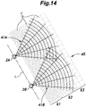
- Figure 14 is an explanatory diagram showing an outline of a method of setting a grid performed in Step ST301 in Figure 13 . Except for what will be discussed here, the object detection system 1 of the third embodiment is the same as the first and second embodiments, of which no further explanation will be made.
- a plurality of radars are arranged side by side so as to have a same reference emission direction, and similarly, radar grids 41A and 41B (measurement areas) are also formed in the same direction.
- the object detection device 3 sets a processing grid 45 such that processing cells F forming the processing grid 45 increase in size with distances from the radars 2A and 2B (ST301).
- the orthogonal coordinates of the processing grid 45 are determined based on a virtual straight line L on which the two radars 2A and 2B are located such that the processing cells F increase in size with distances from the virtual straight line L (ST301).
- the processing cells F have three different sizes in the areas 61 to 63 arranged in order from the virtual straight line L.
- the pattern of variation in the size of the processing cells is not limited to this pattern.
- the processing cells F arranged parallel to the virtual straight line L in a row may have different sizes for each row of the processing cells.
- Steps ST302 to ST314 are the same as steps ST101 to ST113 shown in Figure 10 .
- the object detection system 1 of the third embodiment in which a plurality of radars 2A and 2B are arranged side by side so as to have a same reference emission direction, enables proper setting of radar grids 41A, 41B of the radars 2A, 2B and a processing grid 45 for clustering operation.
- An object detection device, an object detection system, and an object detection method according to the present invention achieve an effect of ensuring that a clustering operation can be properly performed on measurement records of radars, and are useful as an object detection device, an object detection system, and an object detection method for detecting an object based on measurement records of one or more radars.
Landscapes
- Engineering & Computer Science (AREA)
- Radar, Positioning & Navigation (AREA)
- Remote Sensing (AREA)
- Physics & Mathematics (AREA)
- General Physics & Mathematics (AREA)
- Computer Networks & Wireless Communication (AREA)
- Electromagnetism (AREA)
- Chemical & Material Sciences (AREA)
- Analytical Chemistry (AREA)
- Radar Systems Or Details Thereof (AREA)
- Traffic Control Systems (AREA)
Applications Claiming Priority (2)
| Application Number | Priority Date | Filing Date | Title |
|---|---|---|---|
| JP2018076081A JP7015723B2 (ja) | 2018-04-11 | 2018-04-11 | 物体検出装置、物体検出システム、及び物体検出方法 |
| PCT/JP2019/013640 WO2019198532A1 (ja) | 2018-04-11 | 2019-03-28 | 物体検出装置、物体検出システム、及び物体検出方法 |
Publications (2)
| Publication Number | Publication Date |
|---|---|
| EP3779507A1 true EP3779507A1 (de) | 2021-02-17 |
| EP3779507A4 EP3779507A4 (de) | 2021-06-16 |
Family
ID=68163608
Family Applications (1)
| Application Number | Title | Priority Date | Filing Date |
|---|---|---|---|
| EP19784717.1A Pending EP3779507A4 (de) | 2018-04-11 | 2019-03-28 | Objekterkennungsvorrichtung, objekterkennungssystem und objekterkennungsverfahren |
Country Status (4)
| Country | Link |
|---|---|
| US (1) | US11940557B2 (de) |
| EP (1) | EP3779507A4 (de) |
| JP (1) | JP7015723B2 (de) |
| WO (1) | WO2019198532A1 (de) |
Families Citing this family (11)
| Publication number | Priority date | Publication date | Assignee | Title |
|---|---|---|---|---|
| US11580331B2 (en) | 2019-10-25 | 2023-02-14 | Raytheon Company | Classification using cascaded spatial voting grids |
| JP7371907B2 (ja) * | 2019-12-25 | 2023-10-31 | 知洋 下川部 | 船舶の航行支援システムにおける管理サーバ、船舶の航行支援方法、及び船舶の航行支援プログラム |
| WO2021230937A2 (en) * | 2020-02-17 | 2021-11-18 | Raytheon Company | Object tracking using spatial voting |
| WO2021187455A1 (ja) * | 2020-03-18 | 2021-09-23 | 古河電気工業株式会社 | レーダシステム |
| JP2022151979A (ja) * | 2021-03-29 | 2022-10-12 | 古河電気工業株式会社 | レーダ装置、路側位置検出方法及びプログラム |
| CN113325383B (zh) * | 2021-06-17 | 2023-07-04 | 广东工业大学 | 基于网格和dbscan的自适应车载毫米波雷达聚类算法及装置 |
| KR102745644B1 (ko) | 2021-07-14 | 2024-12-23 | (주)스마트레이더시스템 | 레이더를 이용한 타겟 검출 장치 및 방법 |
| KR102722337B1 (ko) * | 2021-12-17 | 2024-10-24 | 국립한국교통대학교산학협력단 | 도로 상황 데이터 처리 장치 및 방법 |
| TWI819613B (zh) * | 2022-05-19 | 2023-10-21 | 緯創資通股份有限公司 | 物件的雙感測方法及用於物件感測的運算裝置 |
| US20240061079A1 (en) * | 2022-08-22 | 2024-02-22 | Nec Laboratories America, Inc. | Scalable biometric sensing using distributed mimo radars |
| DE102023129192A1 (de) * | 2023-10-24 | 2025-04-24 | Valeo Schalter Und Sensoren Gmbh | Erfassung von objekten mit mindestens zwei radarsensoren |
Family Cites Families (16)
| Publication number | Priority date | Publication date | Assignee | Title |
|---|---|---|---|---|
| US5448243A (en) * | 1991-12-30 | 1995-09-05 | Deutsche Forschungsanstalt Fur Luft- Und Raumfahrt E.V. | System for locating a plurality of objects and obstructions and for detecting and determining the rolling status of moving objects, such as aircraft, ground vehicles, and the like |
| FR2709834B1 (fr) * | 1993-09-10 | 1995-11-10 | Framatome Sa | Procédé et dispositif pour la détection et la localisation d'obstacles dans l'environnement d'un véhicule. |
| US7495600B2 (en) * | 2003-12-29 | 2009-02-24 | Itt Manufacturing Enterprise, Inc. | Airfield surface target detection and tracking using distributed multilateration sensors and W-band radar sensors |
| US8665113B2 (en) * | 2005-10-31 | 2014-03-04 | Wavetronix Llc | Detecting roadway targets across beams including filtering computed positions |
| JP2008286582A (ja) | 2007-05-16 | 2008-11-27 | Fujitsu Ten Ltd | レーダ信号処理装置及びレーダ信号処理方法 |
| JP5322789B2 (ja) | 2009-06-15 | 2013-10-23 | 三菱電機株式会社 | モデル生成装置、モデル生成方法、モデル生成プログラム、点群画像生成方法および点群画像生成プログラム |
| US8596587B2 (en) * | 2011-05-09 | 2013-12-03 | Bystep, Llc | Systems and methods for redundant vehicle detection at highway-rail grade crossings |
| US20140152490A1 (en) * | 2012-12-03 | 2014-06-05 | Michael Lehning | Method and Arrangement for the Detection of an Object in a Radar Field |
| JP5892215B2 (ja) | 2014-09-12 | 2016-03-23 | 富士通株式会社 | 目標物管理装置および目標物管理方法 |
| US10018709B2 (en) * | 2014-09-19 | 2018-07-10 | GM Global Technology Operations LLC | Radar target detection via multi-dimensional cluster of reflectors |
| US9759812B2 (en) * | 2014-10-02 | 2017-09-12 | Trimble Inc. | System and methods for intersection positioning |
| JP6770299B2 (ja) | 2015-03-25 | 2020-10-14 | パナソニック株式会社 | 物体検出装置および物体検出方法 |
| EP3358369A4 (de) | 2015-09-30 | 2019-05-08 | Sony Corporation | Informationsverarbeitungsvorrichtung, informationsverarbeitungsverfahren und programm |
| JP6571545B2 (ja) | 2016-01-19 | 2019-09-04 | パナソニック株式会社 | 物体検出装置および物体検出方法 |
| TWI662252B (zh) * | 2016-09-06 | 2019-06-11 | 財團法人工業技術研究院 | 路側偵測系統、路側裝置及其路側通訊方法 |
| LU93431B1 (en) * | 2016-12-27 | 2018-06-28 | Iee Sa | Polarimetric Radar System and Method for Object Classification and Road Condition Estimation in Stationary Applications |
-
2018
- 2018-04-11 JP JP2018076081A patent/JP7015723B2/ja active Active
-
2019
- 2019-03-28 US US17/044,652 patent/US11940557B2/en active Active
- 2019-03-28 WO PCT/JP2019/013640 patent/WO2019198532A1/ja not_active Ceased
- 2019-03-28 EP EP19784717.1A patent/EP3779507A4/de active Pending
Also Published As
| Publication number | Publication date |
|---|---|
| JP2019184438A (ja) | 2019-10-24 |
| WO2019198532A1 (ja) | 2019-10-17 |
| JP7015723B2 (ja) | 2022-02-03 |
| US11940557B2 (en) | 2024-03-26 |
| EP3779507A4 (de) | 2021-06-16 |
| US20210103029A1 (en) | 2021-04-08 |
Similar Documents
| Publication | Publication Date | Title |
|---|---|---|
| EP3779507A1 (de) | Objekterkennungsvorrichtung, objekterkennungssystem und objekterkennungsverfahren | |
| Kim et al. | Placement optimization of multiple lidar sensors for autonomous vehicles | |
| US20210149041A1 (en) | Method and device to improve radar data using reference data | |
| US10101446B2 (en) | Object detection device and object detection method | |
| RU2410849C2 (ru) | Способ и устройство определения географического местонахождения устройства сотовой связи | |
| US20100305858A1 (en) | Non-kinematic behavioral mapping | |
| US20190351896A1 (en) | System and method for vulnerable road user detection using wireless signals | |
| US20150262481A1 (en) | System and method to determine occurrence of platoon | |
| US20110282581A1 (en) | Object and vehicle detection and tracking using 3-d laser rangefinder | |
| JP6659367B2 (ja) | 物体検出装置および物体検出方法 | |
| US11195419B2 (en) | Non-transitory computer-readable storage medium for storing dangerous spot calculation program, dangerous spot calculation method, and dangerous spot calculation apparatus | |
| CN105372506B (zh) | 一种用于区域电磁环境计算的变尺度栅格化方法及系统 | |
| Kim et al. | Signal processing and alert logic evaluation for IoT–based work zone proximity safety system | |
| Moghaddam et al. | Quantifying measurement error in arterial travel times measured by bluetooth detectors | |
| Geissler et al. | Designing a roadside sensor infrastructure to support automated driving | |
| CN111324686B (zh) | 目标测量轨迹的获取方法及装置、存储介质、电子装置 | |
| CN116095826B (zh) | 运动轨迹分析方法、装置、设备及存储介质 | |
| Singh et al. | Power controlled adaptive range radar for self driving vehicles | |
| Minea et al. | Unconventional public transport anonymous data collection employing artificial intelligence | |
| Tabibiazar et al. | Kernel-based optimization for traffic density estimation in ITS | |
| CN112733923A (zh) | 一种确定禁行区域的系统及机器人 | |
| JP2009005250A (ja) | 電波伝搬解析装置 | |
| Tabibiazar et al. | Kernel-based modeling and optimization for density estimation in transportation systems using floating car data | |
| Kopiyawattage et al. | LiDAR aided simulation pipeline for wireless communication in vehicular traffic scenarios | |
| Adu-Gyamfi et al. | A comprehensive data driven evaluation of wide area probe data: opportunities and challenges |
Legal Events
| Date | Code | Title | Description |
|---|---|---|---|
| STAA | Information on the status of an ep patent application or granted ep patent |
Free format text: STATUS: THE INTERNATIONAL PUBLICATION HAS BEEN MADE |
|
| PUAI | Public reference made under article 153(3) epc to a published international application that has entered the european phase |
Free format text: ORIGINAL CODE: 0009012 |
|
| STAA | Information on the status of an ep patent application or granted ep patent |
Free format text: STATUS: REQUEST FOR EXAMINATION WAS MADE |
|
| 17P | Request for examination filed |
Effective date: 20201111 |
|
| AK | Designated contracting states |
Kind code of ref document: A1 Designated state(s): AL AT BE BG CH CY CZ DE DK EE ES FI FR GB GR HR HU IE IS IT LI LT LU LV MC MK MT NL NO PL PT RO RS SE SI SK SM TR |
|
| AX | Request for extension of the european patent |
Extension state: BA ME |
|
| A4 | Supplementary search report drawn up and despatched |
Effective date: 20210518 |
|
| RIC1 | Information provided on ipc code assigned before grant |
Ipc: G01S 13/87 20060101AFI20210511BHEP Ipc: G01S 13/89 20060101ALI20210511BHEP Ipc: G01S 13/91 20060101ALI20210511BHEP Ipc: G08G 1/01 20060101ALI20210511BHEP Ipc: G01S 7/295 20060101ALI20210511BHEP Ipc: G01S 13/72 20060101ALI20210511BHEP Ipc: G01S 13/931 20200101ALI20210511BHEP |
|
| DAV | Request for validation of the european patent (deleted) | ||
| DAX | Request for extension of the european patent (deleted) | ||
| RAP3 | Party data changed (applicant data changed or rights of an application transferred) |
Owner name: PANASONIC HOLDINGS CORPORATION |
|
| STAA | Information on the status of an ep patent application or granted ep patent |
Free format text: STATUS: EXAMINATION IS IN PROGRESS |
|
| 17Q | First examination report despatched |
Effective date: 20240226 |
|
| GRAP | Despatch of communication of intention to grant a patent |
Free format text: ORIGINAL CODE: EPIDOSNIGR1 |
|
| STAA | Information on the status of an ep patent application or granted ep patent |
Free format text: STATUS: GRANT OF PATENT IS INTENDED |
|
| INTG | Intention to grant announced |
Effective date: 20251203 |