EP3779515B1 - Verfahren zur detektion einer falschen synchronisierung eines empfängers mit einem satelliten, entsprechender empfänger und entsprechendes computerprogrammprodukt - Google Patents
Verfahren zur detektion einer falschen synchronisierung eines empfängers mit einem satelliten, entsprechender empfänger und entsprechendes computerprogrammprodukt Download PDFInfo
- Publication number
- EP3779515B1 EP3779515B1 EP20190662.5A EP20190662A EP3779515B1 EP 3779515 B1 EP3779515 B1 EP 3779515B1 EP 20190662 A EP20190662 A EP 20190662A EP 3779515 B1 EP3779515 B1 EP 3779515B1
- Authority
- EP
- European Patent Office
- Prior art keywords
- correlations
- value
- pilot
- periodic
- satellite
- Prior art date
- Legal status (The legal status is an assumption and is not a legal conclusion. Google has not performed a legal analysis and makes no representation as to the accuracy of the status listed.)
- Active
Links
Images


Classifications
-
- G—PHYSICS
- G01—MEASURING; TESTING
- G01S—RADIO DIRECTION-FINDING; RADIO NAVIGATION; DETERMINING DISTANCE OR VELOCITY BY USE OF RADIO WAVES; LOCATING OR PRESENCE-DETECTING BY USE OF THE REFLECTION OR RERADIATION OF RADIO WAVES; ANALOGOUS ARRANGEMENTS USING OTHER WAVES
- G01S19/00—Satellite radio beacon positioning systems; Determining position, velocity or attitude using signals transmitted by such systems
- G01S19/01—Satellite radio beacon positioning systems transmitting time-stamped messages, e.g. GPS [Global Positioning System], GLONASS [Global Orbiting Navigation Satellite System] or GALILEO
- G01S19/13—Receivers
- G01S19/23—Testing, monitoring, correcting or calibrating of receiver elements
-
- G—PHYSICS
- G01—MEASURING; TESTING
- G01S—RADIO DIRECTION-FINDING; RADIO NAVIGATION; DETERMINING DISTANCE OR VELOCITY BY USE OF RADIO WAVES; LOCATING OR PRESENCE-DETECTING BY USE OF THE REFLECTION OR RERADIATION OF RADIO WAVES; ANALOGOUS ARRANGEMENTS USING OTHER WAVES
- G01S19/00—Satellite radio beacon positioning systems; Determining position, velocity or attitude using signals transmitted by such systems
- G01S19/01—Satellite radio beacon positioning systems transmitting time-stamped messages, e.g. GPS [Global Positioning System], GLONASS [Global Orbiting Navigation Satellite System] or GALILEO
- G01S19/13—Receivers
- G01S19/21—Interference related issues ; Issues related to cross-correlation, spoofing or other methods of denial of service
-
- G—PHYSICS
- G01—MEASURING; TESTING
- G01S—RADIO DIRECTION-FINDING; RADIO NAVIGATION; DETERMINING DISTANCE OR VELOCITY BY USE OF RADIO WAVES; LOCATING OR PRESENCE-DETECTING BY USE OF THE REFLECTION OR RERADIATION OF RADIO WAVES; ANALOGOUS ARRANGEMENTS USING OTHER WAVES
- G01S19/00—Satellite radio beacon positioning systems; Determining position, velocity or attitude using signals transmitted by such systems
- G01S19/01—Satellite radio beacon positioning systems transmitting time-stamped messages, e.g. GPS [Global Positioning System], GLONASS [Global Orbiting Navigation Satellite System] or GALILEO
- G01S19/13—Receivers
- G01S19/24—Acquisition or tracking or demodulation of signals transmitted by the system
- G01S19/30—Acquisition or tracking or demodulation of signals transmitted by the system code related
-
- G—PHYSICS
- G01—MEASURING; TESTING
- G01S—RADIO DIRECTION-FINDING; RADIO NAVIGATION; DETERMINING DISTANCE OR VELOCITY BY USE OF RADIO WAVES; LOCATING OR PRESENCE-DETECTING BY USE OF THE REFLECTION OR RERADIATION OF RADIO WAVES; ANALOGOUS ARRANGEMENTS USING OTHER WAVES
- G01S19/00—Satellite radio beacon positioning systems; Determining position, velocity or attitude using signals transmitted by such systems
- G01S19/38—Determining a navigation solution using signals transmitted by a satellite radio beacon positioning system
- G01S19/39—Determining a navigation solution using signals transmitted by a satellite radio beacon positioning system the satellite radio beacon positioning system transmitting time-stamped messages, e.g. GPS [Global Positioning System], GLONASS [Global Orbiting Navigation Satellite System] or GALILEO
-
- H—ELECTRICITY
- H04—ELECTRIC COMMUNICATION TECHNIQUE
- H04B—TRANSMISSION
- H04B1/00—Details of transmission systems, not covered by a single one of groups H04B3/00 - H04B13/00; Details of transmission systems not characterised by the medium used for transmission
- H04B1/69—Spread spectrum techniques
- H04B1/707—Spread spectrum techniques using direct sequence modulation
- H04B1/7073—Synchronisation aspects
- H04B1/7075—Synchronisation aspects with code phase acquisition
- H04B1/70751—Synchronisation aspects with code phase acquisition using partial detection
- H04B1/70752—Partial correlation
Definitions
- the present invention relates to a method for detecting false synchronization of a receiver with a satellite.
- the method according to the invention is implemented after a phase of acquiring a navigation signal from a satellite.
- GNSS Global Navigation Satellite System
- GNSS systems including the GPS system, the GLONASS system and the GALILEO system, which are expected to be put into operational service soon.
- the satellites of such a GNSS system are capable of emitting electromagnetic signals including navigation information.
- Each navigation information generally includes data relating to the time of transmission by the satellite of the corresponding signal and the current position of the satellite.
- the data relating to the current position of the satellite generally contains the almanac giving a rough position of the satellite and the ephemeris giving the exact current position of the satellite.
- Navigation information is carried by a carrier wave and modulated by a spreading code specific to each satellite.
- the signals are emitted by the satellites using a spread spectrum technique.
- the receiver is able to receive the signals emitted by the satellites and to extract the navigation information from them, in particular to determine the distance to the satellite that emitted the corresponding signal. This distance, also called pseudo-distance, is determined by analyzing the propagation time of the corresponding signal.
- the receiver implements digital processing of navigation information from at least three different satellites.
- the receiver needs navigation information from at least four different satellites.
- the receiver implements two phases processing the signals from this satellite.
- the receiver During an initial phase, called in the state of the art, acquisition phase, the receiver generates a local signal containing in particular a local spreading code presenting the image of the satellite spreading code.
- the local signal Since the receiver initially does not know its position, the local signal is not synchronized with the received signal. This means in particular that the local signal is shifted in carrier frequency from the received signal by a value called the Doppler value, and that the spreading code of the received signal is delayed from the local spreading code by a value called the delay value.
- the receiver searches for a peak in the correlations between the local signal and the received signal by trying different Doppler and delay values.
- the receiver determines the Doppler and delay values corresponding to this peak and from these values, launches a next phase, called in the state of the art, the tracking phase.
- the receiver regularly updates the Doppler and delay values, and extracts the navigation information from the signal emitted by the satellite using in particular the local spreading code and the determined Doppler and delay values.
- the receiver At the end of the acquisition phase, the receiver is considered to have synchronized with the satellite or to have "locked" to the satellite.
- the receiver synchronizes its local signal corresponding to the searched satellite with the signal received from another satellite, which leads to an erroneous distance measurement, and therefore potentially to false positioning.
- a conventionally used method is to check the consistency between the satellite position calculated from the ephemeris contained in the navigation information and that calculated from the almanac, which contains the satellite identifiers, unlike the ephemeris. Inconsistency between these values therefore means false synchronization.
- the present invention aims to improve the methods and in particular to detect false synchronization quickly, efficiently and independently of the spreading codes used.
- the invention relates to a method for detecting false synchronization in accordance with claim 1.
- the detection method comprises one or more of the features of claims 2 to 7.
- the invention also relates to a computer program product comprising software instructions which, when implemented by computer equipment, implement a method as defined above.
- the invention also relates to a receiver implementing the procedure as defined above.
- a global satellite positioning system 10 of the GNSS type (from the English “ Global Navigation Satellite System”).
- This global system 10 is for example the GALILEO system.
- the positioning system 10 comprises a plurality of satellites Sat n arranged in different orbits around the Earth for which the positioning system 10 is set up.
- the total number of satellites Sat n is for example equal to 30.
- the index n corresponds to an identifier of each satellite Sat n and varies for example between 1 and 30.
- Each satellite Sat n is capable of emitting electromagnetic signals S towards a part of the Earth's surface 14 that it is currently flying over.
- the satellites Sat n are arranged such that at least four satellites Sat n are capable of transmitting electromagnetic navigation signals S to substantially each point on the Earth's surface 14.
- each satellite Sat n is characterized by the ephemeris relating to this satellite or by its almanac.
- the ephemeris allows the exact position of the satellite Sat n to be determined, while the almanac gives a rough position.
- Each signal S emitted by each of the Sat n satellites includes a data channel containing navigation information.
- such a signal S comprises navigation information modulated by a data spreading code C n d ⁇ c specific to the Sat n satellite that emitted this signal.
- the modulated navigation information is carried by a carrier wave exp ( -j ⁇ p ) using a technique known per se.
- Each signal S emitted by each of the satellites Sat n further comprises a pilot channel comprising a pilot spreading code C n p ⁇ c specific to the Sat n satellite that emitted this signal.
- Each navigation information includes in particular the time of emission of the corresponding signal, the ephemeris and the almanac of the satellite Sat n at the time of emission of the signal S.
- Each data spreading code C n d ⁇ c or pilot C n p ⁇ c presents a pseudo-random type binary code, also known in the state of the art by the English acronym PRN (for “ Pseudo Random Noise” ) .
- Each data spreading code C n d ⁇ c or pilot C n p ⁇ c is a periodic code with a code period denoted L c and expressed in an integer number of reference units.
- the reference unit is, for example, a chip whose duration is denoted T chip and expressed in seconds.
- a "chip” is a reference unit corresponding to a slot of a pseudo-random code.
- the spreading code takes a constant value equal to either +1 or -1.
- the autocorrelation function R n,n takes its maximum value V max .
- the autocorrelation function R n,n takes very small values V compared to V max , that is, V ⁇ V max .
- Each data spreading code C n d ⁇ c allows the navigation information emitted by the Sat n satellite to be modulated.
- Each signal from a Sat n satellite is demodulated using a spreading code which is the local image C n d ⁇ cloc data spreading code C n d ⁇ c or the local image C n p ⁇ cloc of the pilot spreading code C n p ⁇ c corresponding to this satellite.
- each complex signal is transmitted via two carrier waves at the same frequency and synchronously.
- the composite spreading code is the sum of the data spreading codes.
- the positioning system 10 is the GPS system (from the English “ Global Positioning System” ) .
- the signals S emitted by at least some of the satellites Sat n are received by a receiver 20.
- the receiver 20 is for example a portable electronic device.
- the receiver 20 is capable, for example, of moving on the earth's surface 14 or in the vicinity thereof with a variable speed.
- the receiver 20 is capable of receiving signals S from the satellites Sat n , and of extracting from these signals S the navigation information to deduce its current position, its current speed and the time as will be explained later.
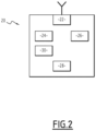
- Receiver 20 is illustrated in more detail in the Figure 2 .
- the receiver 20 comprises an antenna 22, an acquisition module 24, a tracking module 26, a detection module 28, a control module 30 and hardware resources.
- the modules 24, 26, 28 and 30 are presented for example in the form of software which is implemented by the hardware resources provided for this purpose, such as a processor, a RAM, a ROM, etc.
- the hardware resources are for example powered by a battery.
- the read-only memory of the receiver 20 is capable of storing images of the data spreading codes C n d ⁇ c and possibly pilot C n p ⁇ c of each satellite Sat n .
- the antenna 22 is capable of receiving electromagnetic signals S r corresponding to the signals S emitted by the satellites Sat n when these are within an area of its visibility.
- the control module 30 is capable of controlling the operation of the modules 24, 26 and 28.
- the acquisition module 24 is capable of implementing a phase of acquisition of the signals S r according to techniques known per se.
- the tracking module 26 is capable of implementing a tracking phase of the signals S r according to techniques known per se.
- the detection module 28 is capable of implementing a convergence phase, transient between the acquisition phase and the tracking phase.
- the convergence phase notably comprises a method for detecting false synchronization according to the invention. This method will be described in detail later.
- receiver 20 The operation of receiver 20 will now be explained.
- the control module 30 initiates a plurality of acquisition channels for all the satellites Sat n .
- Each of these channels makes it possible to acquire the navigation information from the satellite Sat n with which it is associated, when this satellite Sat n is in the field of visibility of the antenna 22.
- the operation of the receiver 20 on each acquisition channel is substantially similar. Thus, only the operation of the receiver 20 on one channel will be explained below.
- This channel is associated for example with the satellite Sat n , hereinafter called the searched satellite. It is further assumed that the satellite Sat n is located in the visibility range of the antenna 22 and that this satellite is capable of transmitting navigation signals.
- Receiver 20 generates a local data signal S loc d comprising a local carrier wave exp ( -j ⁇ ploc ) and a local data spreading code C n d ⁇ cloc corresponding to a local image of the data spreading code C n d ⁇ c of the satellite sought.
- Receiver 20 further generates a local pilot signal S loc p comprising a local carrier wave exp ( -j ⁇ ploc ) and a pilot local spreading code C n p ⁇ cloc corresponding to a local image of the driver spreading code C n p ⁇ c of the satellite sought.
- control module 30 launches the execution of the acquisition phase which is then implemented by the acquisition module 24.
- the acquisition module 24 determines a Doppler value and a delay value of the received signal S r relative to the local data signal S loc d or pilot S loc p .
- the Doppler value corresponds to the frequency shift of the local carrier wave exp(-j ⁇ ploc ) relative to the carrier wave exp ( -j ⁇ p ) of the received signal S r .
- the delay value corresponds to the delay of the pilot spreading code C n p ⁇ c of this received signal with respect to the pilot local spreading code C n p ⁇ cloc .
- the delay values are determined using known techniques which include the calculation of correlations of three types.
- a first type of correlation consists of calculating correlations between the received signal S r and the local data signal S loc d or pilot S loc p .
- a second type of correlation consists of calculating correlations between the received signal S r and a signal corresponding to the local data signal S loc d or pilot S loc p in which the local spreading code C n d ⁇ cloc + d Or C n p ⁇ cloc + d is shifted in advance by a value d between 0 and T chip .
- a third type of correlation consists of calculating correlations between the received signal S r and a signal corresponding to the local data signal S loc d or pilot S loc p in which the local spreading code C n d ⁇ cloc ⁇ d Or C n p ⁇ cloc ⁇ d is shifted behind by the same value d .
- the receiver 20 synchronizes the local data signal S loc d or pilot S loc p with the signal S emitted by the satellite Sat n searched using the determined Doppler and delay values.
- control module 30 launches the execution of the convergence phase and in particular the method for detecting a false synchronization. This method is notably implemented by the detection module 28.
- the convergence phase performs a control of the delay value of the local spreading code C n d ⁇ cloc Or C n p ⁇ cloc and the Doppler value of the local carrier wave exp ( -j ⁇ ploc) , on the received signal S r , thanks to code and carrier tracking loops, thanks in particular to the three types of correlation mentioned above.
- This transitional phase allows the local spreading code to be precisely matched C n d ⁇ cloc Or C n p ⁇ cloc and the local carrier wave exp ( -j ⁇ ploc ) with the spreading code C n d ⁇ c Or C n p ⁇ c and the carrier wave exp ( -j ⁇ p ) of the received satellite signal S r .
- the detection method implemented during this phase makes it possible to detect a false synchronization of the corresponding acquisition channel with a satellite Sat p other than the desired satellite Sat n .
- the Doppler and delay values determined by the acquisition module 24 correspond to the signal S emitted by a satellite Sat p other than the satellite Sat n sought.
- the control module 30 launches the acquisition phase again.
- control module 30 launches the tracking phase which is then implemented by the tracking module 26.
- the tracking module 26 regularly updates the Doppler and delay values, which allows it to demodulate the received signal S r and extract the corresponding navigation information therefrom. It subsequently transmits this information to the control module 30.
- control module 30 consolidates all of the information acquired by all of the acquisition channels and deduces the position of the receiver 20, its speed and the time.
- this method comprises steps 110, 120 and 130 each corresponding to a criterion of a false synchronization. These criteria are then compared with predetermined thresholds during step 140 which then makes it possible to conclude whether a false synchronization has taken place or not.
- Steps 110 to 130 are independent of one another and can therefore be implemented in parallel or consecutively. In a particular embodiment, at least some of these steps are implemented using results of previous calculations carried out in particular during the acquisition phase.
- the three steps 110 to 130 are implemented and the three criteria are therefore compared with the corresponding thresholds during step 140.
- step 140 only one step among steps 110 to 130 is implemented and the criterion obtained is therefore compared with the corresponding threshold during step 140.
- the detection module 28 determines a plurality of correlation intervals which are for example the same for all of these steps.
- Each correlation interval is thus called a reference interval and will subsequently be identified by the index m varying between 1 and N, N being the total number of reference intervals over the duration of the convergence phase.
- the reference intervals have, for example, approximately the same duration T , which is equal to, for example, 20 ms. This duration T will subsequently be called the reference value.
- the detection module 28 determines a first value v 1 corresponding to the anisotropy of the covariance matrix between the pilot and data channels.
- the detection module 28 first determines a plurality of pilot channel point correlations Z p ( m ) and a plurality of data channel point correlations Z d ( m ).
- the detection module 28 determines a covariance P pp of the pilot channel point correlations Z p ( m ), a covariance P dd of the data channel point correlations, a covariance P pd of the pilot channel point correlations and of the data channel point correlations and a reference power P ref .
- the first value v 1 follows a ⁇ 2 law with two degrees of freedom.
- the detection module 28 determines a second value v 2 using a plurality of partial pilot channel correlations Z pp ( m,p ).
- Each partial pilot channel correlation Z pp ( m,p ) corresponds to a point correlation over an integration interval of length equal to a fraction of the reference value T between the received signal S r and the local pilot signal S loc p .
- the number p determines the type of partial correlation.
- the number p varies between 1 and P , the number P signifying the number of fractions of the reference interval which, in the example described, is equal to 4. Moreover, these fractions all have the same duration which is then equal to T /4.
- the second value v 2 follows a ⁇ 2 law with three degrees of freedom.
- the detection module determines a third value v 3 as a function of a plurality of pilot channel shifted correlations Z pd ( m, ⁇ ) .
- each pilot channel shifted correlation Z pd ( m, ⁇ ) corresponds to a shifted correlation between the received signal S r and a shifted local signal S loc dp corresponding to the local pilot signal S loc p in which the local image of the pilot spreading code C n p ⁇ cloc is shifted by an integer number of chips.
- the third value v 3 follows a ⁇ 2 law with four degrees of freedom.
- the I p+k ( p ) values for the data-path shifted correlations will be determined in a manner analogous to that used to determine these values for the pilot-path shifted correlations.
- step 140 the detection module 28 analyzes the values v 1 , v 2 and v 3 to detect a false synchronization.
- the detection module 28 detects a false synchronization.
- the invention makes it possible to detect a synchronization phase with a satellite independently of the type of spreading codes used.
- This detection is carried out with a high probability, which makes the invention particularly effective.
- the invention has particular advantages when the overall system 10 is the GALILEO system and when, in particular, the receiver according to the invention is used to receive so-called “open” signals from the L1 band.
- step 120 there is no need to recalculate the partial correlations during step 120 when the number P is equal to 4, that is to say when the partial correlations are calculated over a quarter of the reference interval, i.e. 1 millisecond, because these correlations have already been calculated over time intervals of 1 millisecond, corresponding to an integration time commonly used in the satellite channels of the receivers.
Landscapes
- Engineering & Computer Science (AREA)
- Radar, Positioning & Navigation (AREA)
- Remote Sensing (AREA)
- Computer Networks & Wireless Communication (AREA)
- Physics & Mathematics (AREA)
- General Physics & Mathematics (AREA)
- Signal Processing (AREA)
- Position Fixing By Use Of Radio Waves (AREA)
Claims (9)
- Verfahren zur Erkennung einer falschen Synchronisation eines Empfängers (20) mit einem Satelliten während einer Erfassungsphase eines Navigationssignals, das von diesem Satelliten stammt, wobei der Satellit Teil eines globalen Navigationssatellitensystems (10) ist;das Navigationssignal umfassend einen Datenkanal, der Navigationsinformationen umfasst, die durch einen Datenausbreitungscode moduliert werden, der diesem Satelliten eigen ist, und von einer Trägerwelle getragen werden, und einen Steuerkanal, umfassend einen Steuerausbreitungscode, der diesem Satelliten eigen ist und der von einer Trägerwelle getragen wird;wobei der Empfänger (20) während der Erfassungsphase, geeignet ist, um das Navigationssignal, bezeichnet als empfangenes Signal, zu empfangen, das von dem Satelliten emittiert wird, ein lokales Datensignal zu erzeugen, umfassend ein lokales Bild des Datenausbreitungscodes und ein lokales Bild der Trägerwelle, und ein lokales Steuersignal zu erzeugen, umfassend ein lokales Bild des Steuerausbreitungscodes und das lokale Bild der Trägerwelle;wobei das Verfahren nach der Erfassungsphase während einer Konvergenzphase durchgeführt wird und die folgenden Schritte umfasst:- Bestimmen (110) einer Vielzahl von punktuellen Steuerkanalkorrelationen, die jeweils einer punktuellen Korrelation über ein Referenzintervall entsprechen, dessen Dauer gleich wie ein Referenzwert zwischen dem empfangenen Signal und dem lokalen Steuersignal ist, und einer Vielzahl von Datenkanalpunktkorrelationen, die jeweils einer punktuelle Korrelation auf einem der Referenzintervalle zwischen dem empfangenen Signal und dem lokalen Datensignal entsprechen, und Bestimmen eines ersten Werts abhängig von diesen punktuellen Korrelationen;- - Bestimmen (120) einer Vielzahl von partiellen Steuerkanalkorrelationen, die jeweils einer punktuellen Korrelation über ein Referenzintervall entsprechen, dessen Dauer gleich wie eine Fraktion des Referenzwerts zwischen dem empfangenen Signal und dem lokalen Steuersignal ist, und Bestimmen eines zweiten Werts basierend auf diesen partiellen Korrelationen;- Bestimmen (130) einer Vielzahl von versetzten Steuerkanalkorrelationen, die jeweils einer versetzten Korrelation auf einem der Referenzintervalle zwischen dem empfangenen Signal und einem versetzten lokalen Signal entsprechen, das dem lokalen Steuersignal entspricht, in dem das lokale Bild des Steuerausbreitungscodes um eine ganze Zahl von Referenzeinheiten versetzt ist, und Bestimmen eines dritten Werts basierend auf diesen versetzten Steuerkanalkorrelationen;- Bestimmen (140) einer falschen Synchronisation, wenn mindestens einer der Werte von dem ersten Wert, dem zweiten Wert und dem dritten Wert, wenn ein solcher Wert bestimmt wird, einen vorbestimmten Schwellenwert überschreitet; wobei der erste Wert basierend auf Kovarianzen zwischen den punktuellen Steuerkanalkorrelationen und den punktuellen Datenkanalkorrelationen bestimmt wird.
- Verfahren nach Anspruch 1, wobei der erste Wert wie folgt bestimmt wird:
 v 1 der erste Wert ist;N die Anzahl von punktuellen Steuerkanalkorrelationen gleich wie die Anzahl punktuellen Datenkanalkorrelationen ist;Ppp die Kovarianz der punktuellen Steuerkanalkorrelationen ist;Pdd die Kovarianz der punktuellen Datenkanalkorrelationen ist;Ppd die Kovarianz der punktuellen Steuerkanalkorrelationen und der punktuellen Datenkanalkorrelationen ist;Pref eine Referenzleistung ist, die basierend auf den punktuellen Steuerkanalkorrelationen bestimmt wird; undσ2 die Varianz des Rauschens von (Ppp - Pdd ) und von 2Ppd ist.
 - Verfahren nach einem der vorherigen Ansprüche, wobei in dem Schritt des Bestimmungsschritts (120) einer Vielzahl von partiellen Steuerkanalkorrelationen P Typen von partiellen Korrelationen bestimmt werden, wobei eine partielle Korrelation eines gegebenen Typs über einen vorbestimmten Bruchteil eines der Referenzintervalle bestimmt wird.
- Verfahren nach Anspruch 3, wobei der zweite Wert wie folgt bestimmt wird:


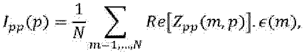 v 2 der zweite Wert ist;N die Anzahl der partiellen Korrelationen ist;ε(m) der sekundäre Code des Steuerkanals ist, der gleich 1 oder -1 ist;Zpp (m,p) eine partielle Korrelation eines Typs p ist, wobei die Zahl p zwischen 1 und P liegt;Pref eine Referenzleistung ist, die basierend auf den punktuellen Steuerkanalkorrelationen bestimmt wird;Re[X] der reale Teil einer komplexen Zahl ist; undσ2 die Rauschvarianz jeder der Funktionen Ipp(p) ist.
 - Verfahren nach einem der Ansprüche 1 bis 3, wobei der zweite Wert ferner abhängig von einer Vielzahl von partiellen Datenkanalkorrelationen bestimmt wird, die jeweils einer punktuellen Korrelation über ein Zeitintervall entsprechen, das gleich wie eine Fraktion des Referenzwerts zwischen dem empfangenen Signal und dem lokalen Datensignal ist.
- Verfahren nach einem der vorherigen Ansprüche, wobei jede versetzte Steuerkanalkorrelation unter Verwendung des lokalen Bilds des vorgezogenen oder verzögerten Steuerausbreitungscodes von einer oder zwei Referenzeinheiten bestimmt wird.
- Verfahren nach einem der vorherigen Ansprüche, wobei der dritte Wert wie folgt bestimmt wird:

 v3 der dritte Wert ist;N die Anzahl versetzter Korrelationen ist;ε(m) der sekundäre Code des Steuerkanals ist, wobei seine Werte gleich 1 oder -1 sind;E eine Teilmenge der Menge {-K,....,-1,1, ...,K} ist, wobei K die maximale Anzahl von Versätzen ist, die in einer Richtung verwendet werden;Zpd (m,kTchip ) eine um k Referenzeinheiten vorgezogene Korrelation ist, wenn k > 0 und eine um k Referenzeinheiten verzögerte Korrelation, wenn k < 0;Pref eine Referenzleistung ist, die basierend auf den punktuellen Steuerkanalkorrelationen bestimmt wird; undσ2 die Rauschvarianz jeder der Funktionen Ip+k (p) ist.
 - Computerprogrammprodukt, umfassend Softwareanweisungen, die, wenn sie von einer Rechenvorrichtung durchgeführt werden, das Verfahren nach einem der vorherigen Ansprüche durchführen.
- Empfänger (20), umfassend ein Erfassungsmodul (28), das konfiguriert ist, um das Verfahren nach einem der Ansprüche 1 bis 7 durchzuführen.
Applications Claiming Priority (1)
| Application Number | Priority Date | Filing Date | Title |
|---|---|---|---|
| FR1909209A FR3099954B1 (fr) | 2019-08-14 | 2019-08-14 | Procede de detection d'une fausse synchronisation d'un recepteur avec un satellite, recepteur et produit programme d'ordinateur associes |
Publications (2)
| Publication Number | Publication Date |
|---|---|
| EP3779515A1 EP3779515A1 (de) | 2021-02-17 |
| EP3779515B1 true EP3779515B1 (de) | 2025-06-18 |
Family
ID=69375414
Family Applications (1)
| Application Number | Title | Priority Date | Filing Date |
|---|---|---|---|
| EP20190662.5A Active EP3779515B1 (de) | 2019-08-14 | 2020-08-12 | Verfahren zur detektion einer falschen synchronisierung eines empfängers mit einem satelliten, entsprechender empfänger und entsprechendes computerprogrammprodukt |
Country Status (4)
| Country | Link |
|---|---|
| US (1) | US11762103B2 (de) |
| EP (1) | EP3779515B1 (de) |
| CA (1) | CA3089548A1 (de) |
| FR (1) | FR3099954B1 (de) |
Family Cites Families (6)
| Publication number | Priority date | Publication date | Assignee | Title |
|---|---|---|---|---|
| US7876738B2 (en) * | 2004-03-02 | 2011-01-25 | Nokia Corporation | Preventing an incorrect synchronization between a received code-modulated signal and a replica code |
| US8149897B2 (en) * | 2006-05-26 | 2012-04-03 | Global Locate, Inc. | Method and apparatus for performing signal correlation for signals received from satellites in multiple satellite systems |
| US9036683B2 (en) * | 2008-10-02 | 2015-05-19 | Texas Instruments Incorporated | Mitigation circuitry generating cross correlation doppler/code LAG variable comparison value |
| FR2974914B1 (fr) * | 2011-05-05 | 2013-05-10 | Thales Sa | Dispositif de reception d'un systeme de positionnement par satellite comprenant une fonction de detection de faux accrochages |
| FR3043790B1 (fr) | 2015-11-13 | 2019-11-01 | Thales | Procede de detection d'une fausse synchronisation d'un recepteur avec un satellite, module et produit programme d'ordinateur associes |
| FR3047567B1 (fr) | 2016-02-09 | 2019-06-21 | Thales | Procede de detection d'une fausse synchronisation d'un recepteur avec un satellite, recepteur et produit programmme d'ordinateur associes |
-
2019
- 2019-08-14 FR FR1909209A patent/FR3099954B1/fr active Active
-
2020
- 2020-08-10 CA CA3089548A patent/CA3089548A1/fr active Pending
- 2020-08-12 EP EP20190662.5A patent/EP3779515B1/de active Active
- 2020-08-13 US US16/993,006 patent/US11762103B2/en active Active
Also Published As
| Publication number | Publication date |
|---|---|
| US20210048536A1 (en) | 2021-02-18 |
| CA3089548A1 (fr) | 2021-02-14 |
| US11762103B2 (en) | 2023-09-19 |
| EP3779515A1 (de) | 2021-02-17 |
| FR3099954A1 (fr) | 2021-02-19 |
| FR3099954B1 (fr) | 2021-07-23 |
Similar Documents
| Publication | Publication Date | Title |
|---|---|---|
| EP3709058B1 (de) | Verfahren zur kontrolliereung der integrität eines funknavigations-satellitensignals und empfänger geeignet zur durchführung des verfahrens | |
| EP4107548B1 (de) | Verfahren zur detektion einer scheinquelle in einem satellitenfunknavigationssignal und zugehörige empfangsvorrichtung | |
| EP2520949B1 (de) | Empfangsvorrichtung eines Satelliten-Positioniersystems, das eine Erkennungsfunktion von Fehlkopplungen umfasst | |
| EP3168648B1 (de) | Verfahren zur detektion einer falschen synchronisierung eines empfängers mit einem satelliten, entsprechendes modul und entsprechendes computerprogrammprodukt | |
| EP1692535B1 (de) | Satellitendaten-erfassungsverfahren | |
| EP2487507B1 (de) | Erfassungsverfahren mit verbesserter frequenzieller Multikorrelation | |
| EP3779515B1 (de) | Verfahren zur detektion einer falschen synchronisierung eines empfängers mit einem satelliten, entsprechender empfänger und entsprechendes computerprogrammprodukt | |
| FR3047567B1 (fr) | Procede de detection d'une fausse synchronisation d'un recepteur avec un satellite, recepteur et produit programmme d'ordinateur associes | |
| CA3260894A1 (fr) | Method for detecting an interfering signal in a gnss receiver and associated detection device | |
| FR3045167A1 (fr) | Procedes et dispositifs de validation de synchronisation entre un recepteur de geolocalisation et un satellite emetteur | |
| EP4165441B1 (de) | Empfänger von funknavigationssignalen mit einem rechner eines korrelationsleistungsindikators | |
| EP2015098A2 (de) | Verfahren zur Bestimmung eines Steuerungsfehlers in einer Abtastschleife mit einem Pseudo-Zufallscode | |
| EP1508816B1 (de) | Verfahren zur Bestätigung der Erfassung einer Korrelationsspitze mittels eines Empfängers für ein satellitengestützes Navigationssystem | |
| EP1962101B1 (de) | Überwachungsverfahren und -system von Schleifen der Code-Verfolgung in einem satellitengesteuerten Positionsempfänger | |
| WO2003054576A1 (fr) | Procede d'amelioration de la determination de l'attitude d'un vehicule a l'aide de signaux de radionavigation par satellite | |
| EP4359825B1 (de) | Verfahren zur detektion einer vielzahl von geolokalisierungssignalen | |
| EP2687869B1 (de) | Erfassungsverfahren von GNSS-Signalen für Satellit, und angepasster Empfänger für die Umsetzung dieses Verfahrens | |
| US20040167713A1 (en) | Using multiple detection algorithms in positioning signal processing | |
| CA2981273A1 (fr) | Module de detection d'un signal perturbateur lors de l'acquisition initiale par un recepteur d'informations de navigation, recepteur comportant un tel module, procede et produit programme d'ordinateur associes | |
| EP2724179B1 (de) | Optimierung eines ortungssystems mit terrestrischen sendebasisstationen | |
| FR2967850A1 (fr) | Methode d'acquisition directe d'un signal de code p(y) par un recepteur gps | |
| FR2968087A1 (fr) | Procede d'acquisition rapide et robuste d'un signal de code p(y) par un recepteur gps | |
| FR2877803A1 (fr) | Procede et dispositif de reception d'un signal de radionavigation degrade |
Legal Events
| Date | Code | Title | Description |
|---|---|---|---|
| PUAI | Public reference made under article 153(3) epc to a published international application that has entered the european phase |
Free format text: ORIGINAL CODE: 0009012 |
|
| STAA | Information on the status of an ep patent application or granted ep patent |
Free format text: STATUS: THE APPLICATION HAS BEEN PUBLISHED |
|
| AK | Designated contracting states |
Kind code of ref document: A1 Designated state(s): AL AT BE BG CH CY CZ DE DK EE ES FI FR GB GR HR HU IE IS IT LI LT LU LV MC MK MT NL NO PL PT RO RS SE SI SK SM TR |
|
| AX | Request for extension of the european patent |
Extension state: BA ME |
|
| STAA | Information on the status of an ep patent application or granted ep patent |
Free format text: STATUS: REQUEST FOR EXAMINATION WAS MADE |
|
| 17P | Request for examination filed |
Effective date: 20210805 |
|
| RBV | Designated contracting states (corrected) |
Designated state(s): AL AT BE BG CH CY CZ DE DK EE ES FI FR GB GR HR HU IE IS IT LI LT LU LV MC MK MT NL NO PL PT RO RS SE SI SK SM TR |
|
| STAA | Information on the status of an ep patent application or granted ep patent |
Free format text: STATUS: EXAMINATION IS IN PROGRESS |
|
| 17Q | First examination report despatched |
Effective date: 20230420 |
|
| P01 | Opt-out of the competence of the unified patent court (upc) registered |
Effective date: 20230425 |
|
| GRAP | Despatch of communication of intention to grant a patent |
Free format text: ORIGINAL CODE: EPIDOSNIGR1 |
|
| STAA | Information on the status of an ep patent application or granted ep patent |
Free format text: STATUS: GRANT OF PATENT IS INTENDED |
|
| INTG | Intention to grant announced |
Effective date: 20250212 |
|
| GRAS | Grant fee paid |
Free format text: ORIGINAL CODE: EPIDOSNIGR3 |
|
| GRAA | (expected) grant |
Free format text: ORIGINAL CODE: 0009210 |
|
| STAA | Information on the status of an ep patent application or granted ep patent |
Free format text: STATUS: THE PATENT HAS BEEN GRANTED |
|
| AK | Designated contracting states |
Kind code of ref document: B1 Designated state(s): AL AT BE BG CH CY CZ DE DK EE ES FI FR GB GR HR HU IE IS IT LI LT LU LV MC MK MT NL NO PL PT RO RS SE SI SK SM TR |
|
| REG | Reference to a national code |
Ref country code: GB Ref legal event code: FG4D Free format text: NOT ENGLISH |
|
| REG | Reference to a national code |
Ref country code: CH Ref legal event code: EP |
|
| REG | Reference to a national code |
Ref country code: DE Ref legal event code: R096 Ref document number: 602020052837 Country of ref document: DE |
|
| REG | Reference to a national code |
Ref country code: CH Ref legal event code: EP |
|
| REG | Reference to a national code |
Ref country code: IE Ref legal event code: FG4D Free format text: LANGUAGE OF EP DOCUMENT: FRENCH |
|
| PG25 | Lapsed in a contracting state [announced via postgrant information from national office to epo] |
Ref country code: FI Free format text: LAPSE BECAUSE OF FAILURE TO SUBMIT A TRANSLATION OF THE DESCRIPTION OR TO PAY THE FEE WITHIN THE PRESCRIBED TIME-LIMIT Effective date: 20250618 |
|
| PGFP | Annual fee paid to national office [announced via postgrant information from national office to epo] |
Ref country code: DE Payment date: 20250812 Year of fee payment: 6 |
|
| REG | Reference to a national code |
Ref country code: LT Ref legal event code: MG9D |
|
| PG25 | Lapsed in a contracting state [announced via postgrant information from national office to epo] |
Ref country code: NO Free format text: LAPSE BECAUSE OF FAILURE TO SUBMIT A TRANSLATION OF THE DESCRIPTION OR TO PAY THE FEE WITHIN THE PRESCRIBED TIME-LIMIT Effective date: 20250918 Ref country code: GR Free format text: LAPSE BECAUSE OF FAILURE TO SUBMIT A TRANSLATION OF THE DESCRIPTION OR TO PAY THE FEE WITHIN THE PRESCRIBED TIME-LIMIT Effective date: 20250919 |
|
| PG25 | Lapsed in a contracting state [announced via postgrant information from national office to epo] |
Ref country code: BG Free format text: LAPSE BECAUSE OF FAILURE TO SUBMIT A TRANSLATION OF THE DESCRIPTION OR TO PAY THE FEE WITHIN THE PRESCRIBED TIME-LIMIT Effective date: 20250618 |
|
| PG25 | Lapsed in a contracting state [announced via postgrant information from national office to epo] |
Ref country code: HR Free format text: LAPSE BECAUSE OF FAILURE TO SUBMIT A TRANSLATION OF THE DESCRIPTION OR TO PAY THE FEE WITHIN THE PRESCRIBED TIME-LIMIT Effective date: 20250618 |
|
| PGFP | Annual fee paid to national office [announced via postgrant information from national office to epo] |
Ref country code: FR Payment date: 20250828 Year of fee payment: 6 |
|
| PG25 | Lapsed in a contracting state [announced via postgrant information from national office to epo] |
Ref country code: RS Free format text: LAPSE BECAUSE OF FAILURE TO SUBMIT A TRANSLATION OF THE DESCRIPTION OR TO PAY THE FEE WITHIN THE PRESCRIBED TIME-LIMIT Effective date: 20250918 |
|
| REG | Reference to a national code |
Ref country code: NL Ref legal event code: MP Effective date: 20250618 |
|
| PG25 | Lapsed in a contracting state [announced via postgrant information from national office to epo] |
Ref country code: LV Free format text: LAPSE BECAUSE OF FAILURE TO SUBMIT A TRANSLATION OF THE DESCRIPTION OR TO PAY THE FEE WITHIN THE PRESCRIBED TIME-LIMIT Effective date: 20250618 |
|
| PG25 | Lapsed in a contracting state [announced via postgrant information from national office to epo] |
Ref country code: NL Free format text: LAPSE BECAUSE OF FAILURE TO SUBMIT A TRANSLATION OF THE DESCRIPTION OR TO PAY THE FEE WITHIN THE PRESCRIBED TIME-LIMIT Effective date: 20250618 |
|
| PG25 | Lapsed in a contracting state [announced via postgrant information from national office to epo] |
Ref country code: PT Free format text: LAPSE BECAUSE OF FAILURE TO SUBMIT A TRANSLATION OF THE DESCRIPTION OR TO PAY THE FEE WITHIN THE PRESCRIBED TIME-LIMIT Effective date: 20251020 |
|
| REG | Reference to a national code |
Ref country code: AT Ref legal event code: MK05 Ref document number: 1804679 Country of ref document: AT Kind code of ref document: T Effective date: 20250618 |
|
| PG25 | Lapsed in a contracting state [announced via postgrant information from national office to epo] |
Ref country code: IS Free format text: LAPSE BECAUSE OF FAILURE TO SUBMIT A TRANSLATION OF THE DESCRIPTION OR TO PAY THE FEE WITHIN THE PRESCRIBED TIME-LIMIT Effective date: 20251018 |
|
| PG25 | Lapsed in a contracting state [announced via postgrant information from national office to epo] |
Ref country code: AT Free format text: LAPSE BECAUSE OF FAILURE TO SUBMIT A TRANSLATION OF THE DESCRIPTION OR TO PAY THE FEE WITHIN THE PRESCRIBED TIME-LIMIT Effective date: 20250618 Ref country code: SM Free format text: LAPSE BECAUSE OF FAILURE TO SUBMIT A TRANSLATION OF THE DESCRIPTION OR TO PAY THE FEE WITHIN THE PRESCRIBED TIME-LIMIT Effective date: 20250618 |
|
| PG25 | Lapsed in a contracting state [announced via postgrant information from national office to epo] |
Ref country code: CZ Free format text: LAPSE BECAUSE OF FAILURE TO SUBMIT A TRANSLATION OF THE DESCRIPTION OR TO PAY THE FEE WITHIN THE PRESCRIBED TIME-LIMIT Effective date: 20250618 |
|
| PG25 | Lapsed in a contracting state [announced via postgrant information from national office to epo] |
Ref country code: PL Free format text: LAPSE BECAUSE OF FAILURE TO SUBMIT A TRANSLATION OF THE DESCRIPTION OR TO PAY THE FEE WITHIN THE PRESCRIBED TIME-LIMIT Effective date: 20250618 |
|
| PG25 | Lapsed in a contracting state [announced via postgrant information from national office to epo] |
Ref country code: EE Free format text: LAPSE BECAUSE OF FAILURE TO SUBMIT A TRANSLATION OF THE DESCRIPTION OR TO PAY THE FEE WITHIN THE PRESCRIBED TIME-LIMIT Effective date: 20250618 |
|
| PG25 | Lapsed in a contracting state [announced via postgrant information from national office to epo] |
Ref country code: SK Free format text: LAPSE BECAUSE OF FAILURE TO SUBMIT A TRANSLATION OF THE DESCRIPTION OR TO PAY THE FEE WITHIN THE PRESCRIBED TIME-LIMIT Effective date: 20250618 Ref country code: RO Free format text: LAPSE BECAUSE OF FAILURE TO SUBMIT A TRANSLATION OF THE DESCRIPTION OR TO PAY THE FEE WITHIN THE PRESCRIBED TIME-LIMIT Effective date: 20250618 |
|
| PG25 | Lapsed in a contracting state [announced via postgrant information from national office to epo] |
Ref country code: ES Free format text: LAPSE BECAUSE OF FAILURE TO SUBMIT A TRANSLATION OF THE DESCRIPTION OR TO PAY THE FEE WITHIN THE PRESCRIBED TIME-LIMIT Effective date: 20250618 |
|
| REG | Reference to a national code |
Ref country code: DE Ref legal event code: R097 Ref document number: 602020052837 Country of ref document: DE |
|
| REG | Reference to a national code |
Ref country code: CH Ref legal event code: H13 Free format text: ST27 STATUS EVENT CODE: U-0-0-H10-H13 (AS PROVIDED BY THE NATIONAL OFFICE) Effective date: 20260324 |
|
| PG25 | Lapsed in a contracting state [announced via postgrant information from national office to epo] |
Ref country code: MC Free format text: LAPSE BECAUSE OF FAILURE TO SUBMIT A TRANSLATION OF THE DESCRIPTION OR TO PAY THE FEE WITHIN THE PRESCRIBED TIME-LIMIT Effective date: 20250618 |
|
| PG25 | Lapsed in a contracting state [announced via postgrant information from national office to epo] |
Ref country code: DK Free format text: LAPSE BECAUSE OF FAILURE TO SUBMIT A TRANSLATION OF THE DESCRIPTION OR TO PAY THE FEE WITHIN THE PRESCRIBED TIME-LIMIT Effective date: 20250618 |
|
| PG25 | Lapsed in a contracting state [announced via postgrant information from national office to epo] |
Ref country code: LU Free format text: LAPSE BECAUSE OF NON-PAYMENT OF DUE FEES Effective date: 20250812 Ref country code: IT Free format text: LAPSE BECAUSE OF FAILURE TO SUBMIT A TRANSLATION OF THE DESCRIPTION OR TO PAY THE FEE WITHIN THE PRESCRIBED TIME-LIMIT Effective date: 20250618 |
|
| PG25 | Lapsed in a contracting state [announced via postgrant information from national office to epo] |
Ref country code: CH Free format text: LAPSE BECAUSE OF NON-PAYMENT OF DUE FEES Effective date: 20250831 |
|
| PLBE | No opposition filed within time limit |
Free format text: ORIGINAL CODE: 0009261 |
|
| STAA | Information on the status of an ep patent application or granted ep patent |
Free format text: STATUS: NO OPPOSITION FILED WITHIN TIME LIMIT |
|
| REG | Reference to a national code |
Ref country code: CH Ref legal event code: L10 Free format text: ST27 STATUS EVENT CODE: U-0-0-L10-L00 (AS PROVIDED BY THE NATIONAL OFFICE) Effective date: 20260430 |