EP3779548A1 - Linsenbewegungsvorrichtung, kameramodul und optische vorrichtung - Google Patents
Linsenbewegungsvorrichtung, kameramodul und optische vorrichtung Download PDFInfo
- Publication number
- EP3779548A1 EP3779548A1 EP20192413.1A EP20192413A EP3779548A1 EP 3779548 A1 EP3779548 A1 EP 3779548A1 EP 20192413 A EP20192413 A EP 20192413A EP 3779548 A1 EP3779548 A1 EP 3779548A1
- Authority
- EP
- European Patent Office
- Prior art keywords
- bobbin
- magnet
- disposed
- coil
- moving device
- Prior art date
- Legal status (The legal status is an assumption and is not a legal conclusion. Google has not performed a legal analysis and makes no representation as to the accuracy of the status listed.)
- Pending
Links
Images


Classifications
-
- G—PHYSICS
- G02—OPTICS
- G02B—OPTICAL ELEMENTS, SYSTEMS OR APPARATUS
- G02B27/00—Optical systems or apparatus not provided for by any of the groups G02B1/00 - G02B26/00, G02B30/00
- G02B27/64—Imaging systems using optical elements for stabilisation of the lateral and angular position of the image
- G02B27/646—Imaging systems using optical elements for stabilisation of the lateral and angular position of the image compensating for small deviations, e.g. due to vibration or shake
-
- G—PHYSICS
- G03—PHOTOGRAPHY; CINEMATOGRAPHY; ANALOGOUS TECHNIQUES USING WAVES OTHER THAN OPTICAL WAVES; ELECTROGRAPHY; HOLOGRAPHY
- G03B—APPARATUS OR ARRANGEMENTS FOR TAKING PHOTOGRAPHS OR FOR PROJECTING OR VIEWING THEM; APPARATUS OR ARRANGEMENTS EMPLOYING ANALOGOUS TECHNIQUES USING WAVES OTHER THAN OPTICAL WAVES; ACCESSORIES THEREFOR
- G03B5/00—Adjustment of optical system relative to image or object surface other than for focusing
- G03B5/04—Vertical adjustment of lens; Rising fronts
-
- G—PHYSICS
- G02—OPTICS
- G02B—OPTICAL ELEMENTS, SYSTEMS OR APPARATUS
- G02B7/00—Mountings, adjusting means, or light-tight connections, for optical elements
- G02B7/02—Mountings, adjusting means, or light-tight connections, for optical elements for lenses
- G02B7/04—Mountings, adjusting means, or light-tight connections, for optical elements for lenses with mechanism for focusing or varying magnification
- G02B7/08—Mountings, adjusting means, or light-tight connections, for optical elements for lenses with mechanism for focusing or varying magnification adapted to co-operate with a remote control mechanism
-
- G—PHYSICS
- G03—PHOTOGRAPHY; CINEMATOGRAPHY; ANALOGOUS TECHNIQUES USING WAVES OTHER THAN OPTICAL WAVES; ELECTROGRAPHY; HOLOGRAPHY
- G03B—APPARATUS OR ARRANGEMENTS FOR TAKING PHOTOGRAPHS OR FOR PROJECTING OR VIEWING THEM; APPARATUS OR ARRANGEMENTS EMPLOYING ANALOGOUS TECHNIQUES USING WAVES OTHER THAN OPTICAL WAVES; ACCESSORIES THEREFOR
- G03B13/00—Viewfinders; Focusing aids for cameras; Means for focusing for cameras; Autofocus systems for cameras
- G03B13/32—Means for focusing
- G03B13/34—Power focusing
- G03B13/36—Autofocus systems
-
- G—PHYSICS
- G03—PHOTOGRAPHY; CINEMATOGRAPHY; ANALOGOUS TECHNIQUES USING WAVES OTHER THAN OPTICAL WAVES; ELECTROGRAPHY; HOLOGRAPHY
- G03B—APPARATUS OR ARRANGEMENTS FOR TAKING PHOTOGRAPHS OR FOR PROJECTING OR VIEWING THEM; APPARATUS OR ARRANGEMENTS EMPLOYING ANALOGOUS TECHNIQUES USING WAVES OTHER THAN OPTICAL WAVES; ACCESSORIES THEREFOR
- G03B17/00—Details of cameras or camera bodies; Accessories therefor
- G03B17/02—Bodies
- G03B17/12—Bodies with means for supporting objectives, supplementary lenses, filters, masks, or turrets
-
- G—PHYSICS
- G03—PHOTOGRAPHY; CINEMATOGRAPHY; ANALOGOUS TECHNIQUES USING WAVES OTHER THAN OPTICAL WAVES; ELECTROGRAPHY; HOLOGRAPHY
- G03B—APPARATUS OR ARRANGEMENTS FOR TAKING PHOTOGRAPHS OR FOR PROJECTING OR VIEWING THEM; APPARATUS OR ARRANGEMENTS EMPLOYING ANALOGOUS TECHNIQUES USING WAVES OTHER THAN OPTICAL WAVES; ACCESSORIES THEREFOR
- G03B3/00—Focusing arrangements of general interest for cameras, projectors or printers
- G03B3/10—Power-operated focusing
-
- H—ELECTRICITY
- H02—GENERATION; CONVERSION OR DISTRIBUTION OF ELECTRIC POWER
- H02K—DYNAMO-ELECTRIC MACHINES
- H02K11/00—Structural association of dynamo-electric machines with electric components or with devices for shielding, monitoring or protection
- H02K11/20—Structural association of dynamo-electric machines with electric components or with devices for shielding, monitoring or protection for measuring, monitoring, testing, protecting or switching
- H02K11/21—Devices for sensing speed or position, or actuated thereby
- H02K11/215—Magnetic effect devices, e.g. Hall-effect or magneto-resistive elements
-
- H—ELECTRICITY
- H02—GENERATION; CONVERSION OR DISTRIBUTION OF ELECTRIC POWER
- H02K—DYNAMO-ELECTRIC MACHINES
- H02K41/00—Propulsion systems in which a rigid body is moved along a path due to dynamo-electric interaction between the body and a magnetic field travelling along the path
- H02K41/02—Linear motors; Sectional motors
- H02K41/035—DC motors; Unipolar motors
- H02K41/0352—Unipolar motors
- H02K41/0354—Lorentz force motors, e.g. voice coil motors
- H02K41/0356—Lorentz force motors, e.g. voice coil motors moving along a straight path
-
- H—ELECTRICITY
- H04—ELECTRIC COMMUNICATION TECHNIQUE
- H04N—PICTORIAL COMMUNICATION, e.g. TELEVISION
- H04N23/00—Cameras or camera modules comprising electronic image sensors; Control thereof
- H04N23/50—Constructional details
- H04N23/54—Mounting of pick-up tubes, electronic image sensors, deviation or focusing coils
-
- H—ELECTRICITY
- H04—ELECTRIC COMMUNICATION TECHNIQUE
- H04N—PICTORIAL COMMUNICATION, e.g. TELEVISION
- H04N23/00—Cameras or camera modules comprising electronic image sensors; Control thereof
- H04N23/50—Constructional details
- H04N23/55—Optical parts specially adapted for electronic image sensors; Mounting thereof
-
- G—PHYSICS
- G03—PHOTOGRAPHY; CINEMATOGRAPHY; ANALOGOUS TECHNIQUES USING WAVES OTHER THAN OPTICAL WAVES; ELECTROGRAPHY; HOLOGRAPHY
- G03B—APPARATUS OR ARRANGEMENTS FOR TAKING PHOTOGRAPHS OR FOR PROJECTING OR VIEWING THEM; APPARATUS OR ARRANGEMENTS EMPLOYING ANALOGOUS TECHNIQUES USING WAVES OTHER THAN OPTICAL WAVES; ACCESSORIES THEREFOR
- G03B2205/00—Adjustment of optical system relative to image or object surface other than for focusing
- G03B2205/0007—Movement of one or more optical elements for control of motion blur
- G03B2205/0023—Movement of one or more optical elements for control of motion blur by tilting or inclining one or more optical elements with respect to the optical axis
-
- G—PHYSICS
- G03—PHOTOGRAPHY; CINEMATOGRAPHY; ANALOGOUS TECHNIQUES USING WAVES OTHER THAN OPTICAL WAVES; ELECTROGRAPHY; HOLOGRAPHY
- G03B—APPARATUS OR ARRANGEMENTS FOR TAKING PHOTOGRAPHS OR FOR PROJECTING OR VIEWING THEM; APPARATUS OR ARRANGEMENTS EMPLOYING ANALOGOUS TECHNIQUES USING WAVES OTHER THAN OPTICAL WAVES; ACCESSORIES THEREFOR
- G03B2205/00—Adjustment of optical system relative to image or object surface other than for focusing
- G03B2205/0053—Driving means for the movement of one or more optical element
- G03B2205/0069—Driving means for the movement of one or more optical element using electromagnetic actuators, e.g. voice coils
Definitions
- the present disclosure relates to a lens moving device, a camera module, and an optical apparatus.
- a camera module may include an image sensor, a printed circuit board configured to deliver electric signals to the image installed on the printed circuit board, an infrared cut-off filter configured to block light in infrared area from incident into the image sensor, and an optical system including at least one lens configured to deliver an image to the image sensor.
- a lens moving device configured to perform auto-focusing function and handshake compensation function may be installed in the optical system.
- the lens moving device may be formed in a variety of ways.
- a voice coil motor is commonly used in the lens moving device.
- the voice coil motor operates by an electromagnetic interaction between a magnet fixed in a housing and a coil unit wound on an outer circumferential surface of a bobbin coupled with a lens barrel.
- the voice coil motor may perform auto-focusing function.
- An actuator module of such voice coil motor may reciprocatively move in a direction parallel to an optical axis whereby a bobbin an up and down motion is elastically supported by an upper and a lower elastic member.
- a lens driving device a camera module and an optical apparatus, which are able to receive location information of a bobbin as a feedback, are provided.
- a lens moving device comprising: a first lens driving unit, including a bobbin having at least one lens installed an inner side of the bobbin and a first coil installed on an outer circumferential surface of the bobbin and a holder member configured to support a magnet arranged at a periphery of the bobbin, and configured to move the bobbin and the first coil in a first direction parallel to an optical axis; a second lens driving unit configured to move the whole first lens driving unit in a second and a third direction different from each other and perpendicular to an optical axis, by an interaction between the magnet and a second coil; a circuit board including a base arranged by being spaced from the bobbin and the first lens driving unit at a predetermined interval, a support member configured to movably support the first lens driving unit so that the first lens driving unit can move in a second and a third direction with respect to the base and to supply electric power to the first coil, and a detection sensor
- the cover member may be formed of a ferromagnetic substance.
- the bobbin may be arranged at a position where the sensing magnet does not interfere with the coil unit.
- the sensing magnet may be arranged at a position upper than the coil unit.
- a virtual line connecting a center of the sensing magnet to a center of the correction magnet may pass through a center of the bobbin.
- the sending magnet and the correction magnet may be arranged as not to face contact with the magnet.
- the location detection sensor may be a Hall sensor.
- a camera module comprising: an image sensor; a printed circuit board installed with the image sensor; and a first lens moving device formed as described in the above.
- a lens moving device comprising: a bobbin; a first driving unit coupled to the bobbin; a second driving unit configured to move the first driving unit through an electromagnetic interaction with the first driving unit; a sensing magnet disposed on one side of the bobbin; a location detection sensor configured to sense a location of the sensing magnet; and a correction magnet disposed on an opposite side of the bobbin.
- the sensing magnet and the correction magnet may be spaced at a distance symmetrical to a center of the bobbin.
- a center of the bobbin may be located on a virtual line connecting the sensing magnet and the correction magnet.
- the sensing magnet and the correction magnet may have a shape and size symmetrical to each other.
- the sensing magnet and the correction magnet may be disposed as to maintain a magnetic force equilibrium between each other.
- the first driving unit and the sensing magnet may be disposed as being spaced in a direction corresponding to a direction of an optical axis of a lens module coupled to an inner side of the bobbin.
- the lens moving device may further include: a holder member disposed at an outer side of the bobbin, the second driving unit coupled to the holder member; and an elastic member configured to elastically connect the bobbin and the holder member.
- the elastic member may include: an upper elastic member configured to elastically connect an upper portion of the bobbin and an upper portion of the holder member; and a lower elastic member configured to elastically connect a lower portion of the bobbin and a lower portion of the holder member.
- the second driving unit may be arranged at a corner portion formed whereby a first side surface and a second side surface of the holder member encounter with each other, and the sensing magnet may be disposed as being facing to the first side surface.
- the bobbin may include: a first outer circumferential surface being facing to the first side surface; a second outer circumferential surface being facing to the second side surface; and a third outer circumferential surface being facing to the corner portion, wherein the sensing magnet is disposed on the first outer circumferential surface.
- the location detection sensor may be inserted in a accommodation portion formed whereby a portion of an outer circumferential surface of the holder member is internally recessed.
- the lens moving device may further include: a third driving unit configured to move the second driving unit through an electromagnetic interaction with the second driving unit; a base, the third driving unit coupled to the base; and a support member configured to elastically connect the holder member and the base.
- the first driving unit may include a first coil
- the second driving unit may include a magnet
- the third driving unit may include a second coil
- the bobbin may be movably supported, by the elastic member, in a direction corresponding to a direction of an optical axis of a lens module coupled to an inner side of the bobbin with respect to the holder member, and the holder member may be movably supported, by the support member, in a direction different from a direction of an optical axis of the lens module with respect to the base.
- the support member may include four leaf springs.
- the sensing magnet may include a pair of polarities (N, S) disposed on a surface opposite to the location detection sensor.
- a camera module comprising: a lens module; a bobbin, the lens module disposed on an inner side of the bobbin; a first driving unit coupled to the bobbin; a second driving unit configured to move the first driving unit through an electromagnetic interaction with the first driving unit; a sensing magnet disposed on a side of the bobbin; a location detection sensor configured to sense a location of the sensing magnet; and a correction magnet disposed on another side of the bobbin.
- the camera module may further include: a controller configured to move the bobbin by applying electric power to the first driving unit, wherein the controller may control the electric power applied to the first driving unit by receiving a location of the sensing magnet sensed by the location detection sensor.
- an optical apparatus comprising: a main body; a display unit configured to display information, by being disposed on the main body; and a camera module configured to photograph a picture or motion picture, by being installed in the main body, wherein the camera module may include: a lens module; a bobbin, the lens module disposed on an inner side of the bobbin; a first driving unit coupled to the bobbin; a second driving unit configured to move the first driving unit through an electromagnetic interaction with the first driving unit; a sensing magnet disposed on a side of the bobbin; a location detection sensor configured to sense a location of the sensing magnet; and a correction magnet disposed on another side of the bobbin.
- a location of the bobbin during auto-focusing and handshake compensation operations may be accurately detected, because the location of the sensing magnet may be detected by the location detection sensor such as Hall sensor, by installing the sensing magnet on an outer side surface of the bobbin.
- the location detection sensor such as Hall sensor
- a tiling of the bobbin to a side of the cover member may be prevented, because an attractive force formed between the sensing magnet attached on the bobbin and the cover member made of a metallic material may be offset by an attractive force formed between the correction magnet installed on a side opposite to the sensing magnet and the cover member.
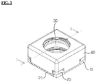
- FIG. 1 is a schematic perspective view illustrating a camera module according to an exemplary embodiment of the present disclosure
- FIG. 2 is an exploded perspective view of FIG. 1
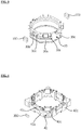
- FIG. 3 is an enlarged perspective view illustrating a bobbin of FIG. 2
- FIG. 4 is an enlarged perspective view illustrating a holder member of FIG. 2
- FIG. 5 is an I-I sectional view of FIG. 1 .
- a lens moving device may include a first lens driving unit (1) and a second lens driving unit (2).
- the first lens driving unit (1) is a lens driving unit for auto-focusing function
- the second lens driving unit (2) is a lens driving unit for handshake compensation function.
- a first driving unit (31) may also refer to as a first coil (31), which is an example of the first driving unit (31), and vice versa.
- a second driving unit (41) may also refer to as a magnet (41), which is an example of the second driving unit (41), and vice versa.
- a third driving unit (23) may also refer to as a second coil (23), which is an example of the third driving unit (23), and vice versa.
- the first lens driving unit (1) may include a base (20), a bobbin (30), a holder member (40) and a cover member (60).
- the cover member (60) may form an outer contour of the camera module. Otherwise, as illustrated in the drawings, a holder member (40) supporting the magnet (41) (to be described hereinafter) may be further arranged an inner side of the cover member (60).
- the base (20) may be coupled to the cover member (60).
- the bobbin (30) may be installed in an internal space of the cover member (60), as being reciprocatively movable in a direction of optical axis.
- a first coil (31) may be installed in a coil accommodation portion (30a) formed on an outer circumferential surface of the bobbin (30).
- An upper (51) and a lower elastic member (52) may be installed on an upper portion and a lower portion of the bobbin (30), respectively.
- An end of the upper elastic member (51) may be connected to the bobbin (30), and another end of the upper elastic member (51) may be coupled to the holder member (40), but not limited hereto.
- the other end of the upper elastic member (51) may be coupled to the cover member (60), as circumstances requires.
- the other end of the upper elastic member (51) may be coupled to an upper surface or a lower surface of the holder member (40), when coupled to the holder member (40).
- An end of the lower elastic member (52) may be connected to the bobbin (30), and another end of the lower elastic member (51) may be coupled to an upper surface of the base, or may be coupled to a lower surface of the holder member (40).
- a protrusion may be formed on a lower side of the base (20) so as to couple the lower elastic member (52).
- a hole or recess may be formed on the lower elastic member (52), on a position corresponding to the position of the protrusion, so as to fix the lower elastic member by the coupling between the protrusion and the hole or recess.
- an adhesive may be additionally used for stronger coupling.
- the upper elastic member (51) may be provided as two springs in a bi-divisional structure.
- the lower elastic member (52) may be formed a single body, so as to function as a socket for being applied with current. That is, the current applied through a terminal (not illustrated in the drawings) may be delivered through two springs of the upper elastic member (52), and the delivered current may be applied to the first coil (31) wound on the bobbin (30).
- the upper elastic member (51) and the first coil (31) may be conductively connected using a method such as soldering, respectively.
- both distal ends of the two springs and the firt coil (31) may be electrically connected using means such as soldering, Ag epoxy, welding, conductive epoxy, etc.
- the present disclosure is not limited hereto.
- the lower elastic member (53) may be formed in a bi-divisional structure, and the upper elastic member (51) may be formed in a single body.
- a bidirectional movement in a direction of an optical axis by the bobbin (30) may be supported by the upper and the lower elastic member (51, 52). That is, the bobbin (30) may be spaced from the base (20) at a predetermined distance so that the bobbin (30) can be controlled to move upward and downward with an initial position of the bobbin (30) as a center.
- the initial position of the bobbin (30) may be an upper surface of the base (20), so that bobbin (30) can be controlled to move only upward with an initial position of the bobbin (30) as a center.
- the first coil (31) may be provided as a coil block in a shape of ring, but not limited hereto. That is, the first coil (31) may be directly wound on an outer circumferential surface of the bobbin (30). As illustrated in FIG. 2 , the first coil (31) may be installed at a position near to a lower surface of the bobbin (30), and may include a straight surface and a curved surface according to a shape of the bobbin (30).
- the first coil (31) formed as a coil block may be in an angular shape, and may be in an octagonal shape. That is, the first coil (31) may be all formed of straight surfaces with no curved surface. This is by consideration of electromagnetic interaction with the magnet (41) disposed oppositely. That is, the electromagnetic force may be maximized when both surfaces of the magnet (41) and the first coil (31) opposing to each other are flat surfaces.
- the surfaces of the magnet (41) and the first coil (31) may be formed as all curved surfaces, all flat surfaces, or one as curved surfaces and the other as flat surfaces, according to its design specification.
- the bobbin (30) may include a fist surface flatly formed on a surface responding to the straight surface of the first coil (31) and a second surface roundly formed on a surface responding to the curved surface of the first coil (31), so that the fist coil (31) can be coupled to an outer circumferential surface of the bobbin (30), but not limited. That is, the second surface may be also formed as a flat surface.
- the holder member (40) may be formed as a frame roughly in a shape of hexahedron. Coupling structures for the upper and the lower elastic member (51, 52) to be coupled may be provide on an upper and a lower surface of the holder member (40), respectively.
- a magnet (41) may be installed at four edge portions of the holder member (40). Here, a accommodation portion (not illustrated in the drawings) may be formed at a position in which the magnet (41) is to be installed as illustrated in FIG. 2 .
- the present disclosure is not limited hereto. That is, the magnet (41) may be adhesively fixed directly to an inner circumferential surface of the holder member (40). The magnet (41) may be fixed by bonding on a side surface or on an edge of the holder member (40), when the magnet (41) is directly fixed to the holder member (40) in such way as described in the above.
- the lens moving device may include only a cover member (60), without including a separate holder member (40).
- the cover member (60) may be formed of a metallic material which is a ferromagnetic substance such as iron.
- the cover member (60) may be provided in an angular shape when viewed from the above, so as to cover a whole of the bobbin (30).
- the cover member (60) may be in a quadrilateral shape as illustrated in FIGS 1 and 2 . Otherwise, although it is not illustrated in the drawings, the cover member (60) may be provided in an octagonal shape.
- the magnetic field emitted from edges of the holder member (40) may be minimized, in case that the cover member is in an octagonal shape when viewed from the above and the magnet arranged at an edge of the holder member (40) is in a trapezoid shape when viewed from the above.
- the lens moving device may include a sensing unit for sensing motion of the bobbin (30).
- the sensing unit may include a sensing magnet (100) and a first location detection sensor (300).
- the first location detection sensor (300) may be installed on the holder member (40).
- the sensing magnet (100) may be formed smaller and thinner than the magnet (41). As illustrated in the drawings, the sensing magnet (100) may be polarized into an upper and a lower portion, but not limited hereto.
- the sensing magnet (100) may be formed in a variety of shapes such as square, triangle, polygon, circle, etc.
- the second driving unit (41) may be arranged at a corner portion (40c) formed whereby a first side surface (40a) and a second side surface (40b) of the holder member (40) encounter with each other, and the sensing magnet (100) may be disposed as being opposite to the first side surface (40a).
- the bobbin (30) may include a first outer circumferential surface (30c) being opposite to the first side surface (40a), a second outer circumferential surface (30d) being opposite to the second side surface (40b), and a third outer circumferential surface (30e) being opposite to the corner portion (40c).
- the sensing magnet (100) may be disposed on the first outer circumferential surface (30c). That is, the sensing magnet (100) may be disposed not opposite to the second driving unit (41). In other words, the sensing magnet (100) may be so arranged as to minimize magnetic force effect with respect to the second driving unit (41).
- the sensing magnet (100) may be installed on an outer circumferential surface of the bobbin (30).
- the sensing magnet (100) may be fixed in a sensing magnet reception area (30b) formed on the bobbin (30) using such as adhesive, glue, etc.
- the sensing magnet reception area (30b) may be provided as a concave groove concavely formed on an outer circumferential surface of the bobbin (30), but not limited hereto.
- the sensing magnet reception area (30b) may be formed as a rib on a position where the sensing magnet (100) can be arranged.
- a concave depth of the sensing magnet reception area (30b) may be formed responding to a thickness of the sensing magnet (100), or otherwise, may be formed lower of higher than the thickness of the sensing magnet (100). Therefore, the sensing magnet (100) may not be protruded out of the guide, when the sensing magnet (100) is fixed in the sensing magnet reception area (30b) using such as adhesive, glue, etc.
- the sensing magnet (100) may be arranged at a position not interfering with the fist coil (31). That is, when the first coil (31) is installed on a lower portion of the bobbin (30) as illustrated in FIG. 3 , the sensing magnet (100) may be arranged on an upper portion of the bobbin (30), or vice versa. This is in order to so locate the first coil (31) as not to affect upward/downward movement of the bobbin (30) in a direction of optical axis.
- the sensing magnet (100) may also be arranged between the first coil (31) and the bobbin (30), or otherwise, may be arranged on an upper surface of the first coil (31) being opposite to the cover member (60) or the holder member (40).
- the sensing magnet (100) may be so arranged as not to be opposite to the magnet (41), as illustrated in FIGS. 2 and 3 . That is, the sensing magnet (100) may be so arranged as to face a side wall of the holder member (40), as not to be opposite to the magnet (41), because four of the magnets (41) may be respectively installed at internal edge portions of the holder member (40).
- the reason of such arrangement of the sensing magnet (100) as not to be opposite to the magnet (41) is, in order to prevent interference between magnetic force change of the sensing magnet (100) and magnetic force of the magnet (41) and to enable the first location detection sensor to accurately feedback a motion of the bobbin (30).
- the sensing magnet (100) may be arranged on an upper portion or a lower portion of the magnet (41), as well as not being opposite to the magnet (41).
- the sensing magnet (100) may be polarized into an upper and a lower portion. Therefore, the first location detection sensor (300) may detect upward/downward movement of the sensing magnet (100), so as to accurately detect upward/downward movement of the bobbin (30).
- the first location detection sensor (300) may be conductively connected to the circuit board (21), and may output a location detection signal of the bobbin (30).
- a separate board may be arranged on a side wall of the holder member (40), and may be conductively connected with the first location detection sensor (300).
- the first location detection sensor (300) may be inserted in a location detection sensor accommodation portion (45) formed on an outer circumferential surface of the holder member (40).
- a location detection sensor accommodation portion (45) formed on an outer circumferential surface of the holder member (40).
- an internal side of the side wall where the accommodation portion (45) is formed may form a concave area, so that a thickness of the holder member (40) can become the thinnest part at the accommodation portion (45).
- the distance between the first location detection sensor (300) and the sensing magnet (100) may be minimized, so that movement of the bobbin (30) can be detected more accurately.
- a correction magnet (200) may be installed on a surface opposite to the surface on which the sensing magnet (100) is installed.
- the correction magnet (200) may be installed on an outer circumferential surface of the bobbin (30).
- the correction magnet (200) may be fixed in a correction magnet reception area (not illustrated in the drawings) provided on the bobbin (30) using such as adhesive.
- the correction magnet reception area may be provided as a concave groove concavely formed on an outer circumferential surface of the bobbin (30), but not limited hereto.
- the correction magnet reception area may be formed as a rib on a position where the correction magnet (200) can be arranged.
- the correction magnet reception area may be provided in a same shape as that of the sensing magnet reception area described in the above.
- a concave depth of the correction magnet reception area may be formed responding to a thickness of the correction magnet (200), or otherwise, may be formed lower of higher than the thickness of the correction magnet (200). Therefore, the sensing magnet (100) may not be protruded out of the guide, when the correction magnet (200) is fixed in the correction magnet reception area using such as adhesive, glue, etc.
- the sensing magnet (100) and the correction magnet (200) may be provided in the same size.
- a center of the sensing magnet (100) may be aligned with a center of the correction magnet (200).
- the attractive force generated among the sensing magnet (100), the correction magnet (200) and the cover member (60) may be offset with one another, so that the center of the bobbin (30) is not tilting by being attracted to the cover member (60) side. Therefore, the bobbin (30) may not tilt to the cover member (60) side and may be arranged near the center where the attractive force among the sensing magnet (100), the correction magnet (200) and the cover member (60) establish equilibrium. Thereby, the bobbin (30) may move in a direction of optical axis, with the center of the bobbin (30) aligned with the optical axis.
- the sensing magnet (100) and the correction magnet (200) are disposed as to be opposite to a flat straight surface of the cover member (60) is described in the above.
- the present disclosure is not limited hereto.
- the sensing magnet (100) and the correction magnet (200) may be disposed as to be opposite to an edge of the cover member (60).
- the first lens driving unit (1) may be formed as described in the above. Otherwise, the first lens driving unit (1) may be replaced with an optical system implementing another auto-focusing function than the structure described in the above. That is, the first lens driving unit (1) may be formed of an optical module using a single-lens moving actuator or an actuator of variable reactive index type, instead of using an auto-focusing actuator of voice coil motor type. That is, any kind of optical actuator which is able to perform auto-focusing function may be used in the first lens driving unit (1).
- the second lens driving unit (2) is a lens driving unit for handshake compensation function.
- the second lens driving unit (2) may include a first lens driving unit (1), a base (20), a support member (42), a first and a second circuit board (21, 22), a second coil (23) and a second location detection sensor (21a).
- a control element to drive the lens moving device may be installed on the first circuit board (21).
- a second coil (23) in a pattern shape may be formed on the second circuit board (22).
- the first and the second circuit board (21, 22) may be conductively connected to each other.
- the second circuit board (22) may be arranged by being laminated on an upper side of the first circuit board (21).
- the second lens driving unit (2) may include only the first circuit board (21), omitting the second circuit board (22). In such case, the second coil (23) may be assembled on the first circuit board (21) as a separate component.
- the second coil (23) may move by shifting the whole of the first lens driving unit (1) in a direction of a flat surface perpendicular to the optical axis, through an interaction with the magnet (41). As illustrated in FIG. 2 , the second coil (23) may be formed on the second circuit board (22) by a pattern coil method. The second coil (23) may be arranged at each of edge portions of the second circuit board (22), as a position responding to a bottom surface of the magnet (41).
- the second location detection sensor (21a) may be installed on the first circuit board (21), but not limited hereto.
- the second location sensor (21a) may be arranged separately as an independent component, or otherwise, may be arranged on the second circuit board (22).
- the second location detection sensor (21a) may detect movement of the holder member (40) in which the magnet (41) is installed, in a direction perpendicular to the optical axis.
- the time required for auto-focusing operation and handshake compensation may be reduced, because movement of the bobbin (30) in a direction of optical axis may be received as a feedback using the sensing magnet (100).
- the auto-focusing function may be performed more accurately and rapidly without risk of degradation of response characteristic, because the first coil (31) may operate while being wound on the bobbin (30), the sensing magnet (100) smaller than the magnet for auto-focusing function may be installed on the bobbin (30), and the first location detection sensor (300) may be arranged by adhering to a side wall of the lens moving device.
- the bobbin (30) may maintain a constant position with respect to the center of the cover member (60), because the correction magnet (200) having the same size and magnetic force as those of the sensing magnet (100) may be installed with their centers aligned on an opposite side of the bobbin (30), so that the bobbin (30) is not eccentric to the cover member (60) side.
- the lens driving device having the sensing magnet (100) and the correction magnet (200) formed as illustrated in FIGS. 1 to 5 may be controlled in a single direction, and may also controlled bi-directionally. That is, the base (20) and the bobbin (30) may be arranged by adhering onto their initial position. For example, a stopper (25) may be form the initial position by being protruded on the base (20) side and contacting with a bottom surface of the bobbin (30). Otherwise, although it is not illustrated in the drawings, the stopper may be protruded on the bottom surface of the bobbin (30) and may be arranged by contacting with an upper surface of the base (20).
- a predetermined prepress may be applied to the upper and the lower elastic member (51, 52), so that the initial position of the bobbin (30) can adhere to the base (20).
- the bobbin (30) may move upward by the electromagnetic interaction, when electric power is applied.
- the bobbin (30) may return to the initial position by the restoring force of the upper and the lower elastic member (51, 52), when the electric power is shut off.
- the base (20) and the bobbin (30) may be arranged by being spaced from the initial position at a predetermined distance.
- the upper and lower elastic member (51, 52) may be formed in a flat shape with no prepress applied. Otherwise, the upper and lower elastic member (51, 52) may be formed with a predetermined prepress applied.
- the bobbin (30) may move upward or downward according to the polarity of current, when the electric power is applied in the initial state where the bobbin (30) is spaced from the base (20) at a predetermined distance. That is, the bobbin (30) may move upward with the initial position as a standard, when constant current is applied. In addition, the bobbin (30) may move downward with the initial position as a standard, when reverse current is applied.
- time required for auto-focusing operation may be minimized, because more accurate position of the bobbin (30) can be detected using the sensing magnet (100), when performing auto-focusing function by controlling the bobbin (30) to move upward or downward.
- the correction magnet (200) installed at a side opposite to the sensing magnet (100) may offset the attractive force between the sensing magnet (100) and the cover member (60), so that the bobbin (30) can move while keeping coaxial with the cover member (60) as far as possible.
- the camera module may include a lens moving device formed as described in the above, a lens barrel (32) coupled to the bobbin (30), an image sensor (11) and a printed circuit board (10).
- the image sensor (11) may be mounted on the printed circuit board (10).
- the printed circuit board (10) may be form a bottom surface of the camera module.
- the bobbin (30) may include a lens barrel. At least one lens may be installed in the lens barrel.
- the lens barrel may be screw-coupled to an inside of the bobbin (30), but not limited hereto.
- the lens barrel may be fixed to an inside of the bobbin (30) by other means than the screw-coupling, or otherwise, one or more lenses may be integrally formed with the bobbin (30) as a single body.
- the lens may be formed of a single piece, or otherwise, may be formed of two or more lenses composing an optical system.
- An infrared cut-off filter may be additionally installed at a positon responding to the image sensor (11) on the base (20).
- the base (20) may be coupled to the holder member (40).
- the base (20) may support a lower side of the holder member (40).
- a separate terminal member may be installed on the base (20), in order for conductivity with the printed circuit board (10).
- the terminal may be integrally formed with the base (20) using such as surface electrodes.
- the base (20) may function as a sensor holder to protect the image sensor (11).
- a protrusion may be formed in a downward direction along a side surface of the base (20).
- this is not an essential structure. Therefore, although it is not illustrated in the drawings, a separate sensor holder may be arranged at a lower portion of the base (20) and function as the sensor holder.
Landscapes
- Physics & Mathematics (AREA)
- General Physics & Mathematics (AREA)
- Engineering & Computer Science (AREA)
- Optics & Photonics (AREA)
- Power Engineering (AREA)
- Signal Processing (AREA)
- Multimedia (AREA)
- Chemical & Material Sciences (AREA)
- Microelectronics & Electronic Packaging (AREA)
- Electromagnetism (AREA)
- Combustion & Propulsion (AREA)
- Lens Barrels (AREA)
- Adjustment Of Camera Lenses (AREA)
Applications Claiming Priority (3)
| Application Number | Priority Date | Filing Date | Title |
|---|---|---|---|
| KR1020140070525A KR102296305B1 (ko) | 2014-06-11 | 2014-06-11 | 렌즈 구동장치 및 이를 구비한 카메라 모듈 |
| EP17184943.3A EP3264150B1 (de) | 2014-06-11 | 2015-06-11 | Linsenbewegungsvorrichtung, kameramodul und optische vorrichtung |
| EP15171596.8A EP2955557B1 (de) | 2014-06-11 | 2015-06-11 | Kameramodul und optische vorrichtung |
Related Parent Applications (3)
| Application Number | Title | Priority Date | Filing Date |
|---|---|---|---|
| EP15171596.8A Division EP2955557B1 (de) | 2014-06-11 | 2015-06-11 | Kameramodul und optische vorrichtung |
| EP17184943.3A Division-Into EP3264150B1 (de) | 2014-06-11 | 2015-06-11 | Linsenbewegungsvorrichtung, kameramodul und optische vorrichtung |
| EP17184943.3A Division EP3264150B1 (de) | 2014-06-11 | 2015-06-11 | Linsenbewegungsvorrichtung, kameramodul und optische vorrichtung |
Publications (1)
| Publication Number | Publication Date |
|---|---|
| EP3779548A1 true EP3779548A1 (de) | 2021-02-17 |
Family
ID=53397883
Family Applications (3)
| Application Number | Title | Priority Date | Filing Date |
|---|---|---|---|
| EP15171596.8A Active EP2955557B1 (de) | 2014-06-11 | 2015-06-11 | Kameramodul und optische vorrichtung |
| EP20192413.1A Pending EP3779548A1 (de) | 2014-06-11 | 2015-06-11 | Linsenbewegungsvorrichtung, kameramodul und optische vorrichtung |
| EP17184943.3A Active EP3264150B1 (de) | 2014-06-11 | 2015-06-11 | Linsenbewegungsvorrichtung, kameramodul und optische vorrichtung |
Family Applications Before (1)
| Application Number | Title | Priority Date | Filing Date |
|---|---|---|---|
| EP15171596.8A Active EP2955557B1 (de) | 2014-06-11 | 2015-06-11 | Kameramodul und optische vorrichtung |
Family Applications After (1)
| Application Number | Title | Priority Date | Filing Date |
|---|---|---|---|
| EP17184943.3A Active EP3264150B1 (de) | 2014-06-11 | 2015-06-11 | Linsenbewegungsvorrichtung, kameramodul und optische vorrichtung |
Country Status (4)
| Country | Link |
|---|---|
| US (5) | US9720251B2 (de) |
| EP (3) | EP2955557B1 (de) |
| KR (5) | KR102296305B1 (de) |
| CN (3) | CN105319664B (de) |
Families Citing this family (34)
| Publication number | Priority date | Publication date | Assignee | Title |
|---|---|---|---|---|
| KR102117107B1 (ko) * | 2013-07-12 | 2020-05-29 | 엘지이노텍 주식회사 | 카메라 모듈 |
| KR102296305B1 (ko) | 2014-06-11 | 2021-09-01 | 엘지이노텍 주식회사 | 렌즈 구동장치 및 이를 구비한 카메라 모듈 |
| JP6414400B2 (ja) * | 2014-07-04 | 2018-10-31 | ミツミ電機株式会社 | レンズホルダ駆動装置およびカメラ付き携帯端末 |
| KR101792328B1 (ko) * | 2014-11-28 | 2017-11-02 | 삼성전기주식회사 | 카메라 모듈 |
| EP3086154B1 (de) * | 2015-04-24 | 2022-08-31 | LG Innotek Co., Ltd. | Linsenbewegungsvorrichtung und kameramodul und tragbares endgerät damit |
| US10551588B2 (en) * | 2015-07-29 | 2020-02-04 | Lg Innotek Co., Ltd. | Lens driving apparatus, camera module, and optical apparatus |
| KR102617336B1 (ko) * | 2015-11-25 | 2023-12-26 | 엘지이노텍 주식회사 | 렌즈 구동 장치 |
| KR102710772B1 (ko) * | 2016-01-11 | 2024-09-27 | 엘지이노텍 주식회사 | 렌즈 구동 장치, 카메라 모듈 및 광학기기 |
| CN113341525B (zh) | 2016-01-11 | 2023-10-27 | Lg伊诺特有限公司 | 透镜驱动装置、相机模块以及光学装置 |
| WO2017155296A1 (ko) * | 2016-03-08 | 2017-09-14 | 엘지이노텍(주) | 렌즈 구동 장치, 및 이를 포함하는 카메라 모듈 및 광학 기기 |
| KR102736246B1 (ko) * | 2016-04-12 | 2024-11-29 | 엘지이노텍 주식회사 | 렌즈 구동 장치, 및 이를 포함하는 카메라 모듈 및 광학 기기 |
| CN107340668B (zh) | 2016-04-28 | 2019-11-19 | 台湾东电化股份有限公司 | 双镜头照相系统 |
| WO2017196047A1 (ko) | 2016-05-09 | 2017-11-16 | 엘지이노텍 주식회사 | 렌즈 구동 장치, 카메라 모듈 및 광학기기 |
| KR102721843B1 (ko) * | 2016-07-14 | 2024-10-25 | 엘지이노텍 주식회사 | 렌즈 구동 장치, 카메라 모듈 및 광학기기 |
| CN109154711B (zh) * | 2016-06-30 | 2021-03-09 | Lg 电子株式会社 | 相机模块和及其自动对焦的方法 |
| US10571645B2 (en) | 2016-07-01 | 2020-02-25 | Tdk Taiwan Corp. | Multiple-lens camera system |
| US10466437B2 (en) * | 2016-07-01 | 2019-11-05 | Tdk Taiwan Corp. | Lens driving mechanism |
| TWI626485B (zh) * | 2016-07-29 | 2018-06-11 | 台灣東電化股份有限公司 | 移動機構 |
| KR102588578B1 (ko) * | 2016-08-29 | 2023-10-12 | 주식회사 엠씨넥스 | 카메라 모듈 |
| KR102662769B1 (ko) * | 2017-01-11 | 2024-05-03 | 엘지이노텍 주식회사 | 카메라 모듈 및 광학기기 |
| WO2018084584A1 (ko) * | 2016-11-01 | 2018-05-11 | 엘지이노텍 주식회사 | 카메라 모듈, 듀얼 카메라 모듈, 광학기기 및 듀얼 카메라 모듈의 제조방법 |
| USD891504S1 (en) * | 2018-01-12 | 2020-07-28 | Tdk Taiwan Corp. | Driving unit for a camera lens |
| USD897405S1 (en) * | 2018-01-12 | 2020-09-29 | Tdk Taiwan Corp. | Driving unit for a camera lens |
| USD902980S1 (en) * | 2018-01-12 | 2020-11-24 | Tdk Taiwan Corp. | Driving unit for a camera lens |
| USD902982S1 (en) * | 2018-01-12 | 2020-11-24 | Tdk Taiwan Corp. | Driving unit for a camera lens |
| JP7021434B2 (ja) * | 2018-02-05 | 2022-02-17 | ミツミ電機株式会社 | レンズ駆動装置、カメラモジュール、及びカメラ搭載装置 |
| KR102913406B1 (ko) * | 2019-04-17 | 2026-01-15 | 엘지이노텍 주식회사 | 카메라 모듈 및 광학 기기 |
| EP3995887A4 (de) * | 2019-07-01 | 2023-08-09 | LG Innotek Co., Ltd. | Linsenansteuerungsvorrichtung und kameramodul sowie optische vorrichtung damit |
| KR102356804B1 (ko) * | 2020-04-23 | 2022-01-28 | 삼성전기주식회사 | 카메라 모듈 |
| CN114114589B (zh) * | 2020-08-28 | 2022-11-22 | 宁波舜宇光电信息有限公司 | 具有对焦、防抖及矫正光轴功能的摄像模组 |
| WO2022226406A1 (en) | 2021-04-23 | 2022-10-27 | Commscope Technologies Llc | Panel system with managed connectivity |
| US12360386B2 (en) | 2021-06-30 | 2025-07-15 | Apple Inc. | Camera with tilt compensation |
| CN113568130B (zh) * | 2021-07-29 | 2022-06-28 | 上海信迈电子科技有限公司 | 透镜驱动装置、摄像装置及移动终端 |
| WO2024086703A1 (en) * | 2022-10-21 | 2024-04-25 | Commscope Technologies Llc | Panel system with managed connectivity |
Citations (4)
| Publication number | Priority date | Publication date | Assignee | Title |
|---|---|---|---|---|
| US20090252488A1 (en) * | 2008-04-03 | 2009-10-08 | Nokia Corporation | Camera module having movable lens |
| JP2012177753A (ja) * | 2011-02-25 | 2012-09-13 | Shicoh Engineering Co Ltd | レンズ駆動装置、オートフォーカスカメラ及びカメラ付きモバイル端末装置 |
| US20120229901A1 (en) * | 2009-08-21 | 2012-09-13 | Akihiro Moriya | Lens holder drive apparatus, and camera equipped therewith |
| EP2921892A2 (de) * | 2014-03-17 | 2015-09-23 | LG Innotek Co., Ltd. | Linsenbewegungseinheit und kameramodul damit |
Family Cites Families (38)
| Publication number | Priority date | Publication date | Assignee | Title |
|---|---|---|---|---|
| US7813634B2 (en) * | 2005-02-28 | 2010-10-12 | Tessera MEMS Technologies, Inc. | Autofocus camera |
| JP4963814B2 (ja) * | 2005-09-06 | 2012-06-27 | ペンタックスリコーイメージング株式会社 | ステージ装置、及びステージ装置を利用したカメラの手振補正装置 |
| US20070097532A1 (en) | 2005-11-03 | 2007-05-03 | Industrial Technology Research Institute | Optical devices |
| WO2008072892A1 (en) * | 2006-12-13 | 2008-06-19 | Lg Innotek Co., Ltd | Lens driving apparatus |
| JP2008197313A (ja) * | 2007-02-13 | 2008-08-28 | Alps Electric Co Ltd | レンズ駆動装置 |
| US20090027506A1 (en) * | 2007-07-27 | 2009-01-29 | Fujinon Corporation | XY stage and image-taking apparatus |
| CN102016709B (zh) * | 2008-04-30 | 2014-04-09 | 日本电产三协株式会社 | 带抖动修正功能的光学单元及摄影用光学装置 |
| WO2009133690A1 (ja) * | 2008-04-30 | 2009-11-05 | 日本電産サンキョー株式会社 | 振れ補正機能付き光学ユニット及び撮影用光学装置 |
| WO2009139543A1 (ko) | 2008-05-14 | 2009-11-19 | (주)하이소닉 | 떨림 보정기능이 구비된 영상 촬영 장치 |
| JP5230346B2 (ja) * | 2008-10-14 | 2013-07-10 | 日本電産サンキョー株式会社 | 振れ補正機能付き光学ユニット |
| KR101594320B1 (ko) * | 2009-05-21 | 2016-02-16 | 삼성전자주식회사 | 손떨림 보정장치 및 이를 구비한 촬상장치 |
| JP5079049B2 (ja) * | 2009-11-17 | 2012-11-21 | 台湾東電化股▲ふん▼有限公司 | レンズ駆動装置 |
| JP5620672B2 (ja) * | 2009-12-01 | 2014-11-05 | 日本電産サンキョー株式会社 | レンズ駆動装置 |
| US7881598B1 (en) | 2009-12-03 | 2011-02-01 | Tdk Taiwan Corporation | Anti-shake auto-focus modular structure |
| JP5441679B2 (ja) * | 2009-12-28 | 2014-03-12 | キヤノン株式会社 | 撮像装置 |
| JP5063739B2 (ja) * | 2010-05-21 | 2012-10-31 | Tdk株式会社 | レンズ駆動装置 |
| JP2012008379A (ja) * | 2010-06-25 | 2012-01-12 | Shicoh Engineering Co Ltd | レンズ駆動装置、オートフォーカスカメラ及びカメラ付きモバイル端末装置 |
| KR101706385B1 (ko) * | 2010-07-15 | 2017-02-13 | 엘지이노텍 주식회사 | 보이스 코일 모터 |
| KR101148581B1 (ko) * | 2010-11-03 | 2012-05-29 | 삼성전기주식회사 | 손떨림 보정 기능이 구비된 영상촬상 장치 |
| KR101208599B1 (ko) * | 2010-12-03 | 2012-12-06 | 엘지이노텍 주식회사 | 카메라 모듈 |
| KR101214708B1 (ko) * | 2010-12-14 | 2012-12-21 | 엘지이노텍 주식회사 | 카메라 모듈 |
| KR101860156B1 (ko) * | 2011-06-03 | 2018-05-21 | 엘지이노텍 주식회사 | 카메라 모듈 |
| US8670195B2 (en) * | 2011-06-09 | 2014-03-11 | Panasonic Corporation | Lens actuator |
| JP5821356B2 (ja) * | 2011-07-15 | 2015-11-24 | ミツミ電機株式会社 | レンズ駆動装置 |
| JP5849483B2 (ja) * | 2011-07-15 | 2016-01-27 | ミツミ電機株式会社 | レンズ駆動装置 |
| JP5869812B2 (ja) * | 2011-09-13 | 2016-02-24 | キヤノン株式会社 | 像ぶれ補正装置及びそれを備えた撮像装置、像ぶれ補正装置の制御方法 |
| US8817116B2 (en) * | 2011-10-28 | 2014-08-26 | Lg Innotek Co., Ltd. | Camera module |
| KR102001621B1 (ko) * | 2011-11-30 | 2019-07-18 | 엘지이노텍 주식회사 | 보이스 코일 모터 및 이의 구동 방법 |
| JP5963596B2 (ja) * | 2012-07-27 | 2016-08-03 | オリンパス株式会社 | 移動体を保持するための保持機構、およびこの保持機構を備えた撮像装置 |
| KR101343197B1 (ko) * | 2012-09-07 | 2013-12-19 | 삼성전기주식회사 | 카메라 모듈 |
| CN202841335U (zh) * | 2012-10-19 | 2013-03-27 | 台湾东电化股份有限公司 | 防手震的整合式基板结构 |
| JP2014126668A (ja) * | 2012-12-26 | 2014-07-07 | Mitsumi Electric Co Ltd | レンズ駆動装置、カメラモジュール、及びカメラ付き携帯端末 |
| EP3713062B1 (de) * | 2013-12-23 | 2025-08-27 | Lg Innotek Co., Ltd. | Linsenbewegungsvorrichtung |
| CN103792640B (zh) * | 2014-01-10 | 2016-08-31 | 瑞声声学科技(常州)有限公司 | 镜头驱动装置 |
| EP2937726B1 (de) * | 2014-04-24 | 2017-08-23 | LG Innotek Co., Ltd. | Linsenbewegungsvorrichtung |
| TWI516855B (zh) | 2014-05-15 | 2016-01-11 | 台灣東電化股份有限公司 | 三軸閉迴路防手震結構 |
| KR102296305B1 (ko) | 2014-06-11 | 2021-09-01 | 엘지이노텍 주식회사 | 렌즈 구동장치 및 이를 구비한 카메라 모듈 |
| EP3088931B1 (de) * | 2015-04-30 | 2024-09-04 | LG Innotek Co., Ltd. | Linsenbewegungsvorrichtung und kameramodul sowie optische vorrichtung damit |
-
2014
- 2014-06-11 KR KR1020140070525A patent/KR102296305B1/ko active Active
-
2015
- 2015-06-03 US US14/729,475 patent/US9720251B2/en active Active
- 2015-06-11 CN CN201510320160.9A patent/CN105319664B/zh active Active
- 2015-06-11 CN CN201911382515.1A patent/CN111443455B/zh active Active
- 2015-06-11 CN CN201911379667.6A patent/CN111443454B/zh active Active
- 2015-06-11 EP EP15171596.8A patent/EP2955557B1/de active Active
- 2015-06-11 EP EP20192413.1A patent/EP3779548A1/de active Pending
- 2015-06-11 EP EP17184943.3A patent/EP3264150B1/de active Active
-
2017
- 2017-07-19 US US15/654,317 patent/US10317698B2/en active Active
-
2019
- 2019-05-07 US US16/405,511 patent/US10768439B2/en active Active
-
2020
- 2020-06-18 US US16/904,974 patent/US11474369B2/en active Active
-
2021
- 2021-08-25 KR KR1020210112625A patent/KR102430592B1/ko active Active
-
2022
- 2022-08-03 KR KR1020220096965A patent/KR102542646B1/ko active Active
- 2022-09-15 US US17/932,556 patent/US20230010768A1/en active Pending
-
2023
- 2023-06-07 KR KR1020230073199A patent/KR102721842B1/ko active Active
-
2024
- 2024-10-21 KR KR1020240144395A patent/KR20240158198A/ko active Pending
Patent Citations (4)
| Publication number | Priority date | Publication date | Assignee | Title |
|---|---|---|---|---|
| US20090252488A1 (en) * | 2008-04-03 | 2009-10-08 | Nokia Corporation | Camera module having movable lens |
| US20120229901A1 (en) * | 2009-08-21 | 2012-09-13 | Akihiro Moriya | Lens holder drive apparatus, and camera equipped therewith |
| JP2012177753A (ja) * | 2011-02-25 | 2012-09-13 | Shicoh Engineering Co Ltd | レンズ駆動装置、オートフォーカスカメラ及びカメラ付きモバイル端末装置 |
| EP2921892A2 (de) * | 2014-03-17 | 2015-09-23 | LG Innotek Co., Ltd. | Linsenbewegungseinheit und kameramodul damit |
Also Published As
| Publication number | Publication date |
|---|---|
| CN105319664B (zh) | 2020-01-21 |
| US9720251B2 (en) | 2017-08-01 |
| KR20220113662A (ko) | 2022-08-16 |
| US10317698B2 (en) | 2019-06-11 |
| EP2955557A1 (de) | 2015-12-16 |
| US20170315378A1 (en) | 2017-11-02 |
| US10768439B2 (en) | 2020-09-08 |
| US20200319476A1 (en) | 2020-10-08 |
| US20230010768A1 (en) | 2023-01-12 |
| US20190265505A1 (en) | 2019-08-29 |
| KR20240158198A (ko) | 2024-11-04 |
| KR102542646B1 (ko) | 2023-06-14 |
| CN105319664A (zh) | 2016-02-10 |
| US11474369B2 (en) | 2022-10-18 |
| US20150362696A1 (en) | 2015-12-17 |
| KR102296305B1 (ko) | 2021-09-01 |
| EP3264150A1 (de) | 2018-01-03 |
| EP2955557B1 (de) | 2017-11-08 |
| KR102430592B1 (ko) | 2022-08-08 |
| KR20150142197A (ko) | 2015-12-22 |
| KR20210108932A (ko) | 2021-09-03 |
| CN111443454B (zh) | 2022-07-01 |
| CN111443455A (zh) | 2020-07-24 |
| KR20230090303A (ko) | 2023-06-21 |
| CN111443454A (zh) | 2020-07-24 |
| EP3264150B1 (de) | 2020-09-30 |
| CN111443455B (zh) | 2022-04-26 |
| KR102721842B1 (ko) | 2024-10-28 |
Similar Documents
| Publication | Publication Date | Title |
|---|---|---|
| US11474369B2 (en) | Lens moving device, camera module and optical apparatus | |
| US11758271B2 (en) | Lens moving unit comprising a sensing magnet and a correction magnet | |
| EP3045949B1 (de) | Linsenantriebsvorrichtung, kameramodul und optische vorrichtung | |
| KR102638228B1 (ko) | 렌즈 구동장치 및 이를 포함하는 카메라 모듈 | |
| KR102771691B1 (ko) | 렌즈 구동 장치 | |
| EP3637174B1 (de) | Kameramodul mit linsenbewegungsvorrichtung | |
| KR20160008860A (ko) | 렌즈 구동 장치 및 이를 포함하는 카메라 모듈 | |
| KR20240168261A (ko) | 렌즈 구동장치 및 이를 구비한 카메라 모듈 | |
| KR102647355B1 (ko) | 렌즈 구동장치 및 이를 구비한 카메라 모듈 | |
| KR102376814B1 (ko) | 렌즈 구동장치 및 이를 구비한 카메라 모듈 | |
| KR20160091579A (ko) | 렌즈 구동장치 및 이를 구비한 카메라 모듈 |
Legal Events
| Date | Code | Title | Description |
|---|---|---|---|
| PUAI | Public reference made under article 153(3) epc to a published international application that has entered the european phase |
Free format text: ORIGINAL CODE: 0009012 |
|
| STAA | Information on the status of an ep patent application or granted ep patent |
Free format text: STATUS: THE APPLICATION HAS BEEN PUBLISHED |
|
| AC | Divisional application: reference to earlier application |
Ref document number: 3264150 Country of ref document: EP Kind code of ref document: P Ref document number: 2955557 Country of ref document: EP Kind code of ref document: P |
|
| AK | Designated contracting states |
Kind code of ref document: A1 Designated state(s): AL AT BE BG CH CY CZ DE DK EE ES FI FR GB GR HR HU IE IS IT LI LT LU LV MC MK MT NL NO PL PT RO RS SE SI SK SM TR |
|
| STAA | Information on the status of an ep patent application or granted ep patent |
Free format text: STATUS: REQUEST FOR EXAMINATION WAS MADE |
|
| 17P | Request for examination filed |
Effective date: 20210630 |
|
| RBV | Designated contracting states (corrected) |
Designated state(s): AL AT BE BG CH CY CZ DE DK EE ES FI FR GB GR HR HU IE IS IT LI LT LU LV MC MK MT NL NO PL PT RO RS SE SI SK SM TR |
|
| STAA | Information on the status of an ep patent application or granted ep patent |
Free format text: STATUS: EXAMINATION IS IN PROGRESS |
|
| 17Q | First examination report despatched |
Effective date: 20220728 |