EP3779561B1 - Kopfmontierte anzeige - Google Patents
Kopfmontierte anzeige Download PDFInfo
- Publication number
- EP3779561B1 EP3779561B1 EP20190901.7A EP20190901A EP3779561B1 EP 3779561 B1 EP3779561 B1 EP 3779561B1 EP 20190901 A EP20190901 A EP 20190901A EP 3779561 B1 EP3779561 B1 EP 3779561B1
- Authority
- EP
- European Patent Office
- Prior art keywords
- eye
- light
- lights
- light emitter
- target eye
- Prior art date
- Legal status (The legal status is an assumption and is not a legal conclusion. Google has not performed a legal analysis and makes no representation as to the accuracy of the status listed.)
- Active
Links
Images
Classifications
-
- G—PHYSICS
- G02—OPTICS
- G02B—OPTICAL ELEMENTS, SYSTEMS OR APPARATUS
- G02B27/00—Optical systems or apparatus not provided for by any of the groups G02B1/00 - G02B26/00, G02B30/00
- G02B27/01—Head-up displays
- G02B27/017—Head mounted
- G02B27/0172—Head mounted characterised by optical features
-
- G—PHYSICS
- G02—OPTICS
- G02B—OPTICAL ELEMENTS, SYSTEMS OR APPARATUS
- G02B27/00—Optical systems or apparatus not provided for by any of the groups G02B1/00 - G02B26/00, G02B30/00
- G02B27/0093—Optical systems or apparatus not provided for by any of the groups G02B1/00 - G02B26/00, G02B30/00 with means for monitoring data relating to the user, e.g. head-tracking, eye-tracking
-
- G—PHYSICS
- G02—OPTICS
- G02B—OPTICAL ELEMENTS, SYSTEMS OR APPARATUS
- G02B27/00—Optical systems or apparatus not provided for by any of the groups G02B1/00 - G02B26/00, G02B30/00
- G02B27/01—Head-up displays
- G02B27/017—Head mounted
-
- G—PHYSICS
- G06—COMPUTING OR CALCULATING; COUNTING
- G06F—ELECTRIC DIGITAL DATA PROCESSING
- G06F3/00—Input arrangements for transferring data to be processed into a form capable of being handled by the computer; Output arrangements for transferring data from processing unit to output unit, e.g. interface arrangements
- G06F3/01—Input arrangements or combined input and output arrangements for interaction between user and computer
- G06F3/011—Arrangements for interaction with the human body, e.g. for user immersion in virtual reality
- G06F3/013—Eye tracking input arrangements
Definitions
- the present invention generally relates to a device for obtaining an eye pose, in particular, to a head-mounted display (HMD) capable of obtaining an eye pose of the wearer.
- HMD head-mounted display
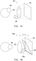
- Fig. 1A which shows a conventional eye tracking mechanism.
- the position of the camera 106 of the direct-view type eye tracker at the boundary of the lens 102 is getting more and more difficult to capture the eye feature (e.g., the pupil) when the target eye 199 is in some specific eye rotation angles.
- the display 104 of the chamber 100 which may be referred to as a VR tube
- the target eye 199 of the wearer may attempt to look at those objects.
- the target eye 199 may rotate upward such that the camera 106 disposed near the lower boundary of the lens 102 cannot retrieve eye images with pupils, and hence the related eye tracking mechanism cannot be properly performed.
- Fig. 1B which shows a hot-mirror type eye tracking mechanism.
- the camera 106 for capturing eye images of the target eye 199 is disposed inside of the chamber 100a, wherein the chamber 100a is further disposed with a mirror 108 that is only capable of reflecting infrared (IR) lights.
- the HMD may be disposed with an IR illuminator for illuminating the target eye 199 with IR lights, such that the target eye 199 may reflect the IR lights to the mirror 108.
- the mirror 108 As the mirror 108 receives the IR lights reflected by the target eye 199, the mirror 108 would further reflect the received IR lights to the camera 106a for the camera 106a to capture eye images of the target eye 199, such that the subsequent eye tracking mechanism may be performed.
- the thickness of the chamber 100a i.e., the VR tube
- the mirror 108 would be more and more closer to the display 104, and hence the visibility of the camera 106a is also getting smaller and smaller.
- US 2016/0366399 A1 discloses a head-mounted display system including a left lens for a user's left eye and a right lens for a user's right eye.
- the head-mounted display system also includes left and right display screens.
- the left display screen is coupled to the left lens to provide images to the user's left eye through the left lens.
- the right display screen is coupled to the right lens to provide images to the user's right eye through the right lens.
- US 4145122 A discloses an apparatus for monitoring the position of the eye and generating an electrical signal based upon its displacement from a neutral position, wherein a pair of eyeglasses modified to provide an infrared mirror on the inside surface of one lens, an infrared light emitting diode located on the nosepiece in position to produce a virtual image thereof within the wearer's eye as reflected from the infrared mirror, and an image detector mounted on the bow of the eyeglasses adjacent the mirror filtered to respond only to infrared light and effective to locate the position within the eye of the reflected LED image.
- US 2017/0031435 A1 discloses a lens having an IR-reflective coating that is selectively applied to form a variable infrared (IR) interaction pattern on the lens.
- the variable IR interaction pattern varies in the manner it interacts with IR wavelengths, so as to provide a machine-readable code when the lens is illuminated by IR light. Accordingly, variable IR interaction patterns is used to identify particular lenses.
- a glasses-style, modular, head-mountable device identifies which of a number of different possible lenses are currently attached to the HMD, and updates certain processes according to the lens or lenses is or are attached. For example, an HMD calibrates an eye-tracking process according to the particular lens that is attached.
- WO 2016/077258 A1 discloses an eye movement tracking device mounted to standard eyeglasses.
- the device comprises an illumination source, a time-of-flight (TOF) camera and a processor.
- the source transmits energy within a frequency band from a location proximate to an eye of a person, such that at least a first portion of the transmitted energy is reflected off a lens of eyewear worn by the person to subsequently reflect off the eye, and such that at least a second portion of the transmitted energy is transmitted through the lens to reflect off objects in the person's environment.
- the TOF camera detects reflections of at least the first portion of the transmitted energy, and distinguishes them from other energy detected by the TOF camera in said frequency band, based on TOF principles.
- the processor uses the detected reflections of the first portion of the transmitted energy to determine eye position.
- the present disclosure is directed to an HMD that could solve the above technical problems.
- the disclosure provides a head-mounted display (HMD) including a chamber a light emitter, a camera, and a processor.
- the chamber is disposed with a lens and a display, wherein the lens has a first surface and a second surface, the first surface faces the display, the second surface is coated with a reflective layer and faces a target eye of a wearer, and the reflective layer has at least one specific location.
- HMD head-mounted display
- the light emitter is located outside of the chamber and emits a first light to each specific location on the reflective layer, wherein for an i-th specific location of the at least one specific location, the first light is scattered as a plurality of second lights by the i-th specific location, the second lights are scattered as a plurality of third lights by the target eye, and the third lights are scattered as a plurality of fourth lights by a plurality of reference locations on the reflective layer;.
- the camera is located outside of the chamber and captures the fourth lights as an image corresponding to the i-th specific location.
- the processor is coupled with the light emitter and the camera and estimates an eye pose of the target eye based on the image corresponding to each specific location.
- the disclosure provides a head-mounted display (HMD) including a chamber, a reference light source, at least one light emitter, a camera, and a processor.
- the chamber is disposed with a lens and a display, wherein the lens has a first surface and a second surface, the first surface faces the display, and the second surface is coated with a reflective layer and faces a target eye of a wearer.
- the reference light source is located outside of the chamber and emits a reference light to the reflective layer.
- the at least one light emitter is located outside of the chamber and sequentially emits a first light to the target eye, wherein for an j-th light emitter of the at least one light emitter, the target eye scatters the first light corresponding to the j-th light emitter as a plurality of second lights to the reflective layer, the first light corresponding to each light emitter is temporally coherent to the reference light, and the second lights corresponding to the j-th light emitter interferes with the reference light as an interference pattern corresponding to the j-th light emitter.
- the camera is located outside of the chamber and captures the interference pattern corresponding to each light emitter.
- the processor is coupled with the reference light source, the at least on light emitter, and the camera and estimates an eye pose of the target eye based on the interference pattern corresponding to each light emitter.
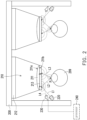
- the HMD 200 includes a chamber 210, a light emitter 220, a camera 230, and a processor 240.
- the chamber 210 is disposed with a lens 211 and a display 212, wherein the lens 211 has a first surface 211a and a second surface 211b.
- the display 212 may be used to provide a visual content (e.g., VR contents), and the visual content may be propagated through the lens 211 to a target eye 299 of a wearer of the HMD 200. That is, the target eye 299 may see the visual content through the lens 211.
- a visual content e.g., VR contents
- the first surface 211a faces the display 212
- the second surface 211b is coated with a reflective layer 213 and faces the target eye 299.
- the light emitter 220 is located outside of the chamber 210 and emits a first light L1 to the reflective layer 213.
- the reflective layer 213 may have at least one specific location, and the light emitter 220 may be designed to emit the first light L1 to each specific location on the reflective layer 213.
- Fig. 2 may be regarded as showing the situation of the light emitter 220 emitting the first light L1 to one specific location (denoted as v) on the reflective layer 213, but the disclosure is not limited thereto.
- the reflective layer 213 may include N specific locations and a plurality of reference locations.
- the N specific locations may be respectively denoted as v1, v2, ..., vN, and the specific location v in Fig. 2 may be understood as one of the N specific locations, but the disclosure is not limited thereto.
- the reference location k in Fig. 2 may be understood as one of the reference locations, but the disclosure is not limited thereto.
- the first light L1 may be a non-visible and narrowband light (e.g., an IR light) that has a wavelength distribution
- the reflective layer 213 may be designed to only scatter lights with a specific wavelength within the wavelength distribution, e.g., the first light L1.
- the first light L1 after the first light L1 reaches an i-th (1 ⁇ i ⁇ N) specific location (e.g., the specific location v) on the reflective layer 213, the first light L1 is scattered as a plurality of second lights by the i-th specific location, the second lights are scattered as a plurality of third lights by the target eye 299, and the third lights are scattered as a plurality of fourth lights by the reference locations on the reflective layer 213.
- the first light L1 may be regarded as being scattered as a plurality of second lights L2 (wherein only one of the second lights L2 is shown in Fig. 2 for brevity) by the specific location v on the reflective layer 213.
- the second lights L2 corresponding to the specific location v may be regarded as being scattered as a plurality of third lights L3 (wherein only one of the third lights L3 is shown in Fig. 2 for brevity) by a plurality of eye locations p (wherein only one of the eye locations p is shown in Fig. 2 for brevity) on the target eye 299.
- the third lights L3 corresponding to the specific location v may be regarded as being scattered as a plurality of fourth lights L4 (wherein only one of the fourth lights L4 is shown in Fig. 2 for brevity) corresponding to the specific location v by the reference locations on the reflective layer 213, but the disclosure is not limited thereto.
- the radiance generated by the third lights L3 at the reference location k may be modelled as: L k ⁇ ⁇ p f p ⁇ v , k ⁇ p L v cos p ⁇ v , n x dS p r pv 2 , wherein f represents the bidirectional reflectance distribution function (BRDF) at the point p, L(v) is the radiance at the point v, L(k) is the radiance at the reference location k, n x is the surface normal of the incident surface at p, dS p is the differential surface element near the point p, r pv is the distance from the specific location v to the eye location p, and the BRDF at the eye location p encoded the information of the target eye 299.
- BRDF bidirectional reflectance distribution function
- the camera 230 may be located outside of the chamber 210 and only capable of detecting lights with the specific wavelength (e.g., the fourth lights L4). In this case, the camera 230 may capture the fourth lights L4 as an image corresponding to the specific location v.
- the specific wavelength e.g., the fourth lights L4
- the radiance on a pixel q at the image corresponding to the specific location v may be modelled as: b q ⁇ ⁇ ⁇ ⁇ ⁇ ⁇ k K ⁇ t T L k cos n k , k ⁇ c dkd ⁇ q dt , and the details thereof may be also referred to the Document D1, which would not be repeated herein.
- the camera 230 may capture the image corresponding to each of the specific locations. That is, the camera 230 may capture N images (represented as I v 1 ,I v 2 ,..., I vN ) respectively corresponding to the N specific locations (i.e., v1-vN), but the disclosure is not limited thereto.
- the processor 240 coupled with the light emitter 220 and the camera 230 may estimate an eye pose of the target eye 299 based on the image corresponding to each specific location. That is, the processor 240 may estimate the eye pose of the target eye 299 based on the N images (i.e., I v 1 , I v 2 , I vN ).
- the processor 240 may input the image corresponding to each specific location to a feature extracting model. That is, the processor 240 may input I v 1 , I v 2 ,..., I vN to the feature extracting model.
- the feature extracting model may extract a plurality of 3D eye features of the target eye 299 from the image corresponding to each specific location.
- I v 1 , I v 2 ,..., I vN may be understood as a series of encoded images of the target eye 299 from different incident rays on the specific location v.
- the feature extracting model may include an encoder-decoder convolutional neural network which was trained to learn to predict the 3D eye features within the target eye 299 from I v 1 , I v 2 ,... , I vN (i.e., the encoded images), but the disclosure is not limited thereto.
- the 3D eye features extracted from the series of the radiance images may be characterized as a tensor, and the dimension of the (output) tensor characterizing the 3D eye feature extracted from I v 1 , I v 2 ,..., I vN may be WxHxC, wherein W may be the width of I v 1 and H may be the height of I v 1 .
- C may be a predetermined number of the feature index, which may be also regarded as the number of channels of the output tensor. That is, the tensor may be regarded as including C channels, wherein the channels one-to-one correspond to the 3D eye feature, and each channel is a WxH matrix.
- the i-th channel indicates the depth map corresponding i-th eye feature, wherein the value of this matrix element of in the channel indicates the depth step in a defined range.
- the processor 240 may obtain the eye pose of the target eye 299 based on the 3D eye features and 3D to 2D matching technique like PNP... etc.
- the processor 240 may reconstruct the 3D eye structure of the target eye 299 based on the 3D eye features, and the processor 240 may use a pose estimator to estimate the eye pose of the target eye 299 based on the reconstructed 3D eye structure.
- the pose estimator may be pre-trained to output an estimated eye pose based on the reconstructed eye structure, but the disclosure is not limited thereto.
- the processor 240 may further obtain a gaze direction of the target eye 299 based on the eye pose of the target eye 299, such that the eye tracking mechanism may be properly performed.
- the HMD 200 may include another chamber as shown in Fig. 2 , in which the teachings in the above may be used to obtain the eye pose of the other target eye of the wearer, and the details would not be repeated herein.
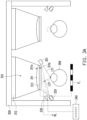
- the HMD 300 includes a chamber 300, a reference light source 320, light emitters 351-358, a camera 330, and a processor 340.
- the chamber 310 is disposed with a lens 311 and a display 312, wherein the lens 311 has a first surface 311a and a second surface 311b.
- the first surface 311a faces the display 312, and the second surface 311b is coated with a reflective layer 313 and faces a target eye 399 of a wearer of the HMD 300.
- the reference light source 320 is located outside of the chamber 310 and emits a reference light RL to the reflective layer 313.
- the reference light RL may be an IR light, but the disclosure is not limited thereto.
- the light emitters 351-358 are located outside of the chamber 310 and sequentially emits a first light L11 to the target eye 399, wherein the first light L11 corresponding to each light emitter 351-358 is temporally coherent to the reference light RL.
- the first light L1 1 may be a non-visible and narrowband light (e.g., an IR light) that has a wavelength distribution
- the reflective layer 313 may be designed to only scatter lights with a specific wavelength within the wavelength distribution, e.g., the first light L11.
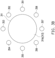
- the light emitters 351-358 may be disposed around the lens 313, but the disclosure is not limited thereto.
- the number and the position of each light emitter may be adjusted based on the requirements of the designer. For example, the number of the light emitters may be more or less, and the position of each light emitter may be varied as long as the first light L11 emitted by each light emitter may reach the target eye 399, but the disclosure is not limited thereto. It should be noted that only the light emitter 351 is shown in Fig. 3A for simplifying the illustration, but the disclosure is not limited thereto.
- the target eye 399 may scatter the first light corresponding to the j-th light emitter as a plurality of second lights to the reflective layer 313.
- the target eye 399 may scatter the first light L11 corresponding to the light emitter 351 as the second lights L21 (wherein only one of the second lights L21 is shown in Fig. 3A for brevity) to the reflective layer 313.
- the first light L11 corresponding thereto would be scattered by the target eye 399 to the reflective layer 313 as well.
- the second lights corresponding to each light emitter 351-358 would interfere with the reference light RL as an interference pattern corresponding to each light emitter 351-358.
- the second lights L21 corresponding to the light emitter 351 would interfere with the reference light RL as an interference pattern P 1 corresponding to the light emitter 351. Therefore, after the light emitters 351-358 sequentially emits the first light L11, there would be eight (i.e., the number of the light emitters 351-358) interference patterns (referred to as P 1 - P 8 ) that could be observed on the reflective layer 313.
- the camera 330 may be located outside of the chamber 310 and only capable of detecting lights with the specific wavelength. In this case, the camera 330 may capture the interference pattern corresponding to each light emitter 351-358. That is, in the scenario of Fig. 3A and Fig. 3B , the camera 330 may capture P 1 - P 8 .
- the processor 340 coupled with the reference light source 320, the light emitter 351-358, and the camera 330 may estimate an eye pose of the target eye 399 based on the interference pattern corresponding to each light emitter 351-358. That is, the processor 340 may estimate an eye pose of the target eye 399 based on P 1 - P 8 .
- the processor 340 may input the interference pattern corresponding to each light emitter 351-358 to a feature extracting model. That is, the processor 340 may input P 1 -P 8 to the feature extracting model.
- the feature extracting model may extract a plurality of 3D eye features of the target eye 399 from the interference pattern corresponding to each light emitter 351-358.
- P 1 - P 8 may be understood as encoded multi-view images of the target eye 399.
- the feature extracting model may include an encoder-decoder convolutional neural network pre-trained to learn to extract the 3D eye features within the target eye 399 from P 1 - P 8 (i.e., the encoded multi-view images), but the disclosure is not limited thereto.
- the 3D eye features extracted from one of the interference pattern may be characterized as a tensor, and the details thereof may be referred to the teachings in the first embodiment, which would not be repeated herein.
- the processor 340 may obtain the eye pose of the target eye 399 based on the 3D eye features.
- the processor 340 may reconstruct the 3D eye structure of the target eye 399 based on the input interference images, and the processor 340 may use a pose estimator to estimate the eye pose of the target eye 399 based on the reconstructed 3D eye structure.
- the pose estimator may be pre-trained to output an estimated eye pose based on the reconstructed eye structure, but the disclosure is not limited thereto.
- the processor 340 may further obtain a gaze direction of the target eye 399 based on the eye pose of the target eye 399, such that the eye tracking mechanism may be properly performed.
- the HMD 300 may include another chamber as shown in Fig. 3A , in which the teachings in the above may be used to obtain the eye pose of the other target eye of the wearer, and the details would not be repeated herein.
- the disclosure provides two HMD structures in which a reflective layer is coated on the lens surface facing the target eye of the wearer.
- the two proposed HMD structures may be used to perform the eye tracking mechanisms in a novel way, such that the eye tracking mechanisms would not be limited by the chamber with small thickness or limited by the situation where the target eye performs extreme rotations (e.g., looking at the objects at the boundary of the visual content).
Landscapes
- Physics & Mathematics (AREA)
- Engineering & Computer Science (AREA)
- General Physics & Mathematics (AREA)
- Optics & Photonics (AREA)
- General Engineering & Computer Science (AREA)
- Theoretical Computer Science (AREA)
- Human Computer Interaction (AREA)
Claims (15)
- Eine kopfgetragene Anzeige, HMD, umfassend:eine Kammer (210), die mit einer Linse (211) und einer Anzeige (212) angeordnet ist, wobei die Linse eine erste Oberfläche (211a) und eine zweite Oberfläche (211b) aufweist, wobei die erste Oberfläche der Anzeige zugewandt ist, wobei die zweite Oberfläche mit einer reflektierenden Schicht (213) beschichtet ist und einem Zielauge (299) eines Trägers zugewandt ist, und wobei die reflektierende Schicht mehr als eine spezifische Stelle aufweist;einen Lichtemitter (220), der sich außerhalb der Kammer befindet und ein erstes Licht zu jeder spezifischen Stelle auf der reflektierenden Schicht emittiert, wobei für eine i-te spezifische Stelle der mindestens einen spezifischen Stelle das erste Licht als eine Mehrzahl von zweiten Lichtern durch die i-te spezifische Stelle gestreut wird, wobei die zweiten Lichter als eine Mehrzahl von dritten Lichtern durch das Zielauge gestreut werden, und wobei die dritten Lichter als eine Mehrzahl von vierten Lichtern durch eine Mehrzahl von Referenzstellen auf der reflektierenden Schicht gestreut werden;eine Kamera (230), die sich außerhalb der Kammer befindet und das vierte Licht als ein Bild aufnimmt, das der i-ten spezifischen Stelle entspricht; undeinen Prozessor (240), der mit dem Lichtemitter und der Kamera gekoppelt ist und eine Augenstellung des Zielauges auf der Grundlage des Bildes, das jeder spezifischen Position entspricht, schätzt.
- HMD nach Anspruch 1, wobei die Anzeige dazu verwendet wird, einen visuellen Inhalt bereitzustellen, wobei der visuelle Inhalt durch die Linse an das Zielauge weitergeleitet wird.
- HMD nach Anspruch 1, wobei das erste Licht ein schmalbandiges Licht mit einer Wellenlängenverteilung ist, wobei die reflektierende Schicht nur Licht mit einer bestimmten Wellenlänge innerhalb der Wellenlängenverteilung streut, und wobei die Kamera nur Licht mit der bestimmten Wellenlänge aufnimmt.
- HMD nach Anspruch 1, wobei der Prozessor konfiguriert ist zum:Eingeben des Bildes, das jeder spezifischen Stelle entspricht, in ein Merkmalsextraktionsmodell, wobei das Merkmalsextraktionsmodell eine Vielzahl von 3D-Augenmerkmalen des Zielauges aus dem Bild, das jeder spezifischen Stelle entspricht, extrahiert; undErmitteln der Augenposition des Zielauges auf der Grundlage der 3D-Augenmerkmale.
- HMD nach Anspruch 4, wobei das Merkmalsextraktionsmodell ein Kodierer-Dekodierer-Faltungsneuronennetzwerk umfasst.
- HMD nach Anspruch 1, wobei das erste Licht ein nicht sichtbares Licht ist.
- HMD nach Anspruch 1, wobei der Prozessor ferner eine Blickrichtung des Zielauges auf der Grundlage der Augenstellung des Zielauges ermittelt.
- Eine kopfgetragene Anzeige, HMD, umfassend:eine Kammer (310), die mit einer Linse (311) und einer Anzeige (312) angeordnet ist, wobei die Linse eine erste Oberfläche (311a) und eine zweite Oberfläche (311b) aufweist, wobei die erste Oberfläche der Anzeige zugewandt ist und die zweite Oberfläche mit einer streuenden reflektierenden Schicht (313) beschichtet ist und einem Zielauge (399) eines Trägers zugewandt ist;eine Referenzlichtquelle (320), die sich außerhalb der Kammer befindet und ein Referenzlicht auf die reflektierende Schicht aussendet;mindestens einen Lichtemitter (351), der außerhalb der Kammer angeordnet ist und sequentiell ein erstes Licht auf das Zielauge emittiert, wobei für einen j-ten Lichtemitter des mindestens einen Lichtemitters das Zielauge das dem j-ten Lichtemitter entsprechende erste Licht als eine Vielzahl von zweiten Lichtern auf die reflektierende Schicht streut, wobei das jedem Lichtemitter entsprechende erste Licht zeitlich kohärent mit dem Referenzlicht ist, und wobei das dem j-ten Lichtemitter entsprechende zweite Licht mit dem Referenzlicht als ein dem j-ten Lichtemitter entsprechendes Interferenzmuster interferiert;eine Kamera (330), die sich außerhalb der Kammer befindet und das jedem Lichtemitter entsprechende Interferenzmuster aufnimmt; undeinen Prozessor (340), der mit der Referenzlichtquelle, dem mindestens einen Lichtemitter und der Kamera gekoppelt ist und eine Augenstellung des Zielauges auf der Grundlage des jedem Lichtemitter entsprechenden Interferenzmusters abschätzt.
- HMD nach Anspruch 8, wobei die Anzeige dazu verwendet wird, einen visuellen Inhalt bereitzustellen, wobei der visuelle Inhalt durch die Linse zum Zielauge übertragen wird.
- HMD nach Anspruch 8, wobei das erste Licht eine Wellenlängenverteilung aufweist, wobei die reflektierende Schicht nur Licht mit einer bestimmten Wellenlänge innerhalb der Wellenlängenverteilung streut, und wobei die Kamera nur Licht mit der bestimmten Wellenlänge aufnimmt.
- HMD nach Anspruch 8, wobei der Prozessor konfiguriert ist zum:Eingeben des jedem Lichtemitter entsprechenden Interferenzmusters in ein Merkmalsextraktionsmodell, wobei das Merkmalsextraktionsmodell eine Vielzahl von 3D-Augenmerkmalen des Zielauges aus dem jedem Lichtemitter entsprechenden Interferenzmuster extrahiert; undErmitteln der Augenposition des Zielauges auf der Grundlage der 3D-Augenmerkmale.
- HMD nach Anspruch 11, wobei das Merkmalsextraktionsmodell ein Kodierer-Dekodierer-Faltungsneuronalnetzwerk umfasst.
- HMD nach Anspruch 8, wobei der mindestens eine Lichtemitter um die Linse herum angeordnet ist.
- HMD nach Anspruch 8, wobei das erste Licht ein nicht sichtbares Licht ist.
- HMD nach Anspruch 8, wobei der Prozessor ferner eine Blickrichtung des Zielauges auf der Grundlage der Augenstellung des Zielauges ermittelt.
Applications Claiming Priority (1)
| Application Number | Priority Date | Filing Date | Title |
|---|---|---|---|
| US201962885827P | 2019-08-13 | 2019-08-13 |
Publications (3)
| Publication Number | Publication Date |
|---|---|
| EP3779561A1 EP3779561A1 (de) | 2021-02-17 |
| EP3779561C0 EP3779561C0 (de) | 2024-08-14 |
| EP3779561B1 true EP3779561B1 (de) | 2024-08-14 |
Family
ID=72086750
Family Applications (1)
| Application Number | Title | Priority Date | Filing Date |
|---|---|---|---|
| EP20190901.7A Active EP3779561B1 (de) | 2019-08-13 | 2020-08-13 | Kopfmontierte anzeige |
Country Status (4)
| Country | Link |
|---|---|
| US (1) | US11327318B2 (de) |
| EP (1) | EP3779561B1 (de) |
| CN (1) | CN112394515B (de) |
| TW (1) | TWI751647B (de) |
Families Citing this family (2)
| Publication number | Priority date | Publication date | Assignee | Title |
|---|---|---|---|---|
| EP3779561B1 (de) * | 2019-08-13 | 2024-08-14 | HTC Corporation | Kopfmontierte anzeige |
| CN112416125A (zh) * | 2020-11-17 | 2021-02-26 | 青岛小鸟看看科技有限公司 | Vr头戴式一体机 |
Family Cites Families (22)
| Publication number | Priority date | Publication date | Assignee | Title |
|---|---|---|---|---|
| US4145122A (en) * | 1977-05-31 | 1979-03-20 | Colorado Seminary | Method and apparatus for monitoring the position of the eye |
| US4848340A (en) * | 1988-02-10 | 1989-07-18 | Intelligent Surgical Lasers | Eyetracker and method of use |
| JPH02164335A (ja) * | 1988-12-16 | 1990-06-25 | Konan Camera Kenkyusho:Kk | 眼球運動解析装置 |
| DE102004055683B4 (de) * | 2004-10-26 | 2006-09-07 | Carl Zeiss Surgical Gmbh | Augenchirurgie-Mikroskopiesystem und Verfahren hierzu |
| US9298007B2 (en) * | 2014-01-21 | 2016-03-29 | Osterhout Group, Inc. | Eye imaging in head worn computing |
| US8398239B2 (en) * | 2009-03-02 | 2013-03-19 | Honeywell International Inc. | Wearable eye tracking system |
| US8955973B2 (en) * | 2012-01-06 | 2015-02-17 | Google Inc. | Method and system for input detection using structured light projection |
| US9208566B2 (en) * | 2013-08-09 | 2015-12-08 | Microsoft Technology Licensing, Llc | Speckle sensing for motion tracking |
| US9292765B2 (en) * | 2014-01-07 | 2016-03-22 | Microsoft Technology Licensing, Llc | Mapping glints to light sources |
| US9532715B2 (en) * | 2014-01-21 | 2017-01-03 | Osterhout Group, Inc. | Eye imaging in head worn computing |
| US9454699B2 (en) * | 2014-04-29 | 2016-09-27 | Microsoft Technology Licensing, Llc | Handling glare in eye tracking |
| US9568603B2 (en) * | 2014-11-14 | 2017-02-14 | Microsoft Technology Licensing, Llc | Eyewear-mountable eye tracking device |
| US10085004B2 (en) * | 2015-06-15 | 2018-09-25 | Oculus Vr, Llc | Dual-screen head-mounted displays |
| US9870049B2 (en) * | 2015-07-31 | 2018-01-16 | Google Llc | Reflective lenses to auto-calibrate a wearable system |
| US9904051B2 (en) * | 2015-10-23 | 2018-02-27 | Thalmic Labs Inc. | Systems, devices, and methods for laser eye tracking |
| US9983709B2 (en) * | 2015-11-02 | 2018-05-29 | Oculus Vr, Llc | Eye tracking using structured light |
| US10013055B2 (en) * | 2015-11-06 | 2018-07-03 | Oculus Vr, Llc | Eye tracking using optical flow |
| US10466491B2 (en) * | 2016-06-01 | 2019-11-05 | Mentor Acquisition One, Llc | Modular systems for head-worn computers |
| USD864959S1 (en) * | 2017-01-04 | 2019-10-29 | Mentor Acquisition One, Llc | Computer glasses |
| US10725537B2 (en) * | 2017-10-02 | 2020-07-28 | Facebook Technologies, Llc | Eye tracking system using dense structured light patterns |
| US10861225B2 (en) * | 2018-08-10 | 2020-12-08 | Intel Corporation | Neural network processing for multi-object 3D modeling |
| EP3779561B1 (de) * | 2019-08-13 | 2024-08-14 | HTC Corporation | Kopfmontierte anzeige |
-
2020
- 2020-08-13 EP EP20190901.7A patent/EP3779561B1/de active Active
- 2020-08-13 US US16/992,118 patent/US11327318B2/en active Active
- 2020-08-13 CN CN202010810927.7A patent/CN112394515B/zh active Active
- 2020-08-13 TW TW109127479A patent/TWI751647B/zh active
Also Published As
| Publication number | Publication date |
|---|---|
| EP3779561C0 (de) | 2024-08-14 |
| TW202107152A (zh) | 2021-02-16 |
| CN112394515B (zh) | 2022-06-07 |
| US11327318B2 (en) | 2022-05-10 |
| US20210048675A1 (en) | 2021-02-18 |
| EP3779561A1 (de) | 2021-02-17 |
| TWI751647B (zh) | 2022-01-01 |
| CN112394515A (zh) | 2021-02-23 |
Similar Documents
| Publication | Publication Date | Title |
|---|---|---|
| US12436395B2 (en) | Optical configurations for head-worn see-through displays | |
| EP4066481B1 (de) | Parallaxenkorrektur mittels kameras verschiedener modalitäten | |
| US10437327B2 (en) | Eye tracking device and method for operating an eye tracking device | |
| US11675429B2 (en) | Calibration, customization, and improved user experience for bionic lenses | |
| EP3371781B1 (de) | Systeme und verfahren zur erzeugung und verwendung dreidimensionaler abbildungen | |
| CN107250882A (zh) | 用于头戴式计算的电源管理 | |
| CN119234201A (zh) | 基于光源遮挡的动态视觉传感器跟踪 | |
| JP7833566B2 (ja) | 同期動的視覚センサled ai追跡システム及び方法 | |
| EP3779561B1 (de) | Kopfmontierte anzeige | |
| US11182631B2 (en) | Information processing method and electronic device | |
| CN119278353A (zh) | 异步动态视觉传感器led ai跟踪系统和方法 | |
| JP7833565B2 (ja) | 動的視覚センサに基づいた目及び/または顔の追跡 | |
| CN117215401A (zh) | 使用ir和环境光的混合像素动态视觉传感器跟踪 | |
| JP7835896B2 (ja) | コントローラの追跡および同時の身体追跡の方法、slamまたはセーフティシャッタにおける動的視覚センサハイブリッド素子の展開 | |
| US11768926B2 (en) | Method of textured contact lens detection | |
| WO2018164104A1 (ja) | 眼部画像処理装置 | |
| EP4587909A1 (de) | Verfolgungssystem mit einer differenzkamera | |
| US20240153136A1 (en) | Eye tracking | |
| US12013528B1 (en) | Optimised tracking camera positioning in display devices | |
| JP2023040887A (ja) | 個人認証装置及び個人認証方法、プログラム |
Legal Events
| Date | Code | Title | Description |
|---|---|---|---|
| PUAI | Public reference made under article 153(3) epc to a published international application that has entered the european phase |
Free format text: ORIGINAL CODE: 0009012 |
|
| STAA | Information on the status of an ep patent application or granted ep patent |
Free format text: STATUS: EXAMINATION IS IN PROGRESS |
|
| 17P | Request for examination filed |
Effective date: 20200813 |
|
| AK | Designated contracting states |
Kind code of ref document: A1 Designated state(s): AL AT BE BG CH CY CZ DE DK EE ES FI FR GB GR HR HU IE IS IT LI LT LU LV MC MK MT NL NO PL PT RO RS SE SI SK SM TR |
|
| AX | Request for extension of the european patent |
Extension state: BA ME |
|
| RBV | Designated contracting states (corrected) |
Designated state(s): AL AT BE BG CH CY CZ DE DK EE ES FI FR GB GR HR HU IE IS IT LI LT LU LV MC MK MT NL NO PL PT RO RS SE SI SK SM TR |
|
| GRAP | Despatch of communication of intention to grant a patent |
Free format text: ORIGINAL CODE: EPIDOSNIGR1 |
|
| STAA | Information on the status of an ep patent application or granted ep patent |
Free format text: STATUS: GRANT OF PATENT IS INTENDED |
|
| RIN1 | Information on inventor provided before grant (corrected) |
Inventor name: LIN, YUNG-CHEN |
|
| INTG | Intention to grant announced |
Effective date: 20240326 |
|
| RAP3 | Party data changed (applicant data changed or rights of an application transferred) |
Owner name: HTC CORPORATION |
|
| GRAS | Grant fee paid |
Free format text: ORIGINAL CODE: EPIDOSNIGR3 |
|
| GRAA | (expected) grant |
Free format text: ORIGINAL CODE: 0009210 |
|
| STAA | Information on the status of an ep patent application or granted ep patent |
Free format text: STATUS: THE PATENT HAS BEEN GRANTED |
|
| AK | Designated contracting states |
Kind code of ref document: B1 Designated state(s): AL AT BE BG CH CY CZ DE DK EE ES FI FR GB GR HR HU IE IS IT LI LT LU LV MC MK MT NL NO PL PT RO RS SE SI SK SM TR |
|
| REG | Reference to a national code |
Ref country code: GB Ref legal event code: FG4D |
|
| REG | Reference to a national code |
Ref country code: CH Ref legal event code: EP |
|
| REG | Reference to a national code |
Ref country code: DE Ref legal event code: R096 Ref document number: 602020035643 Country of ref document: DE |
|
| REG | Reference to a national code |
Ref country code: IE Ref legal event code: FG4D |
|
| U01 | Request for unitary effect filed |
Effective date: 20240904 |
|
| U07 | Unitary effect registered |
Designated state(s): AT BE BG DE DK EE FI FR IT LT LU LV MT NL PT RO SE SI Effective date: 20240924 |
|
| PG25 | Lapsed in a contracting state [announced via postgrant information from national office to epo] |
Ref country code: NO Free format text: LAPSE BECAUSE OF FAILURE TO SUBMIT A TRANSLATION OF THE DESCRIPTION OR TO PAY THE FEE WITHIN THE PRESCRIBED TIME-LIMIT Effective date: 20241114 |
|
| PG25 | Lapsed in a contracting state [announced via postgrant information from national office to epo] |
Ref country code: GR Free format text: LAPSE BECAUSE OF FAILURE TO SUBMIT A TRANSLATION OF THE DESCRIPTION OR TO PAY THE FEE WITHIN THE PRESCRIBED TIME-LIMIT Effective date: 20241115 Ref country code: PL Free format text: LAPSE BECAUSE OF FAILURE TO SUBMIT A TRANSLATION OF THE DESCRIPTION OR TO PAY THE FEE WITHIN THE PRESCRIBED TIME-LIMIT Effective date: 20240814 |
|
| PG25 | Lapsed in a contracting state [announced via postgrant information from national office to epo] |
Ref country code: IS Free format text: LAPSE BECAUSE OF FAILURE TO SUBMIT A TRANSLATION OF THE DESCRIPTION OR TO PAY THE FEE WITHIN THE PRESCRIBED TIME-LIMIT Effective date: 20241214 |
|
| PG25 | Lapsed in a contracting state [announced via postgrant information from national office to epo] |
Ref country code: HR Free format text: LAPSE BECAUSE OF FAILURE TO SUBMIT A TRANSLATION OF THE DESCRIPTION OR TO PAY THE FEE WITHIN THE PRESCRIBED TIME-LIMIT Effective date: 20240814 |
|
| PG25 | Lapsed in a contracting state [announced via postgrant information from national office to epo] |
Ref country code: ES Free format text: LAPSE BECAUSE OF FAILURE TO SUBMIT A TRANSLATION OF THE DESCRIPTION OR TO PAY THE FEE WITHIN THE PRESCRIBED TIME-LIMIT Effective date: 20240814 Ref country code: RS Free format text: LAPSE BECAUSE OF FAILURE TO SUBMIT A TRANSLATION OF THE DESCRIPTION OR TO PAY THE FEE WITHIN THE PRESCRIBED TIME-LIMIT Effective date: 20241114 |
|
| PG25 | Lapsed in a contracting state [announced via postgrant information from national office to epo] |
Ref country code: RS Free format text: LAPSE BECAUSE OF FAILURE TO SUBMIT A TRANSLATION OF THE DESCRIPTION OR TO PAY THE FEE WITHIN THE PRESCRIBED TIME-LIMIT Effective date: 20241114 Ref country code: PL Free format text: LAPSE BECAUSE OF FAILURE TO SUBMIT A TRANSLATION OF THE DESCRIPTION OR TO PAY THE FEE WITHIN THE PRESCRIBED TIME-LIMIT Effective date: 20240814 Ref country code: NO Free format text: LAPSE BECAUSE OF FAILURE TO SUBMIT A TRANSLATION OF THE DESCRIPTION OR TO PAY THE FEE WITHIN THE PRESCRIBED TIME-LIMIT Effective date: 20241114 Ref country code: IS Free format text: LAPSE BECAUSE OF FAILURE TO SUBMIT A TRANSLATION OF THE DESCRIPTION OR TO PAY THE FEE WITHIN THE PRESCRIBED TIME-LIMIT Effective date: 20241214 Ref country code: HR Free format text: LAPSE BECAUSE OF FAILURE TO SUBMIT A TRANSLATION OF THE DESCRIPTION OR TO PAY THE FEE WITHIN THE PRESCRIBED TIME-LIMIT Effective date: 20240814 Ref country code: GR Free format text: LAPSE BECAUSE OF FAILURE TO SUBMIT A TRANSLATION OF THE DESCRIPTION OR TO PAY THE FEE WITHIN THE PRESCRIBED TIME-LIMIT Effective date: 20241115 Ref country code: ES Free format text: LAPSE BECAUSE OF FAILURE TO SUBMIT A TRANSLATION OF THE DESCRIPTION OR TO PAY THE FEE WITHIN THE PRESCRIBED TIME-LIMIT Effective date: 20240814 |
|
| PG25 | Lapsed in a contracting state [announced via postgrant information from national office to epo] |
Ref country code: SM Free format text: LAPSE BECAUSE OF FAILURE TO SUBMIT A TRANSLATION OF THE DESCRIPTION OR TO PAY THE FEE WITHIN THE PRESCRIBED TIME-LIMIT Effective date: 20240814 |
|
| PG25 | Lapsed in a contracting state [announced via postgrant information from national office to epo] |
Ref country code: CZ Free format text: LAPSE BECAUSE OF FAILURE TO SUBMIT A TRANSLATION OF THE DESCRIPTION OR TO PAY THE FEE WITHIN THE PRESCRIBED TIME-LIMIT Effective date: 20240814 |
|
| PG25 | Lapsed in a contracting state [announced via postgrant information from national office to epo] |
Ref country code: SK Free format text: LAPSE BECAUSE OF FAILURE TO SUBMIT A TRANSLATION OF THE DESCRIPTION OR TO PAY THE FEE WITHIN THE PRESCRIBED TIME-LIMIT Effective date: 20240814 |
|
| PLBE | No opposition filed within time limit |
Free format text: ORIGINAL CODE: 0009261 |
|
| STAA | Information on the status of an ep patent application or granted ep patent |
Free format text: STATUS: NO OPPOSITION FILED WITHIN TIME LIMIT |
|
| PGFP | Annual fee paid to national office [announced via postgrant information from national office to epo] |
Ref country code: GB Payment date: 20250619 Year of fee payment: 6 |
|
| 26N | No opposition filed |
Effective date: 20250515 |
|
| U20 | Renewal fee for the european patent with unitary effect paid |
Year of fee payment: 6 Effective date: 20250709 |
|
| REG | Reference to a national code |
Ref country code: CH Ref legal event code: H13 Free format text: ST27 STATUS EVENT CODE: U-0-0-H10-H13 (AS PROVIDED BY THE NATIONAL OFFICE) Effective date: 20260324 |
|
| PG25 | Lapsed in a contracting state [announced via postgrant information from national office to epo] |
Ref country code: MC Free format text: LAPSE BECAUSE OF FAILURE TO SUBMIT A TRANSLATION OF THE DESCRIPTION OR TO PAY THE FEE WITHIN THE PRESCRIBED TIME-LIMIT Effective date: 20240814 |
|
| PG25 | Lapsed in a contracting state [announced via postgrant information from national office to epo] |
Ref country code: CH Free format text: LAPSE BECAUSE OF NON-PAYMENT OF DUE FEES Effective date: 20250831 |
|
| U1N | Appointed representative for the unitary patent procedure changed after the registration of the unitary effect |
Representative=s name: MARKS & CLERK LLP; GB |