EP3779800B1 - Bilderkennungsverfahren, vorrichtung, elektronische vorrichtung und speichermedium - Google Patents
Bilderkennungsverfahren, vorrichtung, elektronische vorrichtung und speichermedium Download PDFInfo
- Publication number
- EP3779800B1 EP3779800B1 EP19778369.9A EP19778369A EP3779800B1 EP 3779800 B1 EP3779800 B1 EP 3779800B1 EP 19778369 A EP19778369 A EP 19778369A EP 3779800 B1 EP3779800 B1 EP 3779800B1
- Authority
- EP
- European Patent Office
- Prior art keywords
- matrix
- input
- matrices
- result
- output
- Prior art date
- Legal status (The legal status is an assumption and is not a legal conclusion. Google has not performed a legal analysis and makes no representation as to the accuracy of the status listed.)
- Active
Links
Images




Classifications
-
- G—PHYSICS
- G06—COMPUTING OR CALCULATING; COUNTING
- G06F—ELECTRIC DIGITAL DATA PROCESSING
- G06F17/00—Digital computing or data processing equipment or methods, specially adapted for specific functions
- G06F17/10—Complex mathematical operations
- G06F17/16—Matrix or vector computation, e.g. matrix-matrix or matrix-vector multiplication, matrix factorization
-
- G—PHYSICS
- G06—COMPUTING OR CALCULATING; COUNTING
- G06F—ELECTRIC DIGITAL DATA PROCESSING
- G06F18/00—Pattern recognition
- G06F18/20—Analysing
- G06F18/21—Design or setup of recognition systems or techniques; Extraction of features in feature space; Blind source separation
-
- G—PHYSICS
- G06—COMPUTING OR CALCULATING; COUNTING
- G06N—COMPUTING ARRANGEMENTS BASED ON SPECIFIC COMPUTATIONAL MODELS
- G06N3/00—Computing arrangements based on biological models
- G06N3/02—Neural networks
-
- G—PHYSICS
- G06—COMPUTING OR CALCULATING; COUNTING
- G06N—COMPUTING ARRANGEMENTS BASED ON SPECIFIC COMPUTATIONAL MODELS
- G06N3/00—Computing arrangements based on biological models
- G06N3/02—Neural networks
- G06N3/04—Architecture, e.g. interconnection topology
-
- G—PHYSICS
- G06—COMPUTING OR CALCULATING; COUNTING
- G06N—COMPUTING ARRANGEMENTS BASED ON SPECIFIC COMPUTATIONAL MODELS
- G06N3/00—Computing arrangements based on biological models
- G06N3/02—Neural networks
- G06N3/04—Architecture, e.g. interconnection topology
- G06N3/045—Combinations of networks
-
- G—PHYSICS
- G06—COMPUTING OR CALCULATING; COUNTING
- G06N—COMPUTING ARRANGEMENTS BASED ON SPECIFIC COMPUTATIONAL MODELS
- G06N3/00—Computing arrangements based on biological models
- G06N3/02—Neural networks
- G06N3/04—Architecture, e.g. interconnection topology
- G06N3/0464—Convolutional networks [CNN, ConvNet]
-
- G—PHYSICS
- G06—COMPUTING OR CALCULATING; COUNTING
- G06N—COMPUTING ARRANGEMENTS BASED ON SPECIFIC COMPUTATIONAL MODELS
- G06N3/00—Computing arrangements based on biological models
- G06N3/02—Neural networks
- G06N3/08—Learning methods
-
- G—PHYSICS
- G06—COMPUTING OR CALCULATING; COUNTING
- G06N—COMPUTING ARRANGEMENTS BASED ON SPECIFIC COMPUTATIONAL MODELS
- G06N3/00—Computing arrangements based on biological models
- G06N3/02—Neural networks
- G06N3/08—Learning methods
- G06N3/082—Learning methods modifying the architecture, e.g. adding, deleting or silencing nodes or connections
-
- G—PHYSICS
- G06—COMPUTING OR CALCULATING; COUNTING
- G06V—IMAGE OR VIDEO RECOGNITION OR UNDERSTANDING
- G06V10/00—Arrangements for image or video recognition or understanding
- G06V10/70—Arrangements for image or video recognition or understanding using pattern recognition or machine learning
-
- G—PHYSICS
- G06—COMPUTING OR CALCULATING; COUNTING
- G06V—IMAGE OR VIDEO RECOGNITION OR UNDERSTANDING
- G06V10/00—Arrangements for image or video recognition or understanding
- G06V10/70—Arrangements for image or video recognition or understanding using pattern recognition or machine learning
- G06V10/82—Arrangements for image or video recognition or understanding using pattern recognition or machine learning using neural networks
Definitions
- Embodiments of the disclosure relate to the field of image processing, and in particular, to an image recognition method, apparatus, electronic device, and storage medium thereof.
- intelligent image recognition services based on a convolutional neural network model for example, facial and gesture recognition provided by a mobile terminal, obstacle avoidance, and intelligent navigation provided by an embedded device, have been implemented on electronic devices of different types.
- WANG ZELONG ET AL "Winograd Algorithm for 3D convolution Neural Networks", 25 October 2017 (2017-10-25), ICIAP: INTERNATIONAL CONFERENCE ON IMAGE ANALYSIS AND PROCESSING, 17TH INTERNATIONAL CONFERENCE, NAPLES, ITALY, SEPTEMBER 9-13, 2013. PROCESSING; [LECTURE NOTES IN COMPUTER SCIENCE; LECT.NOTES COMPUTER], SPRING, BERLIN, HEIDELBERG, PAGE(S) 609-6, ISBN: 978-3-642-17318-9 reduces the algorithm complexity of 3D CNN to accelerate a model with Winograd's minimal algorithm.
- Embodiments of the disclosure provide an image recognition method, apparatus, electronic device, computer program and storage medium, to solve the above problems of low efficiency in an image recognition method in the related art.
- a storage medium according to the invention is recited in appended claim 14.
- a computer program according to the invention is recited in appended claim 13.
- F(2 ⁇ 2, 3 ⁇ 3) represents that an output matrix in the Winograd algorithm is a 2 ⁇ 2 matrix, and a convolution kernel matrix is a 3 ⁇ 3 matrix.
- the algorithm includes four key stages:
- d is an input matrix
- g is a convolution kernel matrix corresponding to the input matrix d
- B ⁇ G ⁇ A and B T ⁇ G T ⁇ A T are known parameter matrices
- V is an input transformation result matrix
- U is a convolution kernel transformation result matrix
- M is a to-be-outputted transformation matrix
- S is an output matrix.
- the multiplications performed on the input transformation result matrix V and the convolution kernel transformation result matrix U are defined as element-wise multiplications.
- the element-wise multiplication may be implemented by using a level-1 BLAS matrix operation, to reduce a computational volume.
- the level-1 BLAS matrix operation is essentially not suitable for an electronic device with a Von Neumann architecture. Therefore, although the computational volume is greatly reduced, computing efficiency is still low. Therefore, the advantage of reducing computational volume is offset, and, the speedup is not much improved.
- acceleration through a dedicated hardware not only has high implementation costs, but also has no compatibility.
- a model compression has a very high compression ratio on the premise that calculation precision is ensured, but still cannot effectively improve a speedup.
- embodiments of the disclosure specifically provides an efficient image recognition method. That is, an image recognition apparatus corresponding to the image recognition method that is applicable to an electronic device with a Von Neumann architecture, for example, a smartphone.
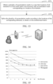
- FIG. 2 is a schematic diagram of an implementation environment of an image recognition method according to an embodiment.
- the implementation environment includes an electronic device 100 in which an image recognition apparatus is deployed, and a server end 200.
- the electronic device 100 may be a tablet computer, a palmtop computer, a smartphone, an unmanned aerial vehicle, a robot, a portable smart device (such as smart glasses or a smart camera), or the like. However, it is not limited thereto.
- the server end 200 establishes a communication connection to the electronic device 100 through a wireless network or a wired network, to implement data transmission with the electronic device 100 through the communication connection.
- a transmitted data packet includes a convolutional neural network model stored in a file form.
- the server end 200 may be a server, or may be a server cluster including a plurality of servers or a cloud computing center including a plurality of servers. However, it is not limited thereto.
- a model training of a convolutional neural network model is performed by using a large quantity of training samples, and the convolutional neural network model obtained through the training is stored in a file form and delivered to the electronic device 100.
- the electronic device 100 receives the convolutional neural network model that is in the file form and that is delivered by the server end 200, and further performs image recognition by using the convolutional neural network model, to provide a user with intelligent image recognition services such as facial recognition, gesture recognition, text recognition, obstacle avoidance, and intelligent navigation.
- intelligent image recognition services such as facial recognition, gesture recognition, text recognition, obstacle avoidance, and intelligent navigation.
- FIG. 3 is a block diagram of a hardware structure of an electronic device according to an embodiment.
- the electronic device is merely an example adapted to this disclosure, and cannot be considered as providing any limitation to a use range of this disclosure.
- the electronic device cannot be explained as needing to reply on or needing to have one or more components in the electronic device 100 shown in FIG. 3 .
- the electronic device 100 includes a memory 101, a storage controller 103, one or more (only one is shown in FIG. 3 ) processors 105, a peripheral interface 107, a camera module 113, a touchscreen 117, and a key module 119.
- the components communicate with each other through one or more communications buses/signal lines 121.
- the memory 101 may be configured to store a computer program and a module, for example, a computer-readable instruction and module corresponding to the image recognition method and apparatus in the embodiments, and the processor 105 may be configured to perform various functions and data processing by running the computer-readable instruction stored in the memory 101, that is, performing the image recognition method.
- the memory 101 is used as a carrier, that is, a storage medium, for resource storage, and may be a random memory such as a high-speed random access memory, a non-volatile memory such as one or more magnetic storage apparatuses, a flash memory, or another solid-state memory.
- the storage manner may be transient storage or permanent storage.
- the peripheral interface 107 may include at least one wired or wireless network interface, and may be configured to couple various external input/output apparatuses to the memory 101 and the processor 105, to implement communication with the various external input/output apparatuses. For example, interaction between the electronic device 100 and the server end 200 shown in the implementation environment in FIG. 2 may be implemented based on a wired or wireless network interface.
- the camera module 113 may include a camera, and may be configured to capture an image or a video.
- the captured image or video may be stored in the memory 101, or may be sent to the various external input/output apparatuses through the peripheral interface 107.
- a face of a user may be captured based on the camera module 113, to obtain a facial image.
- the touchscreen 117 provides an input/output interface between the electronic device 100 and a user.
- the user may perform an input operation by using the touchscreen 117, for example, a gesture operation such as a tap, a touch, and a slide, to cause the electronic device 100 to respond to the input operation.
- the electronic device 100 displays and outputs output content formed in any form of text, an image, or a video or a combination thereof to the user through the touchscreen 117.
- the facial image captured by the camera module 113 may be displayed through the touchscreen 117.
- the key module 119 includes at least one key, for providing an interface for the user to input information to the electronic device 100.
- the user may press different keys to enable the mobile terminal 100 to perform different functions. For example, during facial recognition, the electronic device 100 is controlled, based on the key module 119, to perform facial recognition.
- FIG. 3 is only an example, and the image recognition apparatus may alternatively include more or fewer components than those shown in FIG. 3 , or have components different from those shown in FIG. 3 .
- the components shown in FIG. 3 may be implemented by using hardware, software, or a combination thereof
- an image recognition method is performed by the electronic device 100 in the implementation environment shown in FIG. 2 .
- a structure of the electronic device 100 may be as shown in FIG. 3 .
- the image recognition method may be performed by the electronic device, and may include the following steps.
- step 310 the electronic device may extract a plurality of input matrices from a target image through input channels of a convolutional layer in a convolutional neural network model.
- the convolutional neural network model is deployed in an electronic device for an image recognition, and may include a convolutional layer, a pooling layer, a fully-connected layer, and a loss layer.
- An image recognition may include performing operations, such as inputting the target image into the convolutional layer for feature extraction, performing, by the fully-connected layer through feature compression of the pooling layer, connection for a feature outputted by the pooling layer, further inputting the feature into the loss layer, and finally outputting, by the loss layer by calculating a loss value of the loss layer, an image recognition result in a case that the loss value of the loss layer is minimum.
- the target image may be a facial image, a gesture image, a text image, or the like.
- a type of target image is not limited thereto.
- the facial image may correspond to a facial recognition scenario
- the gesture image may correspond to a gesture recognition scenario
- the text image may correspond to a text recognition scenario
- the image recognition method provided in this embodiment may be applicable to different application scenarios according to different types of the target images.
- a plurality of matrix multiplications and one element-wise multiplication may not be performed in the convolutional layer, so that the computational volume of the convolutional layer is greatly reduced, and computing efficiency of the convolutional neural network model is further improved.
- FIG. 1 an input matrix d is obtained.
- one convolutional layer may receive N images that carry C input channels and that have a size of H ⁇ W. Therefore, the obtaining the input matrix d is specifically extracting the input matrix d from N target images of the size of H ⁇ W through the C input channels of the convolutional layer.
- an image is a two-dimensional matrix including a plurality of pixels. Therefore, an image size is based on the pixels in the image.
- the target image of the size of H ⁇ W indicates that each row of the target image includes H pixels, and each column of the target image includes W pixels.
- the obtaining the input matrix d may include: performing image segmentation on pixels in the target image, and outputting the segmented images through the plurality of input channels of the convolutional layer to obtain the input matrix d.
- the method may include traversing the plurality of input matrices, performing input transformation on the traversed input matrices through row transformation reconstruction, to obtain first result matrices, and performing convolution kernel transformation on the traversed input matrices through row transformation reconstruction, to obtain second result matrices.
- the plurality of input matrices may need to be traversed, to perform input transformation and convolution kernel transformation on the traversed input matrices to obtain the corresponding first result matrices and the second result matrices.
- the convolution kernel transformation may be implemented through a convolution kernel matrix corresponding to the input matrix, and the convolution kernel matrix may be generated during model training of the convolutional neural network model. That is, during the model training, corresponding convolution kernel matrices are trained by using training samples for the input matrices, and based on the trained convolution kernel matrices, correspondences between the input matrices and the convolution kernel matrices may be established accordingly for usage in subsequent image recognition. That is, the convolution kernel transformation performed on the input matrix is essentially performed for the convolution kernel matrix corresponding to the input matrix.
- input transformation performed on the input matrices and convolution kernel transformation performed on the input matrices are implemented through row transformation reconstruction, to reduce overheads of computing instructions in the foregoing transformations.
- the first result matrices are obtained by performing row transformation on the input matrices by using an input parameter matrix
- the second result matrices are obtained by performing row transformation on the convolution kernel matrices by using a convolution parameter matrix.
- the input parameter matrix and the convolution parameter matrix are obtained through a known parameter matrix B ⁇ G ⁇ B T ⁇ G T , and are also configured as known parameter matrices.
- the first result matrices are obtained by transforming input transformation result matrices, and the second result matrices are obtained by transforming convolution kernel transformation result matrices.
- the input parameter matrix is B T
- the convolution parameter matrix is G
- the first result matrix is V T , that is, a transpose of the input transformation result matrix
- the second result matrix is U T , that is, a transpose of the convolution kernel transformation result matrix.
- the plurality of matrix multiplications in the input transformation and the convolution kernel transformation may be transformed into row transformation performed on the input matrices and the convolution kernel matrices, to prevent relatively high overheads of computing instructions in the input transformation and the convolution kernel transformation, thereby helping to improve computing efficiency of the convolutional neural network model.
- the method may include performing matrix multiplication reconstruction on the first result matrices and the second result matrices, to obtain to-be-transformed matrices.
- the element-wise multiplications performed on the input transformation result matrix and the convolution kernel transformation result matrix are level-1 BLAS matrix operations, and are inapplicable to an electronic device with a Von Neumann architecture, resulting in low computing efficiency.
- the method may include performing output transformation on the to-be-transformed matrices through row transformation reconstruction, to obtain a plurality of output matrices.
- the plurality of matrix multiplications in output transformation cause high overheads of computing instructions, and exhaust computing resources, storage resources, and the like of the electronic device.
- the output transformation performed on the to-be-transformed matrices is implemented through the row transformation reconstruction.
- the output matrices are obtained by performing row transformation on the to-be-transformed matrix by using an output parameter matrix.
- the output parameter matrix is obtained through a known parameter matrix A ⁇ A T , and is also considered as a known parameter matrix.
- the to-be-transformed matrices are obtained by transforming to-be-outputted transformation matrices.
- the output parameter matrix is A T
- the to-be-transformed matrix is M T , that is, a transpose of the to-be-outputted transformation matrix.
- the plurality of matrix multiplications in output transformation are transformed into row transformation performed on the output matrices, thereby preventing relatively high overheads of computing instructions in the output transformation, and further improving computing efficiency of the convolutional neural network model.
- Corresponding output matrices are obtained after the input transformation, the convolution kernel transformation, and the output transformation are performed on the input matrices.
- the method may include splicing the plurality of output matrices after all the input matrices are traversed, and output the plurality of output matrices through output channels of the convolutional layer, to obtain a convolution result.
- the plurality of input matrices are obtained by performing image segmentation on the target image, and the convolution result is obtained by splicing the plurality of output matrices.
- Each output matrix corresponds to an input matrix.
- the method may include inputting the convolution result into a pooling layer in the convolutional neural network model, and performing image recognition on the target image to obtain an image recognition result.
- the convolution result is considered as a feature extracted after the target image is inputted into the convolutional layer.
- the fully-connected layer performs, through feature compression of the pooling layer, connection for a feature outputted by the pooling layer, and further inputs the feature into the loss layer.
- the loss layer can output, by calculating a loss value of the loss layer, an image recognition result in a case that the loss value of the loss layer is minimum.
- the convolution result only describes a local feature of the target image
- the subsequent output of the fully-connected layer is used for describing a global feature of the target image. Accordingly, a final image recognition result is obtained based on the global feature, and the image recognition on the target image may be obtained.
- the plurality of matrix multiplications and one element-wise multiplication do not need to be performed in the convolutional layer, and are replaced by a plurality of row transformations and one matrix multiplication.
- a computational volume of the convolutional layer is greatly reduced, computing efficiency of the convolutional neural network model is effectively improved, and further, efficiency of image recognition is fully ensured.
- step 310 may include the following steps.
- the method may include controlling sliding windows to slide in the target image, and performing image segmentation on the target image to obtain a plurality of segmented images.
- Each segmented image corresponds to a sliding location of the sliding window in a case that the sliding windows slide in the target image.
- the method may include outputting the plurality of segmented images through the input channels of the convolutional layer, to obtain the plurality of input matrices.
- Each input matrix corresponds to one segmented image, and a size of each input matrix is equal to a specified size of the sliding window.
- implementation of the image segmentation relies on the sliding window.
- the specified size and a specified sliding distance of the sliding window may both be flexibly set according to different application scenarios, and are not limited herein.
- the specified size of the sliding window may be 4 ⁇ 4, to adapt to the Winograd F(2 ⁇ 2, 3 ⁇ 3) algorithm.
- the specified sliding distance of the sliding window being 2 indicates that a distance of each slide of the sliding window includes two elements in a row.
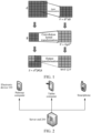
- a specified size 401 of the sliding window is 4 ⁇ 4, and a specified sliding distance 402 includes two elements.
- pixels in the target image input are segmented into several segmented images (such as 401, 403, and 404), and 4 ⁇ 4 pixels are included in each segmented image.
- a blank image may be used to fill the unfilled sliding window. That is, filling may be performed by using pixels of which a pixel value is 0.
- a quantity of input transformations is reduced from H ⁇ W to (H-2)(W-2)/2 ⁇ 2, to reduce the computational volume, and to further improve computing efficiency of the convolutional neural network model.
- step 380 may include the following step.
- the method may include splicing the plurality of output matrices according to the sliding locations of the sliding windows in a case that the sliding windows slide in the target image, and outputting the plurality of output matrices through the output channels of the convolutional layer, to obtain the convolution result.
- the splicing of the convolution result corresponds to the image segmentation performed by the sliding window. That is, for each output matrix, a splicing location of the output matrix in the convolution result may be a sliding location of a sliding window corresponding to the segmented image in a case that the sliding windows slide in the target image.
- the segmented image corresponds to an input matrix corresponding to the output matrix.
- splicing locations of the output matrices in a convolution result output are respectively 405, 406, and 407.
- the image segmentation of the target image and splicing of the convolution result are implemented, and further, learning of local features of the target image by the convolutional layer may be fully implemented.
- step 330 may include the following steps.
- the method may include performing row transformation on the traversed input matrix by using an input parameter matrix, to obtain the first result matrix.
- the method may include obtaining a convolution kernel matrix corresponding to the input matrix, and performing row transformation on the convolution kernel matrix by using a convolution parameter matrix, to obtain the second result matrix.
- g is a convolution kernel matrix corresponding to an input matrix d
- G and G T are known parameter matrices.
- V T B T B T d T
- V T is a first result matrix
- B T is an input parameter matrix
- d is an input matrix
- the original left-multiplying the input matrix d by a known parameter matrix B T and right-multiplying the input matrix d by a known parameter matrix B may be reconstructed into left-multiplying the input matrix d by the input parameter matrix B T twice, thereby further implementing that only elements of which a value is not zero in the input parameter matrix B T participate in the row transformation on the input matrix d.
- the formula (2) may be reconstructed into a formula (6):
- U T G Gg T
- G is a convolution parameter matrix
- g is a convolution kernel matrix
- the original left-multiplying the convolution kernel matrix g by a known parameter matrix G and right-multiplying the convolution kernel matrix g by a known parameter matrix G T may be reconstructed into left-multiplying the convolution kernel matrix g by the convolution parameter matrix G twice, thereby further implementing that only elements of which a value is not zero in the convolution parameter matrix G participate in the row transformation on the convolution kernel matrix g.
- step 370 may include performing row transformation on the to-be-transformed matrix by using an output parameter matrix, to obtain the output matrix.
- an element of which a value is zero may be also included in the known parameter matrix. Even if calculation is performed according to a general matrix multiplication, overheads of computing instructions in the foregoing transformations may be reduced, which is advantageous to improving computing efficiency of the convolutional neural network model.
- the original left-multiplying the to-be-outputted transformation matrix M by a known parameter matrix A T and right-multiplying the to-be-outputted transformation matrix M by a known parameter matrix A may be reconstructed into left-multiplying the to-be-transformed matrix M T by the output parameter matrix A T twice, thereby further implementing that only elements of which a value is not zero in the output parameter matrix A T participate in the row transformation of the to-be-transformed matrix M T .
- the first result matrix V T is a transpose of the input transformation result matrix V
- the second result matrix U T is a transpose of the convolution kernel transformation result matrix U.
- first result matrix and the second result matrix are respectively the transpose of the input transformation result matrix and the transpose of the convolution kernel transformation, before the output transformation is performed, reverse transpose does not need to be performed on the first result matrix and the second result matrix, and the original output result, that is, the output matrix S, is still outputted and obtained.
- the output matrix is obtained by performing row transformation reconstruction on the to-be-transformed matrix M T . Therefore, before the output transformation, reverse transpose does not need to be performed on the first result matrix V T and the second result matrix U T .
- right-multiplying a matrix in the convolutional layer may be transformed into left-multiplying a matrix, thereby further implementing that only elements of which a value is not zero in the known parameter matrices participate in the row transformation reconstruction procedure.
- a reconstruction parameter matrix includes the input parameter matrix, the convolution parameter matrix, or the output parameter matrix.
- a reconstruction input matrix includes the input matrix, the convolution kernel matrix corresponding to the input matrix, or the to-be-transformed matrix.
- a reconstruction output matrix includes the first result matrix, the second result matrix, or the output matrix.
- the row transformation reconstruction procedure that is, performing row transformation on the reconstruction input matrix through the reconstruction parameter matrix, to obtain the reconstruction output matrix, may include the following steps:
- the method may include splicing, for each row in the reconstruction input matrix, elements of the row in the reconstruction input matrix into a row vector corresponding to the row, row vectors corresponding to rows of the reconstruction input matrix constituting a row vector matrix.
- the method may include left-multiplying the reconstruction parameter matrix by the row vector matrix, to obtain an intermediate matrix.
- the method may include transposing the intermediate matrix, and left-multiplying the reconstruction parameter matrix by the transposed intermediate matrix, to obtain the reconstruction output matrix.
- the reconstruction input matrix is X
- the reconstruction parameter matrix is Y
- the reconstruction output matrix is Z
- the intermediate matrix is W
- X x 0 x 1 x 2 x 3 x 4 x 5 x 6 x 7 x 8 x 9 x 10 x 11 x 12 x 13 x 14 x 15
- Y 1 0 ⁇ 1 0 0 1 1 0 0 ⁇ 1 1 0 0 1 0 ⁇ 1 .
- Row vectors vD0, vD1, vD2, and vD3 may correspond to rows that are configured for rows of the reconstruction input matrix X.
- the rows in the reconstruction input matrix X may be stored to the corresponding row vectors, and further constitute the row vector matrix.
- a manner of splicing and storing elements of rows in the reconstruction input matrix X may be performed in descending order as described in this embodiment, or in ascending order, or according to a specified rule. However, the manner is not limited to this embodiment.
- row vector representation of the reconstruction input matrix X may alternatively be understood as that the row vector matrix is a precise representation of a corresponding row in the reconstruction input matrix X. If an element of a row of the reconstruction input matrix is different, a corresponding row vector may be different, and a constituted row vector matrix may also be different.
- the row transformation may be performed on the reconstruction input matrix X based on the row vector matrix.
- the plurality of matrix multiplications that consumes a relatively large quantity of computing instructions is replaced by efficient and compact row transformation instructions, thereby greatly reducing a computational volume, and effectively improving computing efficiency of the convolutional neural network model.
- step 350 may include the following steps.
- the method may include traversing locations of elements in the first result matrix or the second result matrix, and using the traversed location as a current location.
- the method may include obtaining a first element that is located at the current location and that is in the first result matrix and a second element that is located at the current location and that is in the second result matrix.
- step 353 may include the following steps:
- the method may include sequentially traversing the output channels, the sliding windows, and the input channels according to sequences of the output channels, the sliding windows, and the input channels, to determine a current output channel, a current sliding window, and a current input channel that are traversed.
- the method may include determining the first result matrix corresponding to the current input channel and the current sliding window, and the second result matrix corresponding to the current output channel and the current input channel.
- the method may include, respectively extracting elements that are located at the current location and that are in the determined first result matrix and the determined second result matrix, to obtain the first element and the second element.
- the method may include performing a matrix multiplication operation on the obtained first element and the obtained second element, to obtain an element that is located at the current location and that is in the to-be-transformed matrix.
- step 355 may further include the following steps:
- the method may include performing a multiplication operation according to the obtained first element and the obtained second element, to obtain a product result corresponding to the current output channel, the current sliding window, and the current input channel, and iteratively obtain a plurality of product results until all the output channels, all the sliding windows, and all the output channels are traversed.
- the method may include performing an accumulation operation on the plurality of product results, to obtain an accumulation result corresponding to the current location, the accumulation result being used as the element that is located at the current location and that is in the to-be-transformed matrix.
- a volume of multiplication in the matrix multiplication operation is K ⁇ C ⁇ C ⁇ H ⁇ W ⁇ 16.
- the traversal when the traversal is performed for the quantity of the elements, the quantity of the output channels, the quantity of the sliding windows, and the quantity of the input channels, the traversal is sequentially performed according to a sequence of the elements, the output channels, the sliding windows, and the input channels, so that a volume of multiplication in the reconstructed matrix multiplication operation is greatly reduced to 4 ⁇ K ⁇ C ⁇ (H-2) ⁇ (W-2), so that the theoretical speedup of 2.25 of the Winograd F(2 ⁇ 2, 3 ⁇ 3) algorithm can be reached.
- the method may include generating the to-be-transformed matrix from the elements obtained through calculation in a case that locations of all the elements in the first result matrix are traversed.
- step 357 may further include the following steps:
- the method may include obtaining a plurality of accumulation results in a case that the locations of all the elements in the first result matrix are traversed, each accumulation result corresponding to a location of an element.
- the method may include splicing the plurality of accumulation results according to the locations of the corresponding elements, to obtain the to-be-transformed matrix.
- the element M k , c , e T in the to-be-transformed matrix may be calculated and obtained according to the formula (12), and elements in rows constituting the to-be-transformed matrix M T are obtained through element traversal, and further, the to-be-transformed matrix M T is obtained by performing splicing according to element locations.
- the to-be-transformed matrix M T may be obtained by performing splicing according to the locations of the elements until all the elements are calculated.
- the two independent calculation operations that is, the element-wise multiplication and the element-wise addition
- the matrix multiplication may be implemented by using the matrix operation of the level-3 BLAS, which effectively reduces the computational volume, and is more applicable to the electronic device with a Von Neumann architecture.
- the Winograd F(2 ⁇ 2, 3 ⁇ 3) algorithm may reach the theoretical speedup of 2.25 at most, so that computing efficiency of the convolutional neural network model is greatly improved.
- registers may be disposed to store the plurality of product results, and further, the accumulation operation of the plurality of product results may be performed by reading values in the registers, as shown in this embodiment.
- only two registers may be disposed, to reduce consumption of the hardware resources.
- One register may be configured to store a current product result, and another register may be configured to store a previous product result.
- the two product results may be added by reading the values in the registers.
- the values in the two registers may be updated, that is, the current product result is updated to the register storing the previous product result, and the next product result is updated to the register storing the current product result.
- the accumulation operation is performed based on the values in the registers in which the values are updated, to accumulate the plurality of the product results.
- the register are not limited to this embodiment, and may be variously configured according to various hardware resources in different application scenarios.
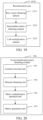
- FIG. 14 is a schematic diagram of a scenario of an image recognition method in an application scenario according to an embodiment.
- the application scenario may include a user 510, a smartphone 530, and a payment server 550.
- a convolutional neural network model may be deployed in the smartphone 530, to provide the user 510 with an intelligent facial recognition service.
- the user 510 performs face swiping through a camera configured in the smartphone 530, so that the smartphone 530 obtains a target image corresponding to the user 510, and facial recognition is further performed on the target image by using the convolutional neural network model deployed in the smartphone 530.
- a plurality of input matrices may be extracted from the target image through input channels of a convolutional layer.
- the plurality of input matrices may be traversed, and input transformation and convolution kernel transformation may be performed on the traversed input matrices, to respectively obtain first result matrices and second result matrices.
- a matrix multiplication reconstruction may be further performed on the first result matrices and the second result matrices, to obtain to-be-transformed matrices, and then output transformation may be performed on the to-be-transformed matrices through row transformation reconstruction, to obtain a plurality of output matrices.
- a convolution result obtained by splicing the plurality of output matrices may be inputted into a pooling layer in the convolutional neural network model, for subsequent facial recognition on the target image, thereby obtaining a facial recognition result.
- the smartphone 530 may initiate an order payment request to the payment server 550 for the to-be-paid order, to finish a payment process of the to-be-paid order.
- the row transformation reconstruction and matrix multiplication reconstruction method provided according to embodiments of the disclosure is 8.67 to 35.4 times faster than other conventional algorithms.
- Table 1 below shows image recognition performance of embodiments of the disclosure for smartphones of different models (A1 to A4) under different quantities (1 to 4) of threads.
- the image recognition method according to the embodiments has better compatibility, and peak value performance may reach performing image recognition within 357.75 ms.
- an apparatus may be configured to implement the image recognition method described above. Accordingly, some details may be omitted as they are provided in the descriptions above.
- an image recognition apparatus 900 may include an input matrix extraction module 910, a result matrix obtaining module 930, a to-be-transformed matrix obtaining module 950, an output matrix obtaining module 970, a convolution result obtaining module 980, and an image recognition module 990.
- the to-be-transformed matrix obtaining module 950 may be configured to perform matrix multiplication reconstruction on the first result matrices and the second result matrices, to obtain to-be-transformed matrices.
- the output matrix obtaining module 970 may be configured to perform output transformation on the to-be-transformed matrices through row transformation reconstruction, to obtain a plurality of output matrices.
- the convolution result obtaining module 980 may be configured to splice the plurality of output matrices after all the input matrices are traversed, and output the plurality of output matrices through output channels of the convolutional layer, to obtain a convolution result, each output matrix corresponding to each input matrix.
- the image recognition module 990 may be configured to input the convolution result into a pooling layer in the convolutional neural network model, and perform image recognition on the target image, to obtain an image recognition result.
- the input matrix extraction module 910 may include a sliding control unit 911 and an output unit 913.
- the sliding control unit 911 may be configured to control sliding windows to slide in the target image, and perform image segmentation on the target image, to obtain a plurality of segmented images, each segmented image corresponding to a sliding location of the sliding window in a case that the sliding windows slide in the target image.
- the output unit 913 may be configured to output the plurality of segmented images through the input channels of the convolutional layer, to obtain the plurality of input matrices, each input matrix corresponding to one segmented image, and a size of each input matrix being equal to a specified size of the sliding window.
- the convolution result obtaining module 980 may include a sliding splicing unit.
- the sliding splicing unit may be configured to splice the plurality of output matrices according to the sliding locations of the sliding windows in a case that the sliding windows slide in the target image, and output the plurality of output matrices through the output channels of the convolutional layer, to obtain the convolution result.
- the result matrix obtaining module 930 may include a first reconstruction unit 931 and a second reconstruction unit 933.
- the first reconstruction unit 931 may be configured to perform row transformation on the traversed input matrix by using an input parameter matrix, to obtain the first result matrix.
- the second reconstruction unit 933 may be configured to obtain a convolution kernel matrix corresponding to the input matrix, and perform row transformation on the convolution kernel matrix by using a convolution parameter matrix, to obtain the second result matrix.
- the output matrix obtaining module 970 may include a third reconstruction unit 971.
- the third reconstruction unit 971 may be configured to perform row transformation on the to-be-transformed matrix by using an output parameter matrix, to obtain the output matrix.
- the reconstruction parameter matrix may include the input parameter matrix, the convolution parameter matrix, or the output parameter matrix.
- a reconstruction input matrix includes the input matrix, the convolution kernel matrix corresponding to the input matrix, or the to-be-transformed matrix.
- a reconstruction output matrix includes the first result matrix, the second result matrix, or the output matrix.
- a reconstruction unit 1010 may include a row vector obtaining subunit 1011, an intermediate matrix obtaining subunit 1013, and a left-multiplication subunit 1015.
- the row vector obtaining subunit 1011 may be configured to splice, for each row in the reconstruction input matrix, elements of the row in the reconstruction input matrix into a row vector corresponding to the row, row vectors corresponding to rows of the reconstruction input matrix constituting a row vector matrix.
- the left-multiplication subunit 1015 may be configured to transpose the intermediate matrix, and left-multiply the reconstruction parameter matrix by the transposed intermediate matrix, to obtain the reconstruction output matrix.
- the to-be-transformed matrix obtaining module 950 may include a location traversal unit 951, an element obtaining unit 953, a matrix multiplication operation unit 955, and a matrix generation unit 957.
- the location traversal unit 951 may be configured to traverse locations of elements in the first result matrix, and use the traversed location as a current location.
- the element obtaining unit 953 may be configured to obtain a first element that is located at the current location and that is in the first result matrix and a second element that is located at the current location and that is in the second result matrix.
- the matrix multiplication operation unit 955 may be configured to perform a matrix multiplication operation on the obtained first element and the obtained second element, to obtain an element that is located at the current location and that is in the to-be-transformed matrix.
- the matrix generation unit 957 may be configured to generate the to-be-transformed matrix through the elements obtained through calculation in a case that locations of all the elements in the first result matrix are traversed.
- the element obtaining unit 953 may include a traversal subunit, a matrix determining subunit, and an element extraction subunit.
- the traversal subunit may be configured to sequentially traverse the output channels, the sliding windows, and the input channels according to sequences of the output channels, the sliding windows, and the input channels, to determine a current output channel, a current sliding window, and a current input channel that are traversed.
- the matrix determining subunit may be configured to determine the first result matrix corresponding to the current input channel and the current sliding window, and the second result matrix corresponding to the current output channel and the current input channel.
- the element extraction subunit may be configured to respectively extract elements that are located at the current location and that are in the determined first result matrix and the determined second result matrix, to obtain the first element and the second element.
- the matrix multiplication operation unit 955 may include a multiplication operation subunit and an accumulation operation subunit.
- the multiplication operation subunit may be configured to perform a multiplication operation according to the obtained first element and the obtained second element, to obtain a product result corresponding to the current output channel, the current sliding window, and the current input channel, and obtain a plurality of product results until all the output channels, all the sliding windows, and all the output channels are traversed.
- the accumulation operation subunit may be configured to perform an accumulation operation on the plurality of product results, to obtain an accumulation result corresponding to the current location, the accumulation result being used as the element that is located at the current location and that is in the to-be-transformed matrix.
- the matrix generation unit 957 may include an accumulation result obtaining subunit and an accumulation result splicing subunit.
- the accumulation result obtaining subunit may be configured to obtain a plurality of accumulation results in a case that the locations of all the elements in the first result matrix are traversed, each accumulation result corresponding to a location of an element.
- the accumulation result splicing subunit may be configured to splice the plurality of accumulation results according to the locations of the corresponding elements, to obtain the to-be-transformed matrix.
- the image recognition module 990 may include a feature compression unit, a feature splicing unit, and a result output unit.
- the feature compression unit may be configured to perform feature compression on the convolution result through the pooling layer in the convolutional neural network model.
- the feature splicing unit may be configured to perform connection for a compressed feature through a fully-connected layer, and input the compressed feature into a loss layer.
- the result output unit may be configured to calculate a loss value of the loss layer based on the input of the fully-connected layer, and output, through the loss layer, the image recognition result in a case that the loss value of the loss layer is minimum.
- the image recognition apparatus performs image recognition processing
- the image recognition apparatus is divided into various functional modules, this is only an example.
- the functions may be combined or modified according to different functional implementations, that is, an internal structure of the image recognition apparatus may be modified into different functional modules, so as to perform all or some of the functions described above.
- the memory 1002 stores a computer-readable instruction, the computer-readable instruction, when executed by the processor 1001, performs the image recognition method in the foregoing embodiments.
- a storage medium storing a computer program may be provided.
- the computer program when executed by a processor, may perform the image recognition method in the foregoing embodiments.
Landscapes
- Engineering & Computer Science (AREA)
- Theoretical Computer Science (AREA)
- Physics & Mathematics (AREA)
- General Physics & Mathematics (AREA)
- Data Mining & Analysis (AREA)
- Evolutionary Computation (AREA)
- Mathematical Physics (AREA)
- Computing Systems (AREA)
- Software Systems (AREA)
- Artificial Intelligence (AREA)
- General Engineering & Computer Science (AREA)
- General Health & Medical Sciences (AREA)
- Health & Medical Sciences (AREA)
- Life Sciences & Earth Sciences (AREA)
- Biomedical Technology (AREA)
- Molecular Biology (AREA)
- Computational Linguistics (AREA)
- Biophysics (AREA)
- Databases & Information Systems (AREA)
- Computer Vision & Pattern Recognition (AREA)
- Mathematical Analysis (AREA)
- Computational Mathematics (AREA)
- Pure & Applied Mathematics (AREA)
- Mathematical Optimization (AREA)
- Medical Informatics (AREA)
- Multimedia (AREA)
- Algebra (AREA)
- Bioinformatics & Cheminformatics (AREA)
- Evolutionary Biology (AREA)
- Bioinformatics & Computational Biology (AREA)
- Image Analysis (AREA)
Claims (15)
- Bilderkennungsverfahren, durchgeführt von einer elektronischen Vorrichtung, das Verfahren umfassend:Extrahieren (310) einer Vielzahl von Eingangsmatrizen aus einem Zielbild durch Eingangskanäle einer Faltungsschicht in einem faltenden neuronalen Netzmodell, wobei das faltende neuronale Netzmodell in der elektronischen Vorrichtung ausgeführt wird;Erlangen (330) von ersten Resultatmatrizen durch Durchlaufen der Vielzahl von Eingangsmatrizen und Durchführen von Eingangstransformation an der durchlaufenen Vielzahl von Eingangsmatrizen durch Zeilentransformation-Rekonstruktion;Erlangen (330) von zweiten Resultatmatrizen durch Durchführen von Faltungskernel-Transformation an der durchlaufenen Vielzahl von Eingangsmatrizen durch die Zeilentransformation-Rekonstruktion, umfassend: Erlangen der zweiten Resultatmatrizen durch Durchführen der Faltungskernel-Transformation an Faltungskernel-Matrizen, die der durchlaufenen Vielzahl von Eingangsmatrizen entsprechen; und wobei die Faltungskernel-Matrizen während eines Modelltrainings des faltenden neuronalen Netzmodells erzeugt wird, wobei die Faltungskernel-Matrizen unter Verwendung von Trainingsproben für die Eingangsmatrizen trainiert werden;Durchführen (350) von Matrizenmultiplikation-Rekonstruktion an den ersten Resultatmatrizen und den zweiten Resultatmatrizen, um zu transformierende Matrizen zu erlangen;Durchführen (370) von Ausgangstransformation an den zu transformierenden Matrizen durch die Zeilentransformation-Rekonstruktion, um eine Vielzahl von Ausgangsmatrizen zu erlangen;basierend auf einem Durchlaufen aller der Vielzahl von Eingangsmatrizen, Spleißen (380) der Vielzahl von Ausgangsmatrizen und Ausgeben (380) der gespleißten Vielzahl von Ausgangsmatrizen durch Ausgangskanäle der Faltungsschicht, um ein Faltungsresultat zu erlangen, wobei jede gespleißte Ausgangsmatrize der Vielzahl von gespleißten Ausgangsmatrizen jeder Eingangsmatrize der Vielzahl von Eingangsmatrizen entspricht; undErlangen (390) eines Bilderkennungsresultats durch Eingeben des Faltungsresultats in eine Pooling-Schicht in dem faltenden neuronalen Netzmodell, um eine Bilderkennung an dem Zielbild durchzuführen.
- Verfahren nach Anspruch 1, wobei das Extrahieren (310) der Vielzahl von Eingangsmatrizen aus dem Zielbild durch die Eingangskanäle der Faltungsschicht Folgendes umfasst:Steuern (311) von Gleitfenstern, um in dem Zielbild zu gleiten, und Durchführen (311) einer Bildsegmentierung an dem Zielbild, um eine Vielzahl von segmentierten Bildern zu erlangen, wobei jedes segmentierte Bild einer Gleitstelle des Gleitfensters in einem Fall entspricht, dass die Gleitfenster in dem Zielbild gleiten; undAusgeben (313) der Vielzahl von segmentierten Bildern durch die Eingangskanäle der Faltungsschicht, um die Vielzahl von Eingangsmatrizen zu erlangen, wobei jede Eingangsmatrize jedem der Vielzahl von segmentierten Bildern entspricht und eine Größe jeder Eingangsmatrize gleich wie eine spezifizierte Größe des Gleitfensters ist.
- Verfahren nach Anspruch 2, wobei das Spleißen (380) der Vielzahl von Ausgangsmatrizen und Ausgeben (380) der Vielzahl von Ausgangsmatrizen durch die Ausgangskanäle der Faltungsschicht ferner Folgendes umfasst:
Spleißen der Vielzahl von Ausgangsmatrizen gemäß den Gleitpositionen der Gleitfenster in einem Fall, in dem die Gleitfenster in dem Zielbild gleiten, und Ausgeben der Vielzahl von Ausgangsmatrizen über die Ausgangskanäle der Faltungsschicht, um das Faltungsresultat zu erlangen. - Verfahren nach einem der Ansprüche 1 bis 3, wobei das Durchlaufen (330) der Vielzahl von Eingangsmatrizen, das Durchführen (330) einer Eingangstransformation an den durchlaufenen Eingangsmatrizen durch Zeilentransformation-Rekonstruktion, um erste Resultatmatrizen zu erlangen, und das Durchführen (330) einer Faltungskernel-Transformation an den durchlaufenen Eingangsmatrizen durch Zeilentransformation-Rekonstruktion, um zweite Resultatmatrizen zu erlangen, Folgendes umfasst:Durchführen (331) einer Zeilentransformation an der durchlaufenen Vielzahl von Eingangsmatrizen basierend auf einer Eingabeparametermatrize; undErlangen (333) einer Faltungskernel-Matrize, die der Eingangsmatrize entspricht, und Durchführen (333) von Zeilentransformation an der Faltungskernel-Matrize basierend auf einer Faltungsparameter-Matrize.
- Verfahren nach einem der Ansprüche 1 bis 4, wobei das Durchführen (370) der Ausgangstransformation an den zu transformierenden Matrizen durch Zeilentransformation-Rekonstruktion ferner Folgendes umfasst:
Durchführen von Zeilentransformation an der zu transformierenden Matrize basierend auf einer Ausgangsparametermatrize. - Verfahren nach Anspruch 4 oder 5, wobei eine Rekonstruktionsparametermatrize mindestens eine von der Eingangsparametermatrize, der Faltungsparametermatrize oder der Ausgangsparametermatrize umfasst,wobei eine Rekonstruktionseingangsmatrize mindestens eine von der Eingangsmatrize, wobei die Faltungskernel-Matrize der Eingangsmatrize entspricht, oder der zu transformierenden Matrize umfasst;wobei eine Rekonstruktionsausgangsmatrize mindestens eine von der ersten Resultatmatrize, der zweiten Resultatmatrize oder der Ausgangsmatrize umfasst, undwobei das Verfahren ferner Folgendes umfasst: Durchführen von Zeilentransformation an der Rekonstruktionseingangsmatrize durch die Rekonstruktionsparametermatrize, um die Rekonstruktionsausgangsmatrize zu erlangen;Spleißen (511), für jede Zeile in der Rekonstruktionseingangsmatrize, von Elementen der Zeile in der Rekonstruktionseingangsmatrize in einen Zeilenvektor, der der Zeile entspricht, wobei die Zeilenvektoren, die den Zeilen der Rekonstruktionseingangsmatrize entsprechen, eine Zeilenvektormatrize bilden;Linksmultiplizieren (513) der Rekonstruktionsparametermatrize mit der Zeilenvektormatrize, um eine Zwischenmatrize zu erlangen; undTransponieren (515) der Zwischenmatrize, und Linksmultiplizieren (515) der Rekonstruktionsparametermatrize mit der transponierten Zwischenmatrize, um die Rekonstruktionsausgangsmatrize zu erlangen.
- Verfahren nach einem der Ansprüche 1 bis 6, wobei das Durchführen von Matrizenmultiplikationsrekonstruktion an den ersten Resultatmatrizen und den zweiten Resultatmatrizen Folgendes umfasst:
Durchlaufen (351) von Positionen von Elementen in der ersten Resultatmatrize und Verwenden (351) der durchlaufenen Position als aktuelle Position;Erlangen (353) eines ersten Elements, das sich an der aktuellen Position befindet und in der ersten Resultatmatrize ist, und Erlangen (353) eines zweiten Elements, das sich an der aktuellen Position in der zweiten Resultatmatrize befindet;Durchführen (355) einer Matrizenmultiplikationsoperation an dem erlangten ersten Element und dem erlangten zweiten Element, um ein Element zu erlangen, das sich an der aktuellen Position befindet und das in der zu transformierenden Matrize ist; undErzeugen (357) der zu transformierenden Matrize aus den Elementen, die durch Berechnung basierend auf den Positionen aller Elemente in der ersten durchlaufenen Resultatmatrize erlangt werden. - Verfahren nach Anspruch 7, wobei das Erlangen des ersten Elements, das sich an der aktuellen Position in der ersten Resultatmatrize befindet, und des zweiten Elements, das sich an der aktuellen Position in der zweiten Resultatmatrize befindet, Folgendes umfasst:sequentielles (3531) Durchlaufen der Ausgangskanäle, der Gleitfenster und der Eingangskanäle gemäß einer Sequenz der Ausgangskanäle, der Gleitfenster und der Eingangskanäle, um einen aktuellen Ausgangskanal, ein aktuelles Gleitfenster und einen aktuellen Eingangskanal zu bestimmen, die durchlaufen werden;Bestimmen (3533) der ersten Resultatmatrize, die dem aktuellen Eingangskanal und dem aktuellen Gleitfenster entspricht, und der zweiten Resultatmatrize, die dem aktuellen Ausgangskanal und dem aktuellen Eingangskanal entspricht; undjeweiliges Extrahieren (3535) von Elementen, die sich an der aktuellen Position befinden und die in der bestimmten ersten Resultatmatrize und der bestimmten zweiten Resultatmatrize sind, um das erste Element und das zweite Element zu erlangen.
- Verfahren nach Anspruch 8, wobei das Durchführen der Matrizenmultiplikationsoperation an dem erlangten ersten Element und dem erlangten zweiten Element, um das Element zu erlangen, das sich an der aktuellen Position befindet und das in der zu transformierenden Matrize ist, Folgendes umfasst:Durchführen (3551) der Multiplikationsoperation gemäß dem erlangten ersten Element und dem erlangten zweiten Element, um ein Produktergebnis zu erlangen, das dem aktuellen Ausgangskanal, dem aktuellen Gleitfenster und dem aktuellen Eingangskanal entspricht, und Erlangen (3551) einer Vielzahl von Produktresultaten basierend auf allen Ausgangskanäle, allen Gleitfenster und allen durchlaufenen Ausgangskanälen; undDurchführen (3553) einer Akkumulationsoperation an der Vielzahl von Produktresultaten, um ein Akkumulationsresultat zu erlangen, das der aktuellen Position entspricht, wobei das Akkumulationsresultat als das Element verwendet wird, das sich an der aktuellen Position befindet und das in der zu transformierenden Matrize ist.
- Verfahren nach Anspruch 9, wobei das Erzeugen der zu transformierenden Matrize aus den Elementen, die durch Berechnung basierend auf der Positionen aller Elemente in der ersten Resultatmatrize, die durchlaufen wird, erlangt werden, Folgendes umfasst:Erlangen (3571) einer Vielzahl von Akkumulationsresultaten basierend auf den Positionen aller Elemente in der ersten Resultatmatrize, die durchlaufen wird, wobei jedes Akkumulationsresultat einer Position eines Elements entspricht; undSpleißen (3573) der Vielzahl von Akkumulationsresultaten gemäß den Positionen der entsprechenden Elemente, um die zu transformierende Matrize zu erlangen.
- Verfahren nach einem der Ansprüche 1 bis 10, wobei das Erlangen des Bilderkennungsresultats durch Eingeben des Faltungsresultats in die Pooling-Schicht in dem faltenden neuronalen Netzmodell und das Durchführen der Bilderkennung an dem Zielbild Folgendes umfasst:Durchführen (391) von Merkmalskompression an dem Faltungsresultat durch die Pooling-Schicht in dem faltenden neuronalen Netzmodell;Verbinden (393) eines komprimierten Merkmals durch eine vollständig verbundene Schicht, und Eingeben des komprimierten Merkmals in eine Verlustschicht; undBerechnen (395) eines Verlustwerts der Verlustschicht basierend auf der Eingabe der vollständig verbundenen Schicht, und Ausgeben (395) des Bilderkennungsresultats durch die Verlustschicht basierend darauf, dass der Verlustwert der Verlustschicht ein Minimalwert ist.
- Bilderkennungsgerät, umfassend Einrichtungen, die zum Durchführen des Bilderkennungsverfahrens nach einem der Ansprüche 1 bis 11 konfiguriert sind
- Computerprogramm, umfassend Anweisungen, die, wenn das Programm von einem Prozessor ausgeführt wird, den Computer veranlassen, das Bilderkennungsverfahren nach einem der Ansprüche 1 bis 11 durchzuführen.
- Speichermedium, das ein Computerprogramm speichert, wobei das Computerprogramm, wenn es von einem Prozessor ausgeführt wird, das Bilderkennungsverfahren nach einem der Ansprüche 1 bis 11 implementiert.
- Elektronische Vorrichtung, zum Beispiel ein Tablet-Computer, ein Palmtop-Computer, ein Smartphone, ein unbemanntes Luftfahrzeug, ein Roboter, eine tragbare intelligente Vorrichtung, wie beispielsweise eine intelligente Brille oder eine intelligente Kamera, umfassend eine Bilderkennungsvorrichtung nach Anspruch 12.
Applications Claiming Priority (2)
| Application Number | Priority Date | Filing Date | Title |
|---|---|---|---|
| CN201810310628.XA CN110263909B (zh) | 2018-03-30 | 2018-03-30 | 图像识别方法及装置 |
| PCT/CN2019/076816 WO2019184657A1 (zh) | 2018-03-30 | 2019-03-04 | 图像识别方法、装置、电子设备及存储介质 |
Publications (3)
| Publication Number | Publication Date |
|---|---|
| EP3779800A1 EP3779800A1 (de) | 2021-02-17 |
| EP3779800A4 EP3779800A4 (de) | 2021-07-14 |
| EP3779800B1 true EP3779800B1 (de) | 2025-05-07 |
Family
ID=67911874
Family Applications (1)
| Application Number | Title | Priority Date | Filing Date |
|---|---|---|---|
| EP19778369.9A Active EP3779800B1 (de) | 2018-03-30 | 2019-03-04 | Bilderkennungsverfahren, vorrichtung, elektronische vorrichtung und speichermedium |
Country Status (4)
| Country | Link |
|---|---|
| US (1) | US11609968B2 (de) |
| EP (1) | EP3779800B1 (de) |
| CN (1) | CN110263909B (de) |
| WO (1) | WO2019184657A1 (de) |
Families Citing this family (21)
| Publication number | Priority date | Publication date | Assignee | Title |
|---|---|---|---|---|
| KR102228586B1 (ko) * | 2018-01-19 | 2021-03-16 | 한국전자통신연구원 | Gpu 기반의 적응적 blas 연산 가속화 장치 및 방법 |
| CN112825151B (zh) * | 2019-11-20 | 2024-09-13 | 上海商汤智能科技有限公司 | 数据处理方法、装置及设备 |
| US11507831B2 (en) | 2020-02-24 | 2022-11-22 | Stmicroelectronics International N.V. | Pooling unit for deep learning acceleration |
| CN111368941B (zh) * | 2020-04-10 | 2023-09-01 | 浙江大华技术股份有限公司 | 一种图像处理方法、装置以及计算机存储介质 |
| CN113537447A (zh) * | 2020-04-20 | 2021-10-22 | 佳能株式会社 | 多层神经网络的生成方法、装置、应用方法及存储介质 |
| WO2021253440A1 (en) * | 2020-06-19 | 2021-12-23 | Alibaba Group Holding Limited | Depth-wise over-parameterization |
| CN112508849A (zh) * | 2020-11-09 | 2021-03-16 | 中国科学院信息工程研究所 | 数字图像拼接检测方法及装置 |
| CN112651451B (zh) * | 2020-12-30 | 2023-08-11 | 北京百度网讯科技有限公司 | 图像识别方法、装置、电子设备及存储介质 |
| CN112749576B (zh) * | 2021-03-09 | 2022-02-01 | 腾讯科技(深圳)有限公司 | 图像识别方法和装置、计算设备以及计算机存储介质 |
| CN112991142B (zh) | 2021-03-31 | 2023-06-16 | 腾讯科技(深圳)有限公司 | 图像数据的矩阵运算方法、装置、设备及存储介质 |
| CN113570031B (zh) * | 2021-06-08 | 2024-02-02 | 中国科学院深圳先进技术研究院 | 卷积运算的处理方法、电子设备及计算机可读存储介质 |
| CN113283591B (zh) * | 2021-07-22 | 2021-11-16 | 南京大学 | 基于Winograd算法和近似乘法器的高效卷积实现方法及装置 |
| US20230068168A1 (en) * | 2021-08-18 | 2023-03-02 | Micron Technology, Inc. | Neural network transpose layer removal |
| CN113742188A (zh) * | 2021-08-25 | 2021-12-03 | 宁波大学 | 一种基于bert的非侵入式电脑行为监测方法及系统 |
| CN113793264B (zh) * | 2021-09-07 | 2022-11-15 | 北京航星永志科技有限公司 | 一种基于卷积模型的档案图像处理方法、系统和电子设备 |
| CN113868592B (zh) * | 2021-09-13 | 2025-06-03 | 珠海亿智电子科技有限公司 | 基于g2d实现卷积计算的方法及系统 |
| CN116152140B (zh) * | 2021-11-20 | 2025-12-23 | 清华大学 | 基于忆阻器阵列的图像识别方法、装置和计算机设备 |
| CN114078225B (zh) * | 2021-11-23 | 2025-04-29 | 华润数字科技有限公司 | 基于塔克分解的回转窑状态识别方法及其相关设备 |
| CN114611667B (zh) * | 2022-03-09 | 2023-05-26 | 贵州大学 | 一种基于小规模参数矩阵计算特征图边界的重构方法 |
| CN118573784B (zh) * | 2024-07-31 | 2024-09-27 | 湖南紫先数字科技有限公司 | Winograd算法中机密机制的嵌入方法及系统 |
| CN120148257B (zh) * | 2025-03-14 | 2025-12-09 | 长沙理工大学 | 一种基于感知通信一体化设备的成像方法及系统 |
Citations (1)
| Publication number | Priority date | Publication date | Assignee | Title |
|---|---|---|---|---|
| US20150146915A1 (en) * | 2012-12-18 | 2015-05-28 | Intel Corporation | Hardware convolution pre-filter to accelerate object detection |
Family Cites Families (9)
| Publication number | Priority date | Publication date | Assignee | Title |
|---|---|---|---|---|
| US20170344876A1 (en) * | 2016-05-31 | 2017-11-30 | Samsung Electronics Co., Ltd. | Efficient sparse parallel winograd-based convolution scheme |
| WO2017214968A1 (en) * | 2016-06-17 | 2017-12-21 | Nokia Technologies Oy | Method and apparatus for convolutional neural networks |
| CN106326985A (zh) * | 2016-08-18 | 2017-01-11 | 北京旷视科技有限公司 | 神经网络训练方法和装置及数据处理方法和装置 |
| CN106709441B (zh) * | 2016-12-16 | 2019-01-29 | 北京工业大学 | 一种基于卷积定理的人脸验证加速方法 |
| CN107247949B (zh) * | 2017-08-02 | 2020-06-19 | 智慧眼科技股份有限公司 | 基于深度学习的人脸识别方法、装置和电子设备 |
| CN107480788A (zh) * | 2017-08-11 | 2017-12-15 | 广东工业大学 | 一种深度卷积对抗生成网络的训练方法及训练系统 |
| CN107545279B (zh) * | 2017-08-30 | 2020-07-31 | 电子科技大学 | 基于卷积神经网络与加权核特征分析的图像识别方法 |
| CN107609638B (zh) * | 2017-10-12 | 2019-12-10 | 湖北工业大学 | 一种基于线性编码器和插值采样优化卷积神经网络的方法 |
| CN107704921A (zh) * | 2017-10-19 | 2018-02-16 | 北京智芯原动科技有限公司 | 基于Neon指令的卷积神经网络的算法优化方法及装置 |
-
2018
- 2018-03-30 CN CN201810310628.XA patent/CN110263909B/zh active Active
-
2019
- 2019-03-04 EP EP19778369.9A patent/EP3779800B1/de active Active
- 2019-03-04 WO PCT/CN2019/076816 patent/WO2019184657A1/zh not_active Ceased
-
2020
- 2020-06-18 US US16/905,010 patent/US11609968B2/en active Active
Patent Citations (1)
| Publication number | Priority date | Publication date | Assignee | Title |
|---|---|---|---|---|
| US20150146915A1 (en) * | 2012-12-18 | 2015-05-28 | Intel Corporation | Hardware convolution pre-filter to accelerate object detection |
Also Published As
| Publication number | Publication date |
|---|---|
| CN110263909A (zh) | 2019-09-20 |
| EP3779800A1 (de) | 2021-02-17 |
| US11609968B2 (en) | 2023-03-21 |
| CN110263909B (zh) | 2022-10-28 |
| US20200320369A1 (en) | 2020-10-08 |
| EP3779800A4 (de) | 2021-07-14 |
| WO2019184657A1 (zh) | 2019-10-03 |
Similar Documents
| Publication | Publication Date | Title |
|---|---|---|
| US11609968B2 (en) | Image recognition method, apparatus, electronic device and storage medium | |
| CN111368685B (zh) | 关键点的识别方法、装置、可读介质和电子设备 | |
| EP3982588A1 (de) | Homomorpher operationsbeschleuniger und vorrichtung zur durchführung homomorpher operationen damit | |
| CN113609495A (zh) | 用于同态加密处理的设备和方法、包括该设备的系统 | |
| CN111402130A (zh) | 数据处理方法和数据处理装置 | |
| CN114913061A (zh) | 一种图像处理方法、装置、存储介质及电子设备 | |
| WO2022165675A1 (zh) | 一种手势识别方法、装置、终端设备及可读存储介质 | |
| CN110378203B (zh) | 图像处理方法、装置、终端及存储介质 | |
| WO2022001364A1 (zh) | 一种提取数据特征的方法和相关装置 | |
| CN111428568B (zh) | 活体视频图片处理方法、装置、计算机设备和存储介质 | |
| CN114254563A (zh) | 数据处理方法及装置、电子设备、存储介质 | |
| CN114387197B (zh) | 一种双目图像处理方法、装置、设备和存储介质 | |
| US20240171727A1 (en) | Cross-view attention for visual perception tasks using multiple camera inputs | |
| EP3971781A1 (de) | Verfahren und vorrichtung mit operation von neuronalem netz | |
| US12524896B2 (en) | Method and apparatus for estimating depth of image | |
| CN116524532B (zh) | 动作识别方法、装置、存储介质以及电子设备 | |
| CN114726506B (zh) | 数据加密方法、装置、计算机设备及存储介质 | |
| CN119180333A (zh) | 用于视觉数据处理的方法、装置、设备和存储介质 | |
| CN119251784A (zh) | 一种基于时序鸟瞰图的车道线识别方法、装置、非暂时性计算机可读存储介质及车辆 | |
| JP2025529792A (ja) | 顔認識方法及び装置 | |
| CN113538205A (zh) | 基于surf算法的特征点检测方法和装置 | |
| CN115861901B (zh) | 视频分类方法、装置、设备及存储介质 | |
| CN115526926B (zh) | 目标深度估计模型训练方法和目标深度估计方法 | |
| CN114283060B (zh) | 视频生成方法、装置、设备及存储介质 | |
| CN117333790B (zh) | 视频事件的相似性判断方法、装置和电子设备 |
Legal Events
| Date | Code | Title | Description |
|---|---|---|---|
| STAA | Information on the status of an ep patent application or granted ep patent |
Free format text: STATUS: THE INTERNATIONAL PUBLICATION HAS BEEN MADE |
|
| PUAI | Public reference made under article 153(3) epc to a published international application that has entered the european phase |
Free format text: ORIGINAL CODE: 0009012 |
|
| STAA | Information on the status of an ep patent application or granted ep patent |
Free format text: STATUS: REQUEST FOR EXAMINATION WAS MADE |
|
| 17P | Request for examination filed |
Effective date: 20200827 |
|
| AK | Designated contracting states |
Kind code of ref document: A1 Designated state(s): AL AT BE BG CH CY CZ DE DK EE ES FI FR GB GR HR HU IE IS IT LI LT LU LV MC MK MT NL NO PL PT RO RS SE SI SK SM TR |
|
| AX | Request for extension of the european patent |
Extension state: BA ME |
|
| DAV | Request for validation of the european patent (deleted) | ||
| DAX | Request for extension of the european patent (deleted) | ||
| A4 | Supplementary search report drawn up and despatched |
Effective date: 20210611 |
|
| RIC1 | Information provided on ipc code assigned before grant |
Ipc: G06N 3/04 20060101AFI20210607BHEP Ipc: G06F 17/16 20060101ALI20210607BHEP Ipc: G06N 3/08 20060101ALI20210607BHEP Ipc: G06K 9/62 20060101ALI20210607BHEP |
|
| RAP3 | Party data changed (applicant data changed or rights of an application transferred) |
Owner name: TENCENT TECHNOLOGY (SHENZHEN) COMPANY LIMITED |
|
| STAA | Information on the status of an ep patent application or granted ep patent |
Free format text: STATUS: EXAMINATION IS IN PROGRESS |
|
| 17Q | First examination report despatched |
Effective date: 20240604 |
|
| GRAP | Despatch of communication of intention to grant a patent |
Free format text: ORIGINAL CODE: EPIDOSNIGR1 |
|
| STAA | Information on the status of an ep patent application or granted ep patent |
Free format text: STATUS: GRANT OF PATENT IS INTENDED |
|
| RIC1 | Information provided on ipc code assigned before grant |
Ipc: G06V 10/82 20220101ALI20240923BHEP Ipc: G06V 10/70 20220101ALI20240923BHEP Ipc: G06N 3/045 20230101ALI20240923BHEP Ipc: G06F 18/21 20230101ALI20240923BHEP Ipc: G06N 3/08 20060101ALI20240923BHEP Ipc: G06F 17/16 20060101ALI20240923BHEP Ipc: G06N 3/04 20060101AFI20240923BHEP |
|
| INTG | Intention to grant announced |
Effective date: 20241004 |
|
| GRAS | Grant fee paid |
Free format text: ORIGINAL CODE: EPIDOSNIGR3 |
|
| GRAA | (expected) grant |
Free format text: ORIGINAL CODE: 0009210 |
|
| STAA | Information on the status of an ep patent application or granted ep patent |
Free format text: STATUS: THE PATENT HAS BEEN GRANTED |
|
| AK | Designated contracting states |
Kind code of ref document: B1 Designated state(s): AL AT BE BG CH CY CZ DE DK EE ES FI FR GB GR HR HU IE IS IT LI LT LU LV MC MK MT NL NO PL PT RO RS SE SI SK SM TR |
|
| REG | Reference to a national code |
Ref country code: GB Ref legal event code: FG4D |
|
| REG | Reference to a national code |
Ref country code: CH Ref legal event code: EP |
|
| REG | Reference to a national code |
Ref country code: DE Ref legal event code: R096 Ref document number: 602019069680 Country of ref document: DE |
|
| REG | Reference to a national code |
Ref country code: IE Ref legal event code: FG4D |
|
| REG | Reference to a national code |
Ref country code: NL Ref legal event code: MP Effective date: 20250507 |
|
| PG25 | Lapsed in a contracting state [announced via postgrant information from national office to epo] |
Ref country code: FI Free format text: LAPSE BECAUSE OF FAILURE TO SUBMIT A TRANSLATION OF THE DESCRIPTION OR TO PAY THE FEE WITHIN THE PRESCRIBED TIME-LIMIT Effective date: 20250507 Ref country code: ES Free format text: LAPSE BECAUSE OF FAILURE TO SUBMIT A TRANSLATION OF THE DESCRIPTION OR TO PAY THE FEE WITHIN THE PRESCRIBED TIME-LIMIT Effective date: 20250507 Ref country code: PT Free format text: LAPSE BECAUSE OF FAILURE TO SUBMIT A TRANSLATION OF THE DESCRIPTION OR TO PAY THE FEE WITHIN THE PRESCRIBED TIME-LIMIT Effective date: 20250908 |
|
| REG | Reference to a national code |
Ref country code: LT Ref legal event code: MG9D |
|
| PG25 | Lapsed in a contracting state [announced via postgrant information from national office to epo] |
Ref country code: GR Free format text: LAPSE BECAUSE OF FAILURE TO SUBMIT A TRANSLATION OF THE DESCRIPTION OR TO PAY THE FEE WITHIN THE PRESCRIBED TIME-LIMIT Effective date: 20250808 Ref country code: NO Free format text: LAPSE BECAUSE OF FAILURE TO SUBMIT A TRANSLATION OF THE DESCRIPTION OR TO PAY THE FEE WITHIN THE PRESCRIBED TIME-LIMIT Effective date: 20250807 |
|
| PG25 | Lapsed in a contracting state [announced via postgrant information from national office to epo] |
Ref country code: PL Free format text: LAPSE BECAUSE OF FAILURE TO SUBMIT A TRANSLATION OF THE DESCRIPTION OR TO PAY THE FEE WITHIN THE PRESCRIBED TIME-LIMIT Effective date: 20250507 Ref country code: NL Free format text: LAPSE BECAUSE OF FAILURE TO SUBMIT A TRANSLATION OF THE DESCRIPTION OR TO PAY THE FEE WITHIN THE PRESCRIBED TIME-LIMIT Effective date: 20250507 |
|
| REG | Reference to a national code |
Ref country code: AT Ref legal event code: MK05 Ref document number: 1793282 Country of ref document: AT Kind code of ref document: T Effective date: 20250507 |
|
| PG25 | Lapsed in a contracting state [announced via postgrant information from national office to epo] |
Ref country code: BG Free format text: LAPSE BECAUSE OF FAILURE TO SUBMIT A TRANSLATION OF THE DESCRIPTION OR TO PAY THE FEE WITHIN THE PRESCRIBED TIME-LIMIT Effective date: 20250507 |
|
| PG25 | Lapsed in a contracting state [announced via postgrant information from national office to epo] |
Ref country code: HR Free format text: LAPSE BECAUSE OF FAILURE TO SUBMIT A TRANSLATION OF THE DESCRIPTION OR TO PAY THE FEE WITHIN THE PRESCRIBED TIME-LIMIT Effective date: 20250507 |
|
| PG25 | Lapsed in a contracting state [announced via postgrant information from national office to epo] |
Ref country code: AT Free format text: LAPSE BECAUSE OF FAILURE TO SUBMIT A TRANSLATION OF THE DESCRIPTION OR TO PAY THE FEE WITHIN THE PRESCRIBED TIME-LIMIT Effective date: 20250507 |
|
| PG25 | Lapsed in a contracting state [announced via postgrant information from national office to epo] |
Ref country code: RS Free format text: LAPSE BECAUSE OF FAILURE TO SUBMIT A TRANSLATION OF THE DESCRIPTION OR TO PAY THE FEE WITHIN THE PRESCRIBED TIME-LIMIT Effective date: 20250807 |
|
| PG25 | Lapsed in a contracting state [announced via postgrant information from national office to epo] |
Ref country code: IS Free format text: LAPSE BECAUSE OF FAILURE TO SUBMIT A TRANSLATION OF THE DESCRIPTION OR TO PAY THE FEE WITHIN THE PRESCRIBED TIME-LIMIT Effective date: 20250907 |
|
| PG25 | Lapsed in a contracting state [announced via postgrant information from national office to epo] |
Ref country code: LV Free format text: LAPSE BECAUSE OF FAILURE TO SUBMIT A TRANSLATION OF THE DESCRIPTION OR TO PAY THE FEE WITHIN THE PRESCRIBED TIME-LIMIT Effective date: 20250507 |
|
| PG25 | Lapsed in a contracting state [announced via postgrant information from national office to epo] |
Ref country code: DK Free format text: LAPSE BECAUSE OF FAILURE TO SUBMIT A TRANSLATION OF THE DESCRIPTION OR TO PAY THE FEE WITHIN THE PRESCRIBED TIME-LIMIT Effective date: 20250507 Ref country code: SM Free format text: LAPSE BECAUSE OF FAILURE TO SUBMIT A TRANSLATION OF THE DESCRIPTION OR TO PAY THE FEE WITHIN THE PRESCRIBED TIME-LIMIT Effective date: 20250507 |
|
| PG25 | Lapsed in a contracting state [announced via postgrant information from national office to epo] |
Ref country code: CZ Free format text: LAPSE BECAUSE OF FAILURE TO SUBMIT A TRANSLATION OF THE DESCRIPTION OR TO PAY THE FEE WITHIN THE PRESCRIBED TIME-LIMIT Effective date: 20250507 |
|
| PG25 | Lapsed in a contracting state [announced via postgrant information from national office to epo] |
Ref country code: EE Free format text: LAPSE BECAUSE OF FAILURE TO SUBMIT A TRANSLATION OF THE DESCRIPTION OR TO PAY THE FEE WITHIN THE PRESCRIBED TIME-LIMIT Effective date: 20250507 |
|
| PG25 | Lapsed in a contracting state [announced via postgrant information from national office to epo] |
Ref country code: SK Free format text: LAPSE BECAUSE OF FAILURE TO SUBMIT A TRANSLATION OF THE DESCRIPTION OR TO PAY THE FEE WITHIN THE PRESCRIBED TIME-LIMIT Effective date: 20250507 Ref country code: RO Free format text: LAPSE BECAUSE OF FAILURE TO SUBMIT A TRANSLATION OF THE DESCRIPTION OR TO PAY THE FEE WITHIN THE PRESCRIBED TIME-LIMIT Effective date: 20250507 |
|
| PG25 | Lapsed in a contracting state [announced via postgrant information from national office to epo] |
Ref country code: IT Free format text: LAPSE BECAUSE OF FAILURE TO SUBMIT A TRANSLATION OF THE DESCRIPTION OR TO PAY THE FEE WITHIN THE PRESCRIBED TIME-LIMIT Effective date: 20250507 |
|
| REG | Reference to a national code |
Ref country code: DE Ref legal event code: R097 Ref document number: 602019069680 Country of ref document: DE |
|
| PLBE | No opposition filed within time limit |
Free format text: ORIGINAL CODE: 0009261 |
|
| STAA | Information on the status of an ep patent application or granted ep patent |
Free format text: STATUS: NO OPPOSITION FILED WITHIN TIME LIMIT |
|
| REG | Reference to a national code |
Ref country code: CH Ref legal event code: L10 Free format text: ST27 STATUS EVENT CODE: U-0-0-L10-L00 (AS PROVIDED BY THE NATIONAL OFFICE) Effective date: 20260318 |
|
| PGFP | Annual fee paid to national office [announced via postgrant information from national office to epo] |
Ref country code: GB Payment date: 20260324 Year of fee payment: 8 |
|
| PGFP | Annual fee paid to national office [announced via postgrant information from national office to epo] |
Ref country code: DE Payment date: 20260320 Year of fee payment: 8 |
|
| 26N | No opposition filed |
Effective date: 20260210 |
|
| PGFP | Annual fee paid to national office [announced via postgrant information from national office to epo] |
Ref country code: FR Payment date: 20260324 Year of fee payment: 8 |