EP3780029A1 - Transformateur de fil à enroulement isolé pour alimentations électriques de type soudage - Google Patents
Transformateur de fil à enroulement isolé pour alimentations électriques de type soudage Download PDFInfo
- Publication number
- EP3780029A1 EP3780029A1 EP20189520.8A EP20189520A EP3780029A1 EP 3780029 A1 EP3780029 A1 EP 3780029A1 EP 20189520 A EP20189520 A EP 20189520A EP 3780029 A1 EP3780029 A1 EP 3780029A1
- Authority
- EP
- European Patent Office
- Prior art keywords
- coil
- conductive layer
- welding
- conductive
- frequency transformer
- Prior art date
- Legal status (The legal status is an assumption and is not a legal conclusion. Google has not performed a legal analysis and makes no representation as to the accuracy of the status listed.)
- Pending
Links
- 238000005493 welding type Methods 0.000 title claims abstract description 69
- 238000004804 winding Methods 0.000 title abstract description 128
- 239000004812 Fluorinated ethylene propylene Substances 0.000 claims description 10
- 229920009441 perflouroethylene propylene Polymers 0.000 claims description 10
- 229920001774 Perfluoroether Polymers 0.000 claims description 6
- 238000006243 chemical reaction Methods 0.000 claims description 6
- 210000003298 dental enamel Anatomy 0.000 claims description 5
- -1 ethylene propylene, ethylene tetrafluoroethylene Chemical class 0.000 claims description 5
- 239000010410 layer Substances 0.000 description 144
- 238000009413 insulation Methods 0.000 description 37
- 238000003466 welding Methods 0.000 description 37
- 238000000034 method Methods 0.000 description 14
- 239000004020 conductor Substances 0.000 description 9
- 238000005520 cutting process Methods 0.000 description 8
- 230000003247 decreasing effect Effects 0.000 description 8
- 238000010438 heat treatment Methods 0.000 description 7
- 230000008569 process Effects 0.000 description 6
- 229920000840 ethylene tetrafluoroethylene copolymer Polymers 0.000 description 5
- 239000002184 metal Substances 0.000 description 5
- 230000004888 barrier function Effects 0.000 description 3
- 230000006698 induction Effects 0.000 description 3
- 229920011301 perfluoro alkoxyl alkane Polymers 0.000 description 3
- 238000003860 storage Methods 0.000 description 3
- 239000003990 capacitor Substances 0.000 description 2
- 230000007423 decrease Effects 0.000 description 2
- 238000010586 diagram Methods 0.000 description 2
- 230000004907 flux Effects 0.000 description 2
- 238000004372 laser cladding Methods 0.000 description 2
- 239000000463 material Substances 0.000 description 2
- OKTJSMMVPCPJKN-UHFFFAOYSA-N Carbon Chemical compound [C] OKTJSMMVPCPJKN-UHFFFAOYSA-N 0.000 description 1
- 229920006362 Teflon® Polymers 0.000 description 1
- 238000004873 anchoring Methods 0.000 description 1
- 230000008901 benefit Effects 0.000 description 1
- 238000005219 brazing Methods 0.000 description 1
- 229910052799 carbon Inorganic materials 0.000 description 1
- 238000005253 cladding Methods 0.000 description 1
- 238000004891 communication Methods 0.000 description 1
- 230000001419 dependent effect Effects 0.000 description 1
- 230000001627 detrimental effect Effects 0.000 description 1
- 238000005516 engineering process Methods 0.000 description 1
- QHSJIZLJUFMIFP-UHFFFAOYSA-N ethene;1,1,2,2-tetrafluoroethene Chemical group C=C.FC(F)=C(F)F QHSJIZLJUFMIFP-UHFFFAOYSA-N 0.000 description 1
- HQQADJVZYDDRJT-UHFFFAOYSA-N ethene;prop-1-ene Chemical group C=C.CC=C HQQADJVZYDDRJT-UHFFFAOYSA-N 0.000 description 1
- 238000001914 filtration Methods 0.000 description 1
- 238000005304 joining Methods 0.000 description 1
- 238000012986 modification Methods 0.000 description 1
- 230000004048 modification Effects 0.000 description 1
- 238000012544 monitoring process Methods 0.000 description 1
- 230000003287 optical effect Effects 0.000 description 1
- 238000013021 overheating Methods 0.000 description 1
- 239000002356 single layer Substances 0.000 description 1
- 239000007787 solid Substances 0.000 description 1
- 239000007921 spray Substances 0.000 description 1
- 230000003068 static effect Effects 0.000 description 1
- 238000012800 visualization Methods 0.000 description 1
- 229910000859 α-Fe Inorganic materials 0.000 description 1
Images



Classifications
-
- H—ELECTRICITY
- H01—ELECTRIC ELEMENTS
- H01F—MAGNETS; INDUCTANCES; TRANSFORMERS; SELECTION OF MATERIALS FOR THEIR MAGNETIC PROPERTIES
- H01F30/00—Fixed transformers not covered by group H01F19/00
- H01F30/06—Fixed transformers not covered by group H01F19/00 characterised by the structure
-
- H—ELECTRICITY
- H01—ELECTRIC ELEMENTS
- H01F—MAGNETS; INDUCTANCES; TRANSFORMERS; SELECTION OF MATERIALS FOR THEIR MAGNETIC PROPERTIES
- H01F5/00—Coils
- H01F5/06—Insulation of windings
-
- H—ELECTRICITY
- H01—ELECTRIC ELEMENTS
- H01F—MAGNETS; INDUCTANCES; TRANSFORMERS; SELECTION OF MATERIALS FOR THEIR MAGNETIC PROPERTIES
- H01F27/00—Details of transformers or inductances, in general
- H01F27/28—Coils; Windings; Conductive connections
-
- H—ELECTRICITY
- H01—ELECTRIC ELEMENTS
- H01F—MAGNETS; INDUCTANCES; TRANSFORMERS; SELECTION OF MATERIALS FOR THEIR MAGNETIC PROPERTIES
- H01F27/00—Details of transformers or inductances, in general
- H01F27/28—Coils; Windings; Conductive connections
- H01F27/2823—Wires
-
- H—ELECTRICITY
- H01—ELECTRIC ELEMENTS
- H01F—MAGNETS; INDUCTANCES; TRANSFORMERS; SELECTION OF MATERIALS FOR THEIR MAGNETIC PROPERTIES
- H01F27/00—Details of transformers or inductances, in general
- H01F27/28—Coils; Windings; Conductive connections
- H01F27/32—Insulating of coils, windings, or parts thereof
-
- H—ELECTRICITY
- H01—ELECTRIC ELEMENTS
- H01F—MAGNETS; INDUCTANCES; TRANSFORMERS; SELECTION OF MATERIALS FOR THEIR MAGNETIC PROPERTIES
- H01F27/00—Details of transformers or inductances, in general
- H01F27/28—Coils; Windings; Conductive connections
- H01F27/32—Insulating of coils, windings, or parts thereof
- H01F27/323—Insulation between winding turns, between winding layers
-
- H—ELECTRICITY
- H01—ELECTRIC ELEMENTS
- H01F—MAGNETS; INDUCTANCES; TRANSFORMERS; SELECTION OF MATERIALS FOR THEIR MAGNETIC PROPERTIES
- H01F27/00—Details of transformers or inductances, in general
- H01F27/28—Coils; Windings; Conductive connections
- H01F27/32—Insulating of coils, windings, or parts thereof
- H01F27/324—Insulation between coil and core, between different winding sections, around the coil; Other insulation structures
-
- H—ELECTRICITY
- H01—ELECTRIC ELEMENTS
- H01F—MAGNETS; INDUCTANCES; TRANSFORMERS; SELECTION OF MATERIALS FOR THEIR MAGNETIC PROPERTIES
- H01F27/00—Details of transformers or inductances, in general
- H01F27/34—Special means for preventing or reducing unwanted electric or magnetic effects, e.g. no-load losses, reactive currents, harmonics, oscillations, leakage fields
-
- H—ELECTRICITY
- H01—ELECTRIC ELEMENTS
- H01B—CABLES; CONDUCTORS; INSULATORS; SELECTION OF MATERIALS FOR THEIR CONDUCTIVE, INSULATING OR DIELECTRIC PROPERTIES
- H01B3/00—Insulators or insulating bodies characterised by the insulating materials; Selection of materials for their insulating or dielectric properties
- H01B3/18—Insulators or insulating bodies characterised by the insulating materials; Selection of materials for their insulating or dielectric properties mainly consisting of organic substances
- H01B3/30—Insulators or insulating bodies characterised by the insulating materials; Selection of materials for their insulating or dielectric properties mainly consisting of organic substances plastics; resins; waxes
- H01B3/44—Insulators or insulating bodies characterised by the insulating materials; Selection of materials for their insulating or dielectric properties mainly consisting of organic substances plastics; resins; waxes vinyl resins; acrylic resins
- H01B3/441—Insulators or insulating bodies characterised by the insulating materials; Selection of materials for their insulating or dielectric properties mainly consisting of organic substances plastics; resins; waxes vinyl resins; acrylic resins from alkenes
-
- H—ELECTRICITY
- H01—ELECTRIC ELEMENTS
- H01B—CABLES; CONDUCTORS; INSULATORS; SELECTION OF MATERIALS FOR THEIR CONDUCTIVE, INSULATING OR DIELECTRIC PROPERTIES
- H01B3/00—Insulators or insulating bodies characterised by the insulating materials; Selection of materials for their insulating or dielectric properties
- H01B3/18—Insulators or insulating bodies characterised by the insulating materials; Selection of materials for their insulating or dielectric properties mainly consisting of organic substances
- H01B3/30—Insulators or insulating bodies characterised by the insulating materials; Selection of materials for their insulating or dielectric properties mainly consisting of organic substances plastics; resins; waxes
- H01B3/44—Insulators or insulating bodies characterised by the insulating materials; Selection of materials for their insulating or dielectric properties mainly consisting of organic substances plastics; resins; waxes vinyl resins; acrylic resins
- H01B3/443—Insulators or insulating bodies characterised by the insulating materials; Selection of materials for their insulating or dielectric properties mainly consisting of organic substances plastics; resins; waxes vinyl resins; acrylic resins from vinylhalogenides or other halogenoethylenic compounds
- H01B3/445—Insulators or insulating bodies characterised by the insulating materials; Selection of materials for their insulating or dielectric properties mainly consisting of organic substances plastics; resins; waxes vinyl resins; acrylic resins from vinylhalogenides or other halogenoethylenic compounds from vinylfluorides or other fluoroethylenic compounds
-
- H—ELECTRICITY
- H01—ELECTRIC ELEMENTS
- H01F—MAGNETS; INDUCTANCES; TRANSFORMERS; SELECTION OF MATERIALS FOR THEIR MAGNETIC PROPERTIES
- H01F38/00—Adaptations of transformers or inductances for specific applications or functions
- H01F38/08—High-leakage transformers or inductances
- H01F38/085—Welding transformers
Definitions
- the present disclosure relates to welding-type devices and, more particularly, to welding-type power supplies including a high-frequency transformer.
- Welding is a process that has increasingly become ubiquitous. There are many different welding processes. Welding-type components (e.g., welding torches) are sometimes powered by welding-type power supplies. Conventional power supplies use a range of electrical components and/or electrical circuitry to produce appropriate welding-type power for various welding-type operations and/or welding-type components. Some welding-type power supplies use high-frequency transformers to condition incoming power so that it is usable for the particular welding-type application.
- Welding-type components e.g., welding torches
- Conventional power supplies use a range of electrical components and/or electrical circuitry to produce appropriate welding-type power for various welding-type operations and/or welding-type components.
- Some welding-type power supplies use high-frequency transformers to condition incoming power so that it is usable for the particular welding-type application.
- the present disclosure relates to high-frequency transformers including insulated winding wire, and, more particularly to welding-type power supplies including high-frequency transformers, substantially as illustrated by and described in connection with at least one of the figures, as set forth more completely in the claims.
- Welding-type systems often require a voltage step-down of the primary or input power for a particular welding, cutting, or heating application.
- Primary, or input power is typically supplied to the welding, cutting, or heating system at voltages ranging from 110V to 1000V. However, the desired output voltage is typically lower.
- transformers, rectifiers, and/or filters are used to convert the input power to usable power for the welding-type application.
- a transformer is typically used to reduce or increase the voltage of input power and/or intermediate power to output power that is usable for the particular welding, cutting, or heating application.
- Transformers are typically made up of primary and secondary windings, or coils, around a metal core.
- the primary voltage, or input voltage enters the primary winding and creates a magnetic field that induces voltage in the secondary winding.
- the secondary winding then yields a voltage that is usable for the welding, cutting, or heating application.
- a turns ratio determines the secondary voltage. For example, by dividing the number of turns and the primary winding by the number of turns in a secondary winding will determine the amount by which the input voltage is stepped down by the transformer.
- a primary winding having 120 turns and operable at 240 volts may have a corresponding secondary winding having 12 turns that yield or output 24 volts. As such, the input voltage is stepped down by ten-fold.
- High-frequency transformers are particularly applicable to inverter-controlled power supplies.
- High-frequency transformers may be rated to operate between 10 kHz and 500 kHz.
- the incoming power is first rectified to DC and then filtered for smoothness.
- the filtered DC power is then sent through one or more IGBTs that converts the DC power back to AC power, at a high frequency.
- This high frequency alternating current is then stepped down or stepped up by a transformer in a manner similar to that described above.
- a rectifier and filter then rectify the stepped down AC signal to a DC signal and filter the DC signal to produce output power appropriate to the application or load.
- Leakage inductance in high-frequency transformers may negatively impact the performance of welding-type power supplies.
- leakage inductance may reduce the output of the welding-type power supply, may lead to overheating of the primary and/or secondary coils, and/or may be detrimental to transistor switching circuits in the welding-type power supply. Reducing leakage inductance is therefore generally desirable.
- Leakage inductance results from primary coil flux that does not link to the secondary coil.
- the amount of primary coil flux linked to the secondary coil is dependent on the physical orientation and location of the primary and secondary coils with respect to each other. Reducing or minimizing the mean distance between the turns of the primary coil and the turns of the secondary coil will typically reduce or minimize leakage inductance in a transformer. Reducing or minimizing the mean length of the turns in a coil will also typically reduce or minimize leakage inductance.
- the leakage inductance, primary magnetizing current, machine losses, transformer cost, and transformer size may be decreased.
- the thermal impedance of the winding is decreased as the thermal path is shorter, and there are less contact thermal resistances. Thus, decreasing the distance between windings allows for the use of smaller conductors.
- the International Electrotechnical Commission (“IEC") 60974-1 standard requires a minimum distance through insulation for the transformer windings. Distance through insulation refers to the thickness of insulation between two separate conductors.
- IEC 60974-1 standard fifth edition, published January 11, 2019 , is hereby incorporated by reference.
- Conventional high-frequency transformers insulate the winding wires (i.e., insulate the primary winding from the secondary winding) via interleaved insulation paper, film, or intermediate bobbins.
- Example high-frequency transformers that include bobbins are described in U.S. Patent No. 6,611,189 to Dennis Sigl, filed May 22, 2001, titled “Welding Power Supply Transformer.” The entirety of U.S. Patent No.
- Example high-frequency transformers that include bobbins are also described in U.S. Patent No. 6,794,976 to Dennis Sigl, filed December 24, 2002, titled "HF Transformer Assembly Having A Higher Leakage Inductance Boost Winding.” The entirety of U.S. Patent No. 6,794,976 is incorporated by reference.
- the present disclosure relates to high-frequency transformers for use in welding-type power supplies that include insulated winding wires to achieve reinforced insulation.
- Individual layers of insulative material such as of fluorinated ethylene propylene (“FEP”), ethylene tetrafluoroethylene (“ETFE”), or perfluoroalkoxy (“PFA”), surround the winding wires to achieve the required distance through insulation (e.g., the distance through insulation required by the IEC 60974-1 standard).
- FEP fluorinated ethylene propylene
- ETFE ethylene tetrafluoroethylene
- PFA perfluoroalkoxy
- Insulating the winding wires of welding-type high-frequency transformers allows for compliance with the distance through insulation requirements of the IEC 60974-1 standard without intermediate bobbins, interleaved insulation paper, or film.
- Using insulated winding wire also allows the distance between the windings to be decreased as compared to a transformer which uses intermediate bobbins to achieve the required distance through insulation. Decreasing the distance between windings also decreases leakage inductance, primary magnetizing current, machine losses, transformer cost, and transformer size. Decreasing the distance between the windings also decreases the thermal impedance of the windings since the thermal path is shorter and therefore there are less contact thermal resistances as well. Decreasing the distance between windings thus allows for the use of smaller conductors.
- Disclosed example high-frequency transformers for producing welding-type output power include: a magnetic core; a first conductive coil wrapped around the magnetic core, the first conductive coil including a first conductive layer and at least one insulative layer extruded onto the conductive layer; and a second conductive coil wrapped around the magnetic core, the second conductive coil including a second conductive layer, and, a number of insulative layers extruded onto the first conductive layer and a number of insulative layers extruded onto the second conductive layer totals at least three insulative layers, and a total thickness of the insulative layers extruded onto the first conductive layer and the second conductive layer is at least 0.35 millimeters.
- the first conductive layer and the second conductive layer include one of stranded wire or litz wire.
- the first coil includes three insulative layers.
- the first coil includes two insulative layers and the second coil includes at least one insulative layer.
- the insulative layers includes one of fluorinated ethylene propylene, ethylene tetrafluoroethylene, or perfluoroalkoxy.
- each insulative layer is at least 0.0875 millimeters thick.
- the second coil includes an enamel layer around the second conductive layer.
- the first coil has a radius greater than the radius of the second coil, and the second coil is arranged inside the circumference of the first coil.
- the first coil and the second coil have a sectionalized arrangement.
- the first coil and the second coil have a vertical arrangement.
- the high-frequency transformer has a rated supply voltage of up to 1000 volts.
- the high-frequency transformer is operable between 10 kilohertz and 500 kilohertz.
- the first conductive coil and the second conductive coil comply with IEC 61558-1, Annex K.
- Some disclosed example high-frequency transformers include a third conductive coil wrapped around the magnetic core, the third conductive coil included a third conductive layer, and: a number of insulative layers extruded onto the first conductive layer and a number of insulative layers extruded onto the third conductive layer totals at least three insulative layers; and a number of insulative layers extruded onto the second conductive layer and a number of insulative layers extruded onto the third conductive layer totals at least three insulative layers.
- Disclosed example welding-type power supplies include: power conversion circuitry configured to convert input power to welding-type power, the power conversion circuitry includes: a high-frequency transformer including: a magnetic core; a first conductive coil wrapped around the magnetic core, the first conductive coil including a first conductive layer and at least one insulative layer extruded onto the conductive layer; and a second conductive coil wrapped around the magnetic core, the second conductive coil including a second conductive layer, and, a number of insulative layers extruded onto the first conductive and a number of insulative layers extruded onto the second conductive layer is at least three insulative layers, and a total thickness of the insulative layers extruded around the first conductive layer and the second conductive layer is at least 0.35 millimeters.
- a high-frequency transformer including: a magnetic core; a first conductive coil wrapped around the magnetic core, the first conductive coil including a first conductive layer and at least one insulative layer extruded onto the conductive layer
- the first conductive layer and the second conductive layer comprise one of stranded wire or litz wire.
- the first coil includes three insulative layers.
- the first coil includes two insulative layers and the second coil includes at least one insulative layer.
- the insulative layers include one of fluorinated ethylene propylene, ethylene tetrafluoroethylene, or perfluoroalkoxy.
- welding-type power supply refers to any device capable of, when power is applied thereto, supplying welding, cladding, plasma cutting, induction heating, laser (including laser welding, laser hybrid, and laser cladding), carbon arc cutting or gouging and/or resistive preheating, including but not limited to transformer-rectifiers, inverters, converters, resonant power supplies, quasi-resonant power supplies, switch-mode power supplies, etc., as well as control circuitry and other ancillary circuitry associated therewith.
- welding-type power refers to power suitable for welding, plasma cutting, induction heating, CAC-A and/or hot wire welding/preheating (including laser welding and laser cladding).
- welding-type output means an output signal that is suitable for welding, plasma cutting or induction heating.
- welding-type tool can include a hand-held or robotic welding torch, gun, or other device used to create the welding arc.
- welding mode is the type of process or output used, such as CC, CV, pulse, MIG, TIG, spray, short circuit, etc.
- Welding operation includes both actual welds (e.g., resulting in joining, such as welding or brazing) of two or more physical objects, an overlaying, texturing, and/or heat-treating of a physical object, and/or a cut of a physical object) and simulated or virtual welds (e.g., a visualization of a weld without a physical weld occurring).
- actual welds e.g., resulting in joining, such as welding or brazing
- simulated or virtual welds e.g., a visualization of a weld without a physical weld occurring.
- power is used throughout this specification for convenience, but also includes related measures such as energy, current, voltage, and enthalpy.
- controlling "power” may involve controlling voltage, current, energy, and/or enthalpy
- controlling based on “power” may involve controlling based on voltage, current, energy, and/or enthalpy.
- Electric power of the kind measured in watts as the product of voltage and current e.g., V ⁇ I power
- V ⁇ I power Electric power of the kind measured in watts as the product of voltage and current (e.g., V ⁇ I power) is referred to herein as "wattage.”
- circuits and “circuitry” refer to physical electronic components (i.e. hardware) and any software and/or firmware ("code”) which may configure the hardware, be executed by the hardware, and or otherwise be associated with the hardware.
- code software and/or firmware
- a particular processor and memory may comprise a first "circuit” when executing a first one or more lines of code and may comprise a second "circuit” when executing a second one or more lines of code.
- control circuit and “control circuitry,” as used herein, may include digital and/or analog circuitry, discrete and/or integrated circuitry, microprocessors, digital signal processors (DSPs), and/or other logic circuitry, and/or associated software, hardware, and/or firmware.
- Control circuits may include memory and a processor to execute instructions stored in memory.
- Control circuits or control circuitry may be located on one or more circuit boards, that form part or all of a controller, and are used to control a welding process, a device such as a power source or wire feeder, motion, automation, monitoring, air filtration, displays, and/or any other type of welding-related system.
- the term "memory” and/or “memory device” means computer hardware or circuitry to store information for use by a processor and/or other digital device.
- the memory and/or memory device can be any suitable type of computer memory or any other type of electronic storage medium, such as, for example, read-only memory (ROM), random access memory (RAM), cache memory, compact disc read-only memory (CDROM), electro-optical memory, magneto-optical memory, programmable read-only memory (PROM), erasable programmable read-only memory (EPROM), electrically-erasable programmable read-only memory (EEPROM), flash memory, solid state storage, a computer-readable medium, or the like.
- ROM read-only memory
- RAM random access memory
- CDROM compact disc read-only memory
- EPROM erasable programmable read-only memory
- EEPROM electrically-erasable programmable read-only memory
- flash memory solid state storage, a computer-readable medium, or the like.
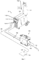
- FIG. 1 illustrates an example welding type system 10 including a welding-type power supply 100.
- a source of power is provided to the welding-type power supply 100 via an AC power cord 102. Typical ranges of AC power may be 115/230VAC or 208-600VAC, and may include single-phase or three-phase power.
- the welding-type power supply 100 generally supplies power for the welding-type system 10.
- Weld output 104 provides welding output power via one or more weld cables 106 coupled to a welding torch 116 and a workpiece 118 using a clamp 120.
- the welding-type power supply 100 includes a high-frequency transformer which is used to reduce or increase the voltage of incoming power so that it is usable for the particular welding-type application.
- the high-frequency transformer includes a primary and a secondary winding, or coil, around a metal core. Primary voltage, or input voltage enters the primary winding and creates a magnetic field that induces output voltage that is usable for the welding-type application.
- Welding-type output power provided by the welding-type power supply 100 may be in the range of 10 Amps to 600 amps or more, and range from substantially 0 volts in a short circuit condition to 44 volts or more into an open welding arc.
- Modern welding-type power supplies and systems can provide welding-type power for various welding-type processes which may include advanced waveform generation and control that is responsive to dynamic or static conditions at the welding arc.
- the illustrated welding type system includes a wire feeder 108 and a gas supply 110.
- the welding power supply 100 may provide power and control to other equipment such as a wire feeder 108.
- the welding torch 116 is coupled to the wire feeder 108 via coupler 122 in order to supply welding wire, shielding gas from the gas supply 110, and/or welding-type power to the welding torch 116 during operation of the welding-type system 10.
- the welding power source 100 may couple and/or directly supply welding-type power to the welding torch 116.
- the wire feeder 108 may require a certain type of power, for example, 24V or 50V for proper operation of the wire feeder 108 control circuits.
- the power for the wire feeder 108 may be provided by the welding power source 100 by a wire feeder 108 power supply circuit, or another type power circuit.
- one or more control signals may also be provided to allow proper operation of the wire feeder 108 and welding power source 100. These control signals may be analog or digital and may provide control and communication in a bi-directional manner.
- the power and control signals may be provided to the wire feeder 108 from the welding power source via cable(s) 106.
- the illustrated welding power source 100 has a control panel 112 with various types of control features 112, such as digital displays, control dials or potentiometers, control switches, LED indicators, etc. These control features 112 provide for normal operation and control of the welding system.
- FIG. 2 shows a block diagram of an example welding-type power supply 100.
- the power supply 100 includes an input circuit 201, an output circuit 202 and a high-frequency transformer 203.
- the transformer 203 includes a magnetic core 215 (e.g., a ferrite core).
- the core 215 may be selected to lower leakage inductance, for example based on the amount of turns used.
- the transformer 203 is connected between an output 204 of input circuit 201 and inputs 205 and 213 of the output circuit 202.
- the input circuit 201 is configured to receive an input signal from an external source of power at the input 206.
- Input signal and output signal as used herein include voltage signals, current signals and power signals.
- the input circuit 201 includes any circuit capable of receiving an input signal from a source of power and providing an output signal usable by a transformer.
- Input circuits can include as part of their circuitry, microprocessors, analog and digital controllers, switches, other transformers, rectifiers, inverters, converters, choppers, comparators, phased controlled devices, buses, pre-regulators, diodes, inductors, capacitors, or resistors.
- the output circuit 202 includes any circuit capable of receiving an input signal from a transformer and providing an output signal suitable for a desired purpose, such as welding-type output signal.
- Output circuits can include microprocessors, analog and digital controllers, switches, other transformers, rectifiers, inverters, converters, choppers, comparators, phased controlled devices, buses, pre-regulators, diodes, inductors, capacitors, or resistors.
- the input signal received at the input 206 is processed by the various circuitry of the input circuit 201 and the processed signal is provided to the transformer 203 via the output 204.
- the output signal from the input circuit 201 is received by the transformer 303 via the input 207 and transformed to the outputs 208, 212.
- the transformer 203 includes a primary coil 209 connected to the output 204 of input circuit 201 and a center tapped secondary coil 110 connected to the input 205 of output circuit 202.
- the secondary coil 210 is magnetically coupled with the primary coil 209.
- the primary coil 209 and the secondary coil 210 may have one or more insulative layers, for example, of FEP, ETFE, or PFA.
- the total distance through insulation of the primary coil 209 and the secondary coil 210 may comply with, for example, the IEC 60974-1 standard.
- the distance through insulation is at least .35 millimeters ("mm") where there are at least three layers of insulation between the primary coil 209 and the secondary coil 210.
- the distance through insulation is at least .4 mm where there are at least three layers of insulation between the primary coil 209 and the secondary coil 210.
- the distance through insulation is at least .5 mm where there are at least three layers of insulation between the primary coil 209 and the secondary coil 210.
- the power supply 100 also includes a boost coil 211 magnetically coupled with the primary coil 209.
- Boost coils may be used, for example, to maintain a welding arc during stick welding.
- the output 212 of the boost coil 212 is provided to the output circuit 202 via the input 213.
- the boost coil 211 may also include insulative layers, for example of FEP, ETFE, or PFA.
- the insulation of the boost coil 211 may comply with, for example, the IEC 60974-1 standard. However, the total distance through insulation may be modified to comply with different and/or additional standards.
- the secondary coil 210 of the transformer is not a tapped coil. In some examples, the secondary coil 210 is tapped at different locations such as quarter tapped or two-thirds tapped. In some examples, multiple secondary coils are provided such as two, three or four secondary coils, some or all of which may be connected to the output circuit 202.
- the output signal from the secondary coil 210 is received by the output circuit 202 at input 105.
- the input signal is processed by the various circuitry of output circuit 102 and the processed signal is provided at the output 214 as a signal suitable for a welding-type application.
- FIG. 3 illustrates a cross sectional view of a high-frequency transformer without an intermediate bobbin, for example the high-frequency transformer 203 of FIG. 2 .
- the primary winding 209 has 20 turns
- the secondary winding 210 has 5 turns.
- the windings 209 and 210 are arranged in a horizontal fashion.
- the secondary winding 210 has a diameter that is greater than the diameter of the primary winding 209, and the secondary winding 210 is arranged around, or surrounding the primary winding 209, in order to minimize leakage inductance.
- Other numbers of turns, other turn ratios, and/or other inter-turn and/or inter-winding spacing may be used.
- NE-F1 Underwriter's Laboratories approved insulation system for magnetic devices
- NE-F1 An example Underwriter's Laboratories approved insulation system for magnetic devices
- additional ground and interwinding insulation is not required to separate an insulated wire from other windings or between this winding and grounded metal for UL approval.
- an additional advantage of insulating the winding wire e.g., a filament wire
- additional ground and interwinding insulation is not necessary to satisfy UL requirements if insulated winding wire is used.
- DTI Distance through insulation
- the number of layers of insulation extruded onto the primary winding 209 plus the number of layers of insulation extruded onto the secondary winding 210 is at least three layers.
- the total DTI between the primary winding 209 and the secondary winding 210 in the example of FIG. 2 is at least 0.35 mm for RMS supply voltages of up to 440 V.
- the primary winding 209 and the secondary winding 210 are constructed to have a DTI of at least is 0.4 mm distributed among at least three insulation layers for RMS supply voltages of 441 V to 690 V, and are constructed to have a DTI of at least is 0.5 mm distributed among at least three insulation layers for RMS rated supply voltages of 691 V to 1000 V.
- a conventional intermediate bobbin has a DTI of at least 1.5 mm for RMS supply voltages of 441 V to 690 V and 2.0 mm for RMS rated supply voltages of 691 V to 1000 V.
- the DTI is smaller than conventional transformers that use intermediate bobbins, which enables more compact winding of the primary winding 209 and the secondary winding 210.
- the transformer 203 complies with the IEC 61558-1 standard. The entirety of the IEC 61558-1 standard, third edition, published September 29, 2017, is hereby incorporated by reference.
- the primary winding 209 may include three or more insulative layers, and the secondary winding 210 may have zero insulative layers.
- the IEC 60974-1 standard recites that the total number of insulative layers is at least three separate layers extruded onto the winding wires.
- the transformer 203 may comply with the IEC 60974-1 standard.
- the secondary winding 210 may include three or more insulative layers, and the primary winding 209 may have zero insulative layers.
- the winding with zero insulative layers i.e., layers of Teflon® type insulation, including FEP, ETFE, or PFA insulation
- the primary winding 209 may have two or more insulative layers, and the secondary winding 210 has one insulative layer. In some examples, the secondary winding 210 may have two or more insulative layers, and the primary winding 209 has one insulative layer. In some examples, both the primary winding 209 and the secondary winding 210 have two insulative layers.
- each extruded insulative layer is at least .4/3 mm thick.
- the windings 209 and 210 comply with the IEC 60974-1 standard.
- additional windings are included in the transformer 203, for example the boost winding 211.
- the total number of insulative layers between any two windings is at least three separate insulative layers.
- the DTI between any the primary winding 209, the secondary winding 210, and the boost winding 211 is: .35 mm for RMS rated supply voltages up to 440 V; .4 mm for RMS rates supply voltages between 441 V and 690 V; and .5 mm for RMS rated supply voltages between 691 V and 1000 V.
- the number of insulative layers on each winding (209, 210, and 211) is at least two such that the total number of insulative layers between any two windings will exceed three layers. In some examples, each insulative layer is at least .0875 mm thick.
- the primary coil 209 and the secondary coil 210 are wound with two sections in a horizontal manner to manage the lead exits, keep the coil internal thermal conduction resistance to a minimum, and to minimize the number of leads to prepare.
- the secondary turns 210 do not fill the window 302, which dictates that the secondary winding 210 should be placed around (i.e., outside of) the primary winding 209.
- a total number of extruded insulative layers of the primary winding 209 and the secondary winding 210 is at least three layers. The insulative layers also insulate the windings 209 and/or 210 from the metal core 215, which may obviate a need for a coil cover 304.
- a coil cover 304 may be included to facilitate lead anchoring and winding spacing.
- a coil cover 304 may compress the windings 209 and/or 210 to lower thermal contact resistance.
- a coil cover 304 may be omitted, which may reduce the total cost of the transformer 203 and increase the usable area of the window 302.
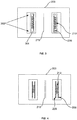
- FIG. 4 illustrates a transformer 400 which includes three winding sections as one winding (e.g., the primary winding 209) is split into two parts. Leakage inductance may be reduced by splitting one of the windings (e.g., the primary winding 209) into two sections.
- This type of winding arrangement may require more complexity and/or cost as compared to the horizontal winding arrangement of FIG. 3 . For example, splitting a winding may require more winding leads.
- both the primary and the secondary windings may be split (e.g., there may be four or more winding sections.)
- at least one of the windings 209 or 210 may be split into more than two sections.
- the windings may be sectionalized in a vertical arrangement.
- the number of turns may be reduced and two winding sections may be used (as shown in FIG. 3 ).
- the core cross section is independent of the number of winding sections.
- the primary winding 209 and the secondary winding 210 may be wound bi-filar.
- the wires of the primary winding 209 and the secondary winding 210 are wound side-by-side.
- a larger diameter winding wire may be split into smaller wires in parallel.
- a bi-filar arrangement may provide a lower leakage inductance, but also may increase the complexity of winding lead exits.
- the windings 209 and 210 may be arranged in vertical sections 502 and 504.
- a vertical arrangement may include wedges on the sides of the wire to compress the sections of wire against each other to achieve low leakage inductance.
- Conventional high-frequency transformers that use a vertical arrangement typically include a molded-in barrier in the bobbin having a thickness of greater than 1.5 mm.
- This vertical section barrier obviates the need to have insulation extruded onto the wire, but results in a higher leakage inductance as well as a requirement to manage the winding lead exits.
- a vertical arrangement without extruded insulation may also require a coil cover to insulate the wire winding from the metal core. If insulated winding wire is used, as described in the present disclosure, a bobbin and the corresponding molded-in barrier may be omitted.
- each of the primary and secondary windings (209 and 210 of FIG. 2 ) may be a conductor 602 made of stranded or bunched wire, meaning that each winding coil may include multiple wires 604.
- each individual wire 604 within the conductor include an enamel covering.
- the primary and secondary windings are Litz wires (i.e., stranded wires that are twisted or braided, and which may be individually insulated). In other words, the Litz wires generally reduce AC losses in high frequency windings.
- one or more of the windings 209 and 210 may be generally flat or rectangular.
- the strands 604 of wire that make up a winding are not twisted and are bunched together and placed in parallel.
- insulative layers 606 may be place around the conductor 602 (e.g., extruded onto the conductor 604), where the conductor 602 may include multiple wires 604.
- the insulative layers 606 may comply with the IEC 60974-1 standard.
- the present methods and/or systems may be realized in hardware, software, or a combination of hardware and software.
- the present methods and/or systems may be realized in a centralized fashion in at least one computing system, or in a distributed fashion where different elements are spread across several interconnected computing systems. Any kind of computing system or other apparatus adapted for carrying out the methods described herein is suited.
- a typical combination of hardware and software may be a general-purpose computing system with a program or other code that, when being loaded and executed, controls the computing system such that it carries out the methods described herein.
- Another typical implementation may comprise an application specific integrated circuit or chip.
- Some implementations may comprise a non-transitory machine-readable (e.g., computer readable) medium (e.g., FLASH drive, optical disk, magnetic storage disk, or the like) having stored thereon one or more lines of code executable by a machine, thereby causing the machine to perform processes as described herein.
- a non-transitory machine-readable (e.g., computer readable) medium e.g., FLASH drive, optical disk, magnetic storage disk, or the like
- "and/or” means any one or more of the items in the list joined by “and/or”.
- "x and/or y” means any element of the three-element set ⁇ (x), (y), (x, y) ⁇ . In other words, “x and/or y” means “one or both of x and y”.
- "x, y, and/or z” means any element of the seven-element set ⁇ (x), (y), (z), (x, y), (x, z), (y, z), (x, y, z) ⁇ . In other words, "x, y and/or z” means “one or more of x, y and z”.
- the term "exemplary” means serving as a non-limiting example, instance, or illustration.
- the terms "e.g.,” and “for example” set off lists of one or more non-limiting examples, instances, or illustrations.
- block and/or components of disclosed examples may be combined, divided, re-arranged, and/or otherwise modified.
- many modifications may be made to adapt a particular situation or material to the teachings of the present disclosure without departing from its scope. Therefore, the present method and/or system are not limited to the particular implementations disclosed. Instead, the present method and/or system will include all implementations falling within the scope of the appended claims, both literally and under the doctrine of equivalents.
Landscapes
- Engineering & Computer Science (AREA)
- Power Engineering (AREA)
- Coils Of Transformers For General Uses (AREA)
Applications Claiming Priority (1)
| Application Number | Priority Date | Filing Date | Title |
|---|---|---|---|
| US16/537,065 US20210043374A1 (en) | 2019-08-09 | 2019-08-09 | Insulated winding wire transformer for welding-type power supplies |
Publications (1)
| Publication Number | Publication Date |
|---|---|
| EP3780029A1 true EP3780029A1 (fr) | 2021-02-17 |
Family
ID=71950456
Family Applications (1)
| Application Number | Title | Priority Date | Filing Date |
|---|---|---|---|
| EP20189520.8A Pending EP3780029A1 (fr) | 2019-08-09 | 2020-08-05 | Transformateur de fil à enroulement isolé pour alimentations électriques de type soudage |
Country Status (3)
| Country | Link |
|---|---|
| US (1) | US20210043374A1 (fr) |
| EP (1) | EP3780029A1 (fr) |
| CN (1) | CN112349498A (fr) |
Citations (10)
| Publication number | Priority date | Publication date | Assignee | Title |
|---|---|---|---|---|
| EP0033224A1 (fr) * | 1980-01-24 | 1981-08-05 | Sumitomo Electric Industries Limited | Fil d'enroulement magnétique |
| US20010010269A1 (en) * | 2000-01-25 | 2001-08-02 | Atsushi Higashiura | Multilayer insulated wire and transformer using the same |
| US6611189B2 (en) * | 2001-05-22 | 2003-08-26 | Illinois Tool Works Inc. | Welding power supply transformer |
| US6794976B2 (en) * | 2002-12-24 | 2004-09-21 | Illinois Tool Works Inc. | HF transformer assembly having a higher leakage inductance boost winding |
| US20140225704A1 (en) * | 2012-03-27 | 2014-08-14 | Furukawa Electric Co., Ltd. | Multilayer insulated electric wire and electric or electronic equipment using the same |
| US20150235736A1 (en) * | 2012-11-30 | 2015-08-20 | Furukawa Magnet Wire Co., Ltd. | Insulated wire and electric or electronic equipment |
| EP2991081A1 (fr) * | 2013-04-26 | 2016-03-02 | Furukawa Electric Co., Ltd. | Fil isolé et équipement électrique et électronique, moteur, et transformateur l'utilisant |
| EP3382724A1 (fr) * | 2017-03-30 | 2018-10-03 | Sumida Corporation | Dispositif de transformateur |
| WO2019018213A1 (fr) * | 2017-07-19 | 2019-01-24 | Essex Group, Inc. | Systèmes et procédés pour former une isolation de fil de bobinage avec un matériau thermodurcissable |
| CN110085399A (zh) * | 2019-05-29 | 2019-08-02 | 江苏容天机电科技有限公司 | 一种高频高压等离子变压器 |
Family Cites Families (9)
| Publication number | Priority date | Publication date | Assignee | Title |
|---|---|---|---|---|
| US4694140A (en) * | 1985-11-14 | 1987-09-15 | Wheeler William M | AC power supply |
| JPH02250207A (ja) * | 1989-03-23 | 1990-10-08 | Fujikura Ltd | 絶縁電線 |
| JPH05175059A (ja) * | 1991-12-21 | 1993-07-13 | Totoku Electric Co Ltd | 変圧器 |
| JPH08115828A (ja) * | 1994-10-14 | 1996-05-07 | Matsushita Electric Ind Co Ltd | マグネトロン駆動用電源 |
| US6046664A (en) * | 1998-03-05 | 2000-04-04 | Century Manufacturing Company | Welding power supply transformer apparatus and method |
| JP2004119811A (ja) * | 2002-09-27 | 2004-04-15 | Toshiba Corp | 静止誘導電気機器 |
| JP5679754B2 (ja) * | 2010-05-06 | 2015-03-04 | 株式会社ダイヘン | 直流抵抗溶接機用トランス |
| CN203774075U (zh) * | 2014-01-22 | 2014-08-13 | 北京新创四方电子有限公司 | 一种环形印刷线路板焊接式电源变压器 |
| JP6490620B2 (ja) * | 2016-04-22 | 2019-03-27 | 古河電気工業株式会社 | 巻線、コイル及びトランス |
-
2019
- 2019-08-09 US US16/537,065 patent/US20210043374A1/en not_active Abandoned
-
2020
- 2020-08-05 EP EP20189520.8A patent/EP3780029A1/fr active Pending
- 2020-08-06 CN CN202010784240.0A patent/CN112349498A/zh active Pending
Patent Citations (10)
| Publication number | Priority date | Publication date | Assignee | Title |
|---|---|---|---|---|
| EP0033224A1 (fr) * | 1980-01-24 | 1981-08-05 | Sumitomo Electric Industries Limited | Fil d'enroulement magnétique |
| US20010010269A1 (en) * | 2000-01-25 | 2001-08-02 | Atsushi Higashiura | Multilayer insulated wire and transformer using the same |
| US6611189B2 (en) * | 2001-05-22 | 2003-08-26 | Illinois Tool Works Inc. | Welding power supply transformer |
| US6794976B2 (en) * | 2002-12-24 | 2004-09-21 | Illinois Tool Works Inc. | HF transformer assembly having a higher leakage inductance boost winding |
| US20140225704A1 (en) * | 2012-03-27 | 2014-08-14 | Furukawa Electric Co., Ltd. | Multilayer insulated electric wire and electric or electronic equipment using the same |
| US20150235736A1 (en) * | 2012-11-30 | 2015-08-20 | Furukawa Magnet Wire Co., Ltd. | Insulated wire and electric or electronic equipment |
| EP2991081A1 (fr) * | 2013-04-26 | 2016-03-02 | Furukawa Electric Co., Ltd. | Fil isolé et équipement électrique et électronique, moteur, et transformateur l'utilisant |
| EP3382724A1 (fr) * | 2017-03-30 | 2018-10-03 | Sumida Corporation | Dispositif de transformateur |
| WO2019018213A1 (fr) * | 2017-07-19 | 2019-01-24 | Essex Group, Inc. | Systèmes et procédés pour former une isolation de fil de bobinage avec un matériau thermodurcissable |
| CN110085399A (zh) * | 2019-05-29 | 2019-08-02 | 江苏容天机电科技有限公司 | 一种高频高压等离子变压器 |
Also Published As
| Publication number | Publication date |
|---|---|
| US20210043374A1 (en) | 2021-02-11 |
| CN112349498A (zh) | 2021-02-09 |
Similar Documents
| Publication | Publication Date | Title |
|---|---|---|
| EP1434241B1 (fr) | Transformateur à haute fréquence comportant un enroulement élévateur de tension à inductance de fuite augmentée | |
| EP2237641B1 (fr) | Dispositif de chauffage par induction électromagnétique | |
| EP1160801B1 (fr) | Ensemble câble multiconducteur à haute fréquence et équipment d'alimentation électique pour un ou plusieurs corps mobiles utilisant un tel câble | |
| EP3398249B1 (fr) | Alimentation électrique de soudage à circuits inverseurs entrelacés | |
| EP3780029A1 (fr) | Transformateur de fil à enroulement isolé pour alimentations électriques de type soudage | |
| US12469637B2 (en) | High-frequency transformers using solid wire for welding-type power supplies | |
| US11160144B2 (en) | Modular transformers and induction heating systems having modular transformers | |
| CA2962456C (fr) | Alimentation electrique du type pour soudage a transformateur de soudage | |
| US20250125080A1 (en) | Low-leakage planar transformers for welding-type power supplies | |
| US20250182955A1 (en) | Low-leakage overmolded planar transformers for welding-type power supplies | |
| US10486257B2 (en) | Welding type power supply with transformer | |
| US11660697B2 (en) | Balanced plate rectifiers and welding-type power supplies including balanced plate rectifiers | |
| KR200241161Y1 (ko) | 2φ 스틸 및 알루미늄겸용 탄산가스 마그/미그 용접기용전원 공급장치 | |
| EP3503133A1 (fr) | Agencement de transformateur | |
| JPH01258388A (ja) | マグネトロン用インバータ電源 | |
| KR20110134124A (ko) | 용접기용 단상 변압기 | |
| JPH0566943U (ja) | インバータ電源用高圧トランス |
Legal Events
| Date | Code | Title | Description |
|---|---|---|---|
| PUAI | Public reference made under article 153(3) epc to a published international application that has entered the european phase |
Free format text: ORIGINAL CODE: 0009012 |
|
| STAA | Information on the status of an ep patent application or granted ep patent |
Free format text: STATUS: THE APPLICATION HAS BEEN PUBLISHED |
|
| AK | Designated contracting states |
Kind code of ref document: A1 Designated state(s): AL AT BE BG CH CY CZ DE DK EE ES FI FR GB GR HR HU IE IS IT LI LT LU LV MC MK MT NL NO PL PT RO RS SE SI SK SM TR |
|
| AX | Request for extension of the european patent |
Extension state: BA ME |
|
| STAA | Information on the status of an ep patent application or granted ep patent |
Free format text: STATUS: REQUEST FOR EXAMINATION WAS MADE |
|
| 17P | Request for examination filed |
Effective date: 20210816 |
|
| RBV | Designated contracting states (corrected) |
Designated state(s): AL AT BE BG CH CY CZ DE DK EE ES FI FR GB GR HR HU IE IS IT LI LT LU LV MC MK MT NL NO PL PT RO RS SE SI SK SM TR |
|
| STAA | Information on the status of an ep patent application or granted ep patent |
Free format text: STATUS: EXAMINATION IS IN PROGRESS |
|
| 17Q | First examination report despatched |
Effective date: 20230412 |