EP3780064B1 - Correcteur optique à particules sans erreurs axiales de sixième ordre et microscope électronique pourvu d'un correcteur - Google Patents
Correcteur optique à particules sans erreurs axiales de sixième ordre et microscope électronique pourvu d'un correcteur Download PDFInfo
- Publication number
- EP3780064B1 EP3780064B1 EP20186011.1A EP20186011A EP3780064B1 EP 3780064 B1 EP3780064 B1 EP 3780064B1 EP 20186011 A EP20186011 A EP 20186011A EP 3780064 B1 EP3780064 B1 EP 3780064B1
- Authority
- EP
- European Patent Office
- Prior art keywords
- corrector
- lenses
- electron microscope
- hexapole
- round
- Prior art date
- Legal status (The legal status is an assumption and is not a legal conclusion. Google has not performed a legal analysis and makes no representation as to the accuracy of the status listed.)
- Active
Links
Images




Classifications
-
- H—ELECTRICITY
- H01—ELECTRIC ELEMENTS
- H01J—ELECTRIC DISCHARGE TUBES OR DISCHARGE LAMPS
- H01J37/00—Discharge tubes with provision for introducing objects or material to be exposed to the discharge, e.g. for the purpose of examination or processing thereof
- H01J37/02—Details
- H01J37/04—Arrangements of electrodes and associated parts for generating or controlling the discharge, e.g. electron-optical arrangement or ion-optical arrangement
- H01J37/153—Electron-optical or ion-optical arrangements for the correction of image defects, e.g. stigmators
-
- H—ELECTRICITY
- H01—ELECTRIC ELEMENTS
- H01J—ELECTRIC DISCHARGE TUBES OR DISCHARGE LAMPS
- H01J37/00—Discharge tubes with provision for introducing objects or material to be exposed to the discharge, e.g. for the purpose of examination or processing thereof
- H01J37/26—Electron or ion microscopes; Electron or ion diffraction tubes
-
- H—ELECTRICITY
- H01—ELECTRIC ELEMENTS
- H01J—ELECTRIC DISCHARGE TUBES OR DISCHARGE LAMPS
- H01J2237/00—Discharge tubes exposing object to beam, e.g. for analysis treatment, etching, imaging
- H01J2237/153—Correcting image defects, e.g. stigmators
- H01J2237/1534—Aberrations
Definitions
- the invention relates to a particle-optical corrector for correcting the spherical aberration of an electron microscope while avoiding the three-fold axial astigmatism, the fourth-order axial three-lobe error and the six-fold axial astigmatism, the corrector having a central multipole element of length L for generating a hexapole field in the plane of symmetry of the corrector and two outer identical multipole elements of length L ' for generating equally strong hexapole fields and two round lens doublets with round lenses, the round lenses closer to the plane of symmetry being arranged at a distance of the focal lengths of the round lenses from the plane of symmetry, and the round lenses further away from the plane of symmetry being at a distance from the latter corresponds to their focal lengths plus the focal lengths of the circular lenses that are closer to the plane of symmetry.
- Electron-optical imaging systems are used both for enlargement, as in the case of electron microscopy, and for reduction in electron projection lithography.
- the advantage over light-optical imaging systems is their significantly higher resolution, which results from the significantly lower wavelength of the imaging optical radiation.
- electron-optical imaging systems improve the resolution by a factor of about 10 4 depending on the acceleration voltage, so that images down to the atomic range are possible.
- Electron beams are guided for the purpose of imaging with the aid of electric and/or magnetic lenses.
- lens systems are afflicted with different image errors to a greater extent than light-optical systems.
- particle-optical correctors The purpose of particle-optical correctors is to compensate for aperture errors and, if applicable, chromatic errors in the optical components of the microscope. through the Compensation by means of such correctors, however, errors are also caused by the corrector itself.
- Correcting errors means that the corrector produces errors that oppose the errors of the optical system and thereby compensate for them. However, it is the case that such correctors also produce errors themselves, which must also be compensated for as far as possible within the corrector.
- the geometric errors deform the wave fronts of the light or, in particle optics, the particle beams into a non-spherical shape, with the corrector having to restore this shape to the greatest possible extent or deform it in such a way that it becomes spherical again after the occurrence of subsequent errors.
- Rolf Erni ibid., pages 214 - 228, chapter "7.5 Wave Surface, Aberration Function and Image Aberrations").
- Spherical aberration correctors which avoid residual axial errors up to the fifth order. However, if these correctors are corrected up to the fifth order, a sixth-order three-lobe error becomes so dominant that it unacceptably disturbs the image quality when the objective aperture is opened further.
- the known correctors are those with two or three hexapoles with interposed circular lens doublets.
- the correctors with two hexapoles are the corrector EP 0 451 370 B1 (Rose ) as well as further developments of this corrector, for example Müller H., Uhlemann S., Hartel P., and Haider M. (2006) "Advancing the Hexapole Cs-corrector for the scanning transmission electron microscope.” Microsc. Microanal. 12:442-455 .
- a corrector with three hexapoles is for example the one from the EP 3 255 649 A1 or from the DE 10 2006 017 686 A1 known.
- the delta corrector Sawada et. al. "Correction of higher order geometrical aberration by triple 3-fold astigmatism field", Journal of Electron Microscopy 58(6): 341 - 347 (2009 )).
- the delta corrector is a corrector of the type mentioned above, with which the spherical aberration (C s ) is corrected while avoiding the axial astigmatism (A 2 ), the fourth-order axial three-lobe aberration (D 4 ) and the six-fold axial astigmatism (A 5 ) can be corrected, but not the sixth-order three-lobe error (D 6 ).
- C s spherical aberration
- D 4 fourth-order axial three-lobe aberration
- a 5 six-fold axial astigmatism
- the invention is therefore based on the object of making a spherical aberration corrector available which avoids all out-of-round axial errors up to the fifth order and the sixth-order three-lobe error without introducing errors which again nullify the improvement achieved thereby.
- the object is achieved with a particle-optical corrector of the type mentioned at the outset in that the strength of the central hexapole field is selected in relation to the strengths of the two equally strong outer hexapole fields in such a way that the three-fold axial astigmatism disappears and the strengths of the latter are selected in such a way that the corrector overall has no six-fold axial astigmatism, that the distance between the multipole elements and the circular lenses further away from the plane of symmetry corresponds to their focal length plus a further distance, the latter being selected in such a way that for the given lengths of the central multipole element and the given lengths of the identical multipole elements fourth-order axial trilobe error disappears, and that the length of the central multipole element in relation to the lengths of the two outer identical multipole elements is chosen such that the sixth-order axial trilobe error - for the given focal length ratio d he circular lenses that are closer to the plane of symmetry to the focal length of the circular lenses that are further away from the plane of
- the starting point of the invention is that the internal combination errors of the three-fold axial astigmatism (A 2 ) and the fourth-order axial three-lobe error (D 4 ) with the hexapole field on the one hand and the six-fold axial astigmatism (A 5 ) with the hexapole field on the other hand must eliminate each other .
- This is to be understood as meaning that the beam is first deformed by a hexapole field and then made round again by a subsequent hexapole field.
- undesired errors that are already present are eliminated, and on the other hand, the same errors are generated with the opposite sign for the subsequent compensation to compensate for subsequent errors.
- this deformation and re-rounding takes place as follows: the beam enters the first multipole element, is deformed there and in the first half (before the plane of symmetry) of the central multipole element after an error compensation of the type mentioned above again rounded. In the second half of the central multipole element (after the plane of symmetry) the beam is deformed again in order to be made round again in the second multipole element, which is identical to the first one. There, too, errors are compensated for in the non-round beam area.
- the further goal is to focus the beam into the sample with this freedom from errors with the largest possible aperture angle ( ⁇ ) in order to keep the diffraction limitation low.
- the measure of the diffraction limitation is ⁇ / ⁇ .
- the angle ⁇ is much larger than in electron microscopy.
- the fact that the latter has a much lower diffraction limitation is due to the fact that the wavelength ⁇ is much smaller for electron beams than for light waves.
- the ratio of the hexapole strengths i.e. the strength of the central multipole ( ⁇ HP2 ) to the strengths ( ⁇ HP1,3 ) of the other two outer identical multipole elements.
- ⁇ HP2 the strength of the central multipole
- ⁇ HP1,3 the strengths of the other two outer identical multipole elements.
- the strengths of the outer hexapole fields must be selected in such a way that the corrector as a whole does not have a six-fold axial astigmatism.
- the ratio d of the extent of the further distance of the center planes of the outer identical hexapoles to the focal planes of the outer transfer lenses (7", 8") ⁇ z to the length L ' of the outer identical multipole elements (1, 3) is relevant.
- the strength of the hexapole fields ⁇ results from the number of turns N multiplied by the current intensity I.
- this feature of freedom from fourth-order three-lobe errors (D 4 ) must also be fulfilled.
- the two outer hexapole fields are in the focal lengths of the outer round lenses - compared to the plane of symmetry - but the outer hexapole elements are there to ensure freedom from the axial three-lobe error fourth order (D 4 ) rotated against each other (see the above-mentioned paper by Morishita et. al., there p. 158, Fig. 1b).
- ⁇ D 6 x a 3 ⁇ ⁇ e.g ⁇ X ⁇ A 2 ⁇ e.g ⁇ X ⁇ D 4 ⁇ e.g ⁇ and a e.g double
- X ⁇ A 2 ⁇ , X ⁇ D4 ⁇ and X ⁇ A5 ⁇ are the error trajectories of errors
- a 2 , D 4 and A 5 and u ⁇ is the axial fundamental trajectory coming from the radiation source and focused into the object plane by the objective lens becomes.
- the y-components of the vectors are negligible due to the identical orientation of the hexapoles (in contrast to the delta corrector).
- the three ratios mentioned above are linked to one another, and it is important to find values that fulfill the three conditions mentioned.
- the fulfillment of the theoretical conditions must of course still be adapted to the specific conditions for specific electron microscopes, which are different depending on the requirements and application and show deviations from the theoretical calculation due to construction errors.
- a beam path as claimed and by means of an embodiment in 1 drawn, is the theory and thus an ideal that cannot be achieved in practice because every part production always has errors, even if they are very minor.
- correctors are extremely sensitive systems that deviate from their intended function even with the slightest error. If one were therefore only to use parts for which a maximum of mechanical freedom from defects could be achieved, one would have a large number of rejected parts, which would be very uneconomical.
- the unwanted parasitic errors indicate in which direction the correction should be made.
- the extent of the correction is then result-oriented.
- the ratio of the strength of the hexapole field ⁇ HP2 of the central multipole element 2 to the strength ⁇ HP1,3 , i.e., ⁇ HB 2 ⁇ HB 1.3 , is preferably in a range from 0.33 to 1.7.
- a further development of the corrector according to the invention serves to compensate for construction errors, with errors being generated which compensate for the errors caused by construction errors.
- the planes of symmetry of hexapole doublets additionally arranged between the round lenses of the round lens doublets are arranged at the distance of their focal lengths from the round lenses lying closer to the plane of symmetry and at the distance of their focal lengths from the round lenses lying further away from the plane of symmetry, with the hexapole doublets being arranged in such a are constructed and excited so that small variations of the fourth order three-lobe error can be generated within the corrector to compensate for errors of reversed sign caused by construction errors.
- the invention further relates to an electron microscope equipped with the corrector described above.
- This is preferably a scanning electron microscope (SEM) or a scanning transmission electron microscope (STEM).
- TEM transmission electron microscope
- a transfer lens system is expediently inserted between the corrector and the objective lens, with which spherical aberrations can be corrected.
- a transfer lens system can consist of either one or two transfer lenses.
- the transfer lens system with two transfer lenses is expediently designed in such a way that the transfer lenses have such different focal lengths that the objective lens aperture errors can be eliminated. Provision can be made for the focal lengths of the transfer lenses to be adjustable by means of the excitation of the coils of the transfer lenses in order to eliminate the specific objective lens aperture errors.
- FIG. 1 An exemplary embodiment of a particle-optical corrector 5 according to the invention and an exemplary embodiment of a transfer lens system 11 added according to a further development are shown.
- the installation in an electron microscope is illustrated fragmentarily by the optical axis 4, the condenser lens 16 and an objective lens 13 with two objective lens fields 13', 13" with the focal lengths f ⁇ as well as by the detector 15, which is used for image generation in a scanning electron microscope, intermediate lenses are intermediate lenses omitted.
- the sample 14 is located between the objective lens fields 13 and 13'.
- the objective lens 13 can also have only one objective lens field, behind which the sample is located.
- u ⁇ shows the on-axis beam path and u ⁇ the off-axis beam path.
- the corrector 5 consists of three multipole elements 1, 2 and 3, a central multipole element 2, which lies in the plane of symmetry 6 of the corrector 5, and two outer multipole elements 1 and 3, which are identical.
- the central multipole element 2 has a hexapole field of strength ⁇ HP2 and a length L.
- the two outer multipole elements 1 and 3 have hexapole fields of strength ⁇ HP1,3 and a length L '.
- Circular lens doublets 7 and 8 with the circular lenses 7', 7" and 8', 8" are arranged between the multipole elements 1, 2 and 3.
- the circular lenses 7' and 8' are arranged at the distance of their focal lengths f from the plane of symmetry 6, and the circular lenses 7" and 8" with the focal lengths f ' have the distance of both focal lengths f and f ' from the circular lenses 7' and 8'.
- the outer, identical multipole elements 1 and 3 are distant from the round lenses 7" and 8" by their focal length f ' plus a dimension ⁇ z , with these distances respectively being on the planes of symmetry 1', 6 and 3' of the hexapole elements 1, 2 and 3 relate, or also in the case of the round lenses to their planes of symmetry.
- the ratio of the strength of the hexapole field ⁇ HP2 of the central multipole element 2 to the strengths of the hexapole fields ⁇ HP1,3 of the outer multipole elements 1, 3 is such that the three-fold astigmatism A 2 has disappeared.
- the dimension ⁇ z is selected according to the invention in such a way that for predetermined lengths L and L ′ of the multipole elements 1, 2 and 3, the fourth-order axial three-lobe error D 4 disappears.
- a beam coming from the radiation source and bundled by condenser lens(es) enters round, which is represented by the axial beam path u ⁇ and the off-axis beam path u ⁇ .
- the beam is first deformed by the first outer multipole element 1 and made round again in the first half of the central multipole element 2, then deformed again in threefold in the second half of multipole element 2 and made round again with the third outer multipole element 3.
- O. Scherzer see above
- the non-circular beam areas are used for the described error correction. This is the basis of the particle-optical corrector 5 according to the invention.
- additional hexapole doublets 9, 9' and 10, 10' which are arranged between the circular lenses 7' and 7" and 8' and 8" of the circular lens doublets 7 and 8, with their planes of symmetry 9", 10" being separated from the circular lenses 7 ', 7", 8', 8" each have a distance which corresponds to their focal lengths f, f '.
- the drawing also shows a transfer lens system 11, which is connected downstream of the corrector and has two transfer lenses 11' and 11". These have such different focal lengths f" and f′′′ that the aperture errors of the objective lens 13 can be eliminated.
- the focal lengths f", f ′′′ can be varied within a certain range by exciting the coils of the transfer lenses 11' and 11". The elimination of spherical aberrations must take place before the beam impinges on the sample 14.
- Electromagnets 12, 12' for deflecting the scanning beam can be arranged in the transfer lens system 11 for a scanning electron microscope.
- Figures 2a, 2b and 2c show representations of error compensations of the prior art and the invention based on vectors a, b and c.
- the vector a is created by the errors A 2 and D 4 in the hexapole field and the vector b by the error A 5 in the hexapole field.
- the vector c is the resultant of the vectors a and b and gives the error D 6 .
- the Figure 2a shows how in Rose (see above) the resultant c results from the vectors a and b.
- This resultant arises here because the combination error from A 2 and D 4 , which makes up vector a, and the small combination error from A 5 of vector b cannot compensate each other.
- the vector c is about as large as the vector a, which already causes the entire error D 6 .
- the Figure 2b shows the same with the delta corrector (see above), where there is a resulting error D 6 because the vectors a and b partially point in the same direction.
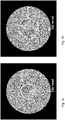
- the Figures 3a to 3 i each show Ronchigrams, which are bright field images of round bundles of rays that are used for imaging, for example the rays of a scanning electron microscope that would scan the object.
- a central area can be seen which, due to the very high magnification (image with an almost punctiform focused probe), has no structures. This means that the focus of this central aperture area is almost ideal.
- This area is surrounded by essentially hexagonal structures.
- the outer aperture areas are namely imaged in 3 or 6-fold tails of the focused probe, so that larger areas of the object (assumed to be amorphous) are hit, i.e. the magnification decreases, whereby structures become visible.
- Figure 3a a Ronchigram of the corrector according to Müller et al. (2006 - see above). It is a two-hexapole corrector without optimization. The flawless aperture of the beam is 50 mrad.
- Figure 3b shows a Ronchigram of the same corrector in an optimized state, with the error-free aperture of the beam having 68 mrad.
- EP 3c shows a Ronchigram of the EP 2 325 862 A1 or.
- EP 2 325 863 B1 (each from S. Henstra - see above) known two-hexapole corrector with double normal excitation of the hexapoles and the additional multipole with the reference number 126.
- the error-free aperture of the beam is 45 mrad.
- 3d shows a Ronchigram of this corrector with optimization of the phase shift, whereby an error-free aperture of 64 mrad is achieved.
- Figure 3e shows the Henstra corrector acc. 3c and 3d with the additional twelve-pole with the reference numeral 128. Due to the rim error (G 7 ) introduced by the twelve-pole, the error-free aperture is only 44 mrad.
- the Figures 3f and 3g show the above delta corrector with and without compensation, achieving error-free apertures of 50 mrad and 70 mrad.
Landscapes
- Chemical & Material Sciences (AREA)
- Analytical Chemistry (AREA)
- Electron Beam Exposure (AREA)
- Analysing Materials By The Use Of Radiation (AREA)
Claims (18)
- Correcteur optique des particules (5) pour la correction des erreurs d'ouverture (C3, C5) d'un microscope électronique en évitant l'astigmatisme axial à trois chiffres (A2), de l'erreur trilobée axiale de quatrième ordre (D4) et de l'astigmatisme axial à six chiffres (A5), sachant que le correcteur (5) comporte un élément de multipôles central (2) de longueur L pour générer un champ d'hexapôles (Ψ HPZ ) dans le plan de symétrie (6) du correcteur (5) ainsi que deux éléments de multipôles identiques extérieurs (1, 3) de longueur L' pour générer des champs d'hexapôles de même puissance ((Ψ HP1, Ψ HP3 ) et deux doublets de lentilles rondes (7 et 8) avec des lentilles rondes (7', 7", 8', 8"), sachant que les lentilles rondes (7' et 8') plus proches du plan de symétrie (6) sont disposées par rapport au plan de symétrie (6) à distance des distances focales (f) des lentilles rondes (7', 8') et les lentilles rondes (7", 8") plus éloignées par rapport au plan de symétrie (6) de ce dernier comporte une distance qui correspond à leurs distances focales (f') en plus des distances focales (f) des lentilles rondes (7', 8'), qui se situent plus près du plan de symétrie (6)
caractérisé en ce que
la puissance du champ d' hexapôles central (Ψ HPZ ) est choisi par rapports aux puissances des deux champs d' hexapôles extérieurs de même puissance (Ψ HP1,3 ) de telle manière que l'astigmatisme axial à trois chiffres (A2) disparaît et les puissances (Ψ HP1,3 ) de ces derniers sont choisis de telle sorte que le correcteur (5) n'a dans l'ensemble aucun astigmatisme axial à six chiffres (A5), que la distance des éléments multipôles (1 et 3) des lentilles rondes (7", 8") plus éloignées du plan de symétrie (6), correspond à la distance focale (f') de ceux-ci en plus d'une autre distance ( Δz ), sachant que cette dernière est choisie de telle manière que pour les longueurs données L et L', l'erreur trilobée axiale de quatrième ordre (D4) disparaît et que la longueur (L) de l'élément de multipôles central (2) est choisie par rapport aux longueurs (L') des deux éléments de multipôles extérieurs identiques (1 et 3) de telle manière que l'erreur trilobée axiale de sixième ordre (D6) disparaît pour le rapport prédéfini (M = f / f') de la distance focale (f') des lentilles rondes (7', 8') plus proches du plan de symétrie (6) par rapport à la distance focale (f') des lentilles rondes (7", 8") plus éloignées du plan de symétrie (6). - Correcteur selon la revendication 1,
caractérisé en ce que
le rapport (d) entre l'autre distance (ΔZ) et les longueurs (L') des éléments de multipôles extérieurs (1 et 3) est de 0,5 à 0,95 (
- Correcteur selon la revendication 1 ou 2,
caractérisé en ce que
la puissance du champ d'hexapôles (Ψ HP2 ) de l'élément multipôle central (2) par rapport à la puissance des champs d' hexapôles (Ψ HP1,3 ) extérieurs (1,3) se situe de 0,33 à 1,7
- Correcteur selon l'une quelconque des revendications 1 à 3,
caractérisé en ce que
le rapport (M) entre les distances focales (f) des lentilles rondes (7', 8') situées plus près sur le plan de symétrie (6) et les distances focales (f') des lentilles rondes (7", 8") situées plus éloignées, donc M = f / f', se situe dans une plage de 0,8 à 1,2. - Correcteur selon la revendication 4,
caractérisé en ce que
- Correcteur selon l'une quelconque des revendications 1 à 5,
caractérisé en ce que
le rapport (k) entre la longueur (L) de l'élément de multipôles central (2) et la longueur (L') des multipôles extérieurs (1 et 3), donc k = L / L', se situe dans une plage de 2,0 à 3,5. - Correcteur selon la revendication 6,
caractérisé en ce que
- Correcteur selon l'une quelconque des revendications 1 et 7,
caractérisé en ce que
les plans de symétrie (9" et 10") des doublets d'hexapôles (9, 9',10, 10') des lentilles rondes (7', 8'), disposés en plus entre les lentilles rondes (7', 7", 8', 8") des doublets de lentilles rondes (7, 8), sont disposés à une certaine distance de leurs distances focales (f) et des lentilles rondes (7" et 8") à une certaine distance de leurs distances focales (f'), sachant que les doublets d'hexapôles (9, 9', 10, 10') sont constitués et excités de telle manière qu'à l'intérieur du correcteur (5) de petites variations de l'erreur trilobée de quatrième ordre (D4) peuvent être générées pour compenser des erreurs causées par défaut de conception. - Correcteur selon l'une quelconque des revendications 1 et 8,
caractérisé en ce que
les plans de symétrie (9" et 10") des doublets d'hexapôles (9, 9',10, 10') des lentilles rondes (7', 8'), disposés en plus entre les lentilles rondes (7', 7", 8', 8") des doublets de lentilles rondes (7, 8), sont disposés à une certaine distance de leurs distance focales (f) et des lentilles rondes (7" et 8") à une certaine distance de leurs distances focales (f'), sachant que les doublets d'hexapôles (9, 9', 10, 10') sont constitués et excités de telle manière que de petites variations d'erreurs résiduelles, en particulier D6, A5, sont possibles, qui permettent à nouveau la compensation d'erreurs parasitaires ou qui permettent à nouveau la minimisation de l'effet d'erreurs d'ordre supérieur de multiplicité identique, en particulier D8 et G7. - Microscope électronique,
caractérisé en ce qu'
il est équipé d'un correcteur (5) selon l'une quelconque des revendications 1 à 9. - Microscope électronique selon la revendication 10,
caractérisé en ce qu'
il s'agit d'un microscope électronique à balayage (MEB). - Microscope électronique selon les revendications 10 et 11,
caractérisé en ce qu'
il s'agit d'un microscope électronique de transmission à balayage (METB). - Microscope électronique selon la revendication 10,
caractérisé en ce qu'
il s'agit d'un microscope électronique de transmission (MET) pour lequel le correcteur (5) est monté en aval eu égard à la trajectoire de faisceau de la lentille d'objectif (13) . - Microscope électronique selon l'une quelconque des revendications 10 à 13,
caractérisé en ce qu'
un système de lentilles de transfert (11) est inséré entre le correcteur (5) et la lentille d'objectif (13), avec lequel les défauts d'ouverture peuvent être corrigés. - Microscope électronique selon la revendication 14,
caractérisé en ce que
le système de lentilles de transfert (11) est composé d'une lentille de transfert. - Microscope électronique selon la revendication 14,
caractérisé en ce que
le système de lentilles de transfert (11) est composé de deux lentilles de transfert (11', 11"). - Microscope électronique selon la revendication 16,
caractérisé en ce que
les lentilles de transfert (11', 11") comportent différentes distances focales (f", f‴) de telle sorte qu'avec celles-ci, il est possible d'éliminer les erreurs d'ouverture de lentille d'objectif. - Microscope électronique selon la revendication 17,
caractérisé en ce que
les distances focales (f", f‴) des lentilles de transfert (11', 11") peuvent être réglées au moyen de l'excitation des bobines des lentilles de transfert (11', 11") pour éliminer les erreurs concrètes d'ouverture de lentille d'objectif.
Priority Applications (2)
| Application Number | Priority Date | Filing Date | Title |
|---|---|---|---|
| US16/932,711 US11081313B2 (en) | 2019-08-15 | 2020-07-18 | Particle-optical corrector which is free from axial aberrations of sixth order and electron microscope with corrector |
| JP2020136977A JP6991287B2 (ja) | 2019-08-15 | 2020-08-14 | 6次の軸上収差のない粒子光学補正器および補正器を備えた電子顕微鏡 |
Applications Claiming Priority (1)
| Application Number | Priority Date | Filing Date | Title |
|---|---|---|---|
| DE102019122013.0A DE102019122013B3 (de) | 2019-08-15 | 2019-08-15 | Teilchenoptischer Korrektor frei von axialen Fehlern sechster Ordnung und Elektronenmikroskop mit Korrektor |
Publications (2)
| Publication Number | Publication Date |
|---|---|
| EP3780064A1 EP3780064A1 (fr) | 2021-02-17 |
| EP3780064B1 true EP3780064B1 (fr) | 2022-06-22 |
Family
ID=71620332
Family Applications (1)
| Application Number | Title | Priority Date | Filing Date |
|---|---|---|---|
| EP20186011.1A Active EP3780064B1 (fr) | 2019-08-15 | 2020-07-15 | Correcteur optique à particules sans erreurs axiales de sixième ordre et microscope électronique pourvu d'un correcteur |
Country Status (4)
| Country | Link |
|---|---|
| US (1) | US11081313B2 (fr) |
| EP (1) | EP3780064B1 (fr) |
| JP (1) | JP6991287B2 (fr) |
| DE (1) | DE102019122013B3 (fr) |
Families Citing this family (4)
| Publication number | Priority date | Publication date | Assignee | Title |
|---|---|---|---|---|
| US20240006148A1 (en) * | 2021-01-12 | 2024-01-04 | Hitachi High-Tech Corporation | Aberration corrector and electron microscope |
| US11705301B2 (en) * | 2021-01-19 | 2023-07-18 | ICT Integrated Circuit Testing Gesellschaft für Halbleiterprüftechnik mbH | Charged particle beam manipulation device and method for manipulating charged particle beamlets |
| JP7481378B2 (ja) * | 2022-02-10 | 2024-05-10 | 日本電子株式会社 | 収差補正装置および電子顕微鏡 |
| JP7702044B2 (ja) * | 2022-06-27 | 2025-07-02 | 株式会社日立ハイテク | 収差補正装置および収差補正方法 |
Family Cites Families (8)
| Publication number | Priority date | Publication date | Assignee | Title |
|---|---|---|---|---|
| DE69026242T2 (de) | 1990-04-12 | 1996-10-02 | Philips Electronics Nv | Korrekturvorrichtung für ein teilchengeladenes Strahlgerät |
| DE10001277A1 (de) * | 2000-01-14 | 2001-07-19 | Harald Rose | Elektronenoptischer Korrektor zur Beseitigung der Bildfehler dritter Ordnung |
| DE102005050810A1 (de) * | 2005-10-24 | 2007-04-26 | Ceos Gmbh | Elektronenoptischer Korrektor für aplanatische Abbildungssysteme |
| DE102006017686A1 (de) * | 2006-04-15 | 2007-10-18 | Ceos Corrected Electron Optical Systems Gmbh | Elektronenoptischer Korrektor für aplanatische Abbildungssysteme |
| JP5226367B2 (ja) * | 2007-08-02 | 2013-07-03 | 日本電子株式会社 | 収差補正装置 |
| EP2325862A1 (fr) | 2009-11-18 | 2011-05-25 | Fei Company | Correcteur pour aberrations axiales d'une lentille à particules chargées |
| JP2017220413A (ja) * | 2016-06-10 | 2017-12-14 | 日本電子株式会社 | 荷電粒子線装置および収差補正方法 |
| JP6868480B2 (ja) * | 2017-06-20 | 2021-05-12 | 日本電子株式会社 | 歪み補正方法および電子顕微鏡 |
-
2019
- 2019-08-15 DE DE102019122013.0A patent/DE102019122013B3/de active Active
-
2020
- 2020-07-15 EP EP20186011.1A patent/EP3780064B1/fr active Active
- 2020-07-18 US US16/932,711 patent/US11081313B2/en active Active
- 2020-08-14 JP JP2020136977A patent/JP6991287B2/ja active Active
Also Published As
| Publication number | Publication date |
|---|---|
| EP3780064A1 (fr) | 2021-02-17 |
| JP2021034375A (ja) | 2021-03-01 |
| US20210050179A1 (en) | 2021-02-18 |
| DE102019122013B3 (de) | 2021-01-14 |
| JP6991287B2 (ja) | 2022-01-12 |
| US11081313B2 (en) | 2021-08-03 |
Similar Documents
| Publication | Publication Date | Title |
|---|---|---|
| EP3780064B1 (fr) | Correcteur optique à particules sans erreurs axiales de sixième ordre et microscope électronique pourvu d'un correcteur | |
| EP0530640B1 (fr) | Système de formation d'images de faisceau de particules chargées avec miroir correcteur | |
| EP1318539B1 (fr) | Correcteur pour la correction d'aberrations couleur du premier ordre, premier grade | |
| EP0617451B1 (fr) | Filtre en énergie d'électrons, produisant une image | |
| EP1057204B1 (fr) | Systeme de correction de l'aberration spherique de troisieme ordre d'une lentille, en particulier de l'objectif d'un microscope electronique | |
| DE112014003890B4 (de) | Mit einem Strahl geladener Teilchen arbeitende Vorrichtung | |
| DE3841715A1 (de) | Abbildender korrektor vom wien-typ fuer elektronenmikroskope | |
| EP2008294B1 (fr) | Correcteur optoélectronique pour systèmes de représentation aplanétiques | |
| DE3222275C2 (de) | Ablenk- und Fokussiersystem für einen Strahl aus geladenen Teilchen | |
| EP1995758B1 (fr) | Monochromateur et source de faisceau de particules chargées dotée d'un tel monochromateur | |
| EP2068344B1 (fr) | Correcteur optique à particules pour trajectoire de faisceau axiale et hors axe | |
| WO1999013490A1 (fr) | Procede pour eliminer des defauts d'image axiaux de deuxieme et troisieme ordre lors de la correction du defaut d'ouverture de troisieme ordre dans des systemes opto-electroniques | |
| EP1249031B1 (fr) | Correcteur optoelectronique pour l'elimination d'aberrations d'image du troisieme ordre | |
| EP1958231B1 (fr) | Correction d'élimination de l'erreur d'ouverture de troisieme ordre et de l'erreur chromatique axiale de premier ordre et du premier degre | |
| DE102013020399B4 (de) | Vorrichtung zur Korrektur chromatischer Aberration und Elektronenmikroskop | |
| DE112015002818T5 (de) | Vorrichtung zur Erzeugung eines Strahls geladener Teilchen und Aberrationskorrektor | |
| EP2051279B1 (fr) | Correcteur | |
| EP1451847B1 (fr) | Correcteur en optique des particules | |
| DE2213208A1 (de) | Korpuskularstrahloptisches abbildungssystem | |
| EP1941531B1 (fr) | Correcteur optoelectronique pour systemes de representation aplanetiques | |
| EP1352410A1 (fr) | Correcteur electrostatique | |
| EP2224465B1 (fr) | Procédé et dispositif de génération de contraste d'image par décalage de phase | |
| DE2221122C3 (de) | Anastigmatisches magnetisches Elektronenstrahl-Ablenksystem, Verfahren zu seinem Betrieb und Anwendung |
Legal Events
| Date | Code | Title | Description |
|---|---|---|---|
| PUAI | Public reference made under article 153(3) epc to a published international application that has entered the european phase |
Free format text: ORIGINAL CODE: 0009012 |
|
| STAA | Information on the status of an ep patent application or granted ep patent |
Free format text: STATUS: THE APPLICATION HAS BEEN PUBLISHED |
|
| AK | Designated contracting states |
Kind code of ref document: A1 Designated state(s): AL AT BE BG CH CY CZ DE DK EE ES FI FR GB GR HR HU IE IS IT LI LT LU LV MC MK MT NL NO PL PT RO RS SE SI SK SM TR |
|
| AX | Request for extension of the european patent |
Extension state: BA ME |
|
| STAA | Information on the status of an ep patent application or granted ep patent |
Free format text: STATUS: REQUEST FOR EXAMINATION WAS MADE |
|
| 17P | Request for examination filed |
Effective date: 20210309 |
|
| RBV | Designated contracting states (corrected) |
Designated state(s): AL AT BE BG CH CY CZ DE DK EE ES FI FR GB GR HR HU IE IS IT LI LT LU LV MC MK MT NL NO PL PT RO RS SE SI SK SM TR |
|
| GRAP | Despatch of communication of intention to grant a patent |
Free format text: ORIGINAL CODE: EPIDOSNIGR1 |
|
| STAA | Information on the status of an ep patent application or granted ep patent |
Free format text: STATUS: GRANT OF PATENT IS INTENDED |
|
| GRAS | Grant fee paid |
Free format text: ORIGINAL CODE: EPIDOSNIGR3 |
|
| INTG | Intention to grant announced |
Effective date: 20220422 |
|
| GRAA | (expected) grant |
Free format text: ORIGINAL CODE: 0009210 |
|
| STAA | Information on the status of an ep patent application or granted ep patent |
Free format text: STATUS: THE PATENT HAS BEEN GRANTED |
|
| AK | Designated contracting states |
Kind code of ref document: B1 Designated state(s): AL AT BE BG CH CY CZ DE DK EE ES FI FR GB GR HR HU IE IS IT LI LT LU LV MC MK MT NL NO PL PT RO RS SE SI SK SM TR |
|
| REG | Reference to a national code |
Ref country code: GB Ref legal event code: FG4D Free format text: NOT ENGLISH |
|
| REG | Reference to a national code |
Ref country code: CH Ref legal event code: EP |
|
| REG | Reference to a national code |
Ref country code: DE Ref legal event code: R096 Ref document number: 502020001259 Country of ref document: DE |
|
| REG | Reference to a national code |
Ref country code: AT Ref legal event code: REF Ref document number: 1500333 Country of ref document: AT Kind code of ref document: T Effective date: 20220715 |
|
| REG | Reference to a national code |
Ref country code: IE Ref legal event code: FG4D Free format text: LANGUAGE OF EP DOCUMENT: GERMAN |
|
| REG | Reference to a national code |
Ref country code: NL Ref legal event code: FP |
|
| REG | Reference to a national code |
Ref country code: LT Ref legal event code: MG9D |
|
| PG25 | Lapsed in a contracting state [announced via postgrant information from national office to epo] |
Ref country code: SE Free format text: LAPSE BECAUSE OF FAILURE TO SUBMIT A TRANSLATION OF THE DESCRIPTION OR TO PAY THE FEE WITHIN THE PRESCRIBED TIME-LIMIT Effective date: 20220622 Ref country code: NO Free format text: LAPSE BECAUSE OF FAILURE TO SUBMIT A TRANSLATION OF THE DESCRIPTION OR TO PAY THE FEE WITHIN THE PRESCRIBED TIME-LIMIT Effective date: 20220922 Ref country code: LT Free format text: LAPSE BECAUSE OF FAILURE TO SUBMIT A TRANSLATION OF THE DESCRIPTION OR TO PAY THE FEE WITHIN THE PRESCRIBED TIME-LIMIT Effective date: 20220622 Ref country code: HR Free format text: LAPSE BECAUSE OF FAILURE TO SUBMIT A TRANSLATION OF THE DESCRIPTION OR TO PAY THE FEE WITHIN THE PRESCRIBED TIME-LIMIT Effective date: 20220622 Ref country code: GR Free format text: LAPSE BECAUSE OF FAILURE TO SUBMIT A TRANSLATION OF THE DESCRIPTION OR TO PAY THE FEE WITHIN THE PRESCRIBED TIME-LIMIT Effective date: 20220923 Ref country code: FI Free format text: LAPSE BECAUSE OF FAILURE TO SUBMIT A TRANSLATION OF THE DESCRIPTION OR TO PAY THE FEE WITHIN THE PRESCRIBED TIME-LIMIT Effective date: 20220622 Ref country code: BG Free format text: LAPSE BECAUSE OF FAILURE TO SUBMIT A TRANSLATION OF THE DESCRIPTION OR TO PAY THE FEE WITHIN THE PRESCRIBED TIME-LIMIT Effective date: 20220922 |
|
| PG25 | Lapsed in a contracting state [announced via postgrant information from national office to epo] |
Ref country code: RS Free format text: LAPSE BECAUSE OF FAILURE TO SUBMIT A TRANSLATION OF THE DESCRIPTION OR TO PAY THE FEE WITHIN THE PRESCRIBED TIME-LIMIT Effective date: 20220622 Ref country code: LV Free format text: LAPSE BECAUSE OF FAILURE TO SUBMIT A TRANSLATION OF THE DESCRIPTION OR TO PAY THE FEE WITHIN THE PRESCRIBED TIME-LIMIT Effective date: 20220622 |
|
| REG | Reference to a national code |
Ref country code: DE Ref legal event code: R082 Ref document number: 502020001259 Country of ref document: DE Representative=s name: ALTMANN STOESSEL DICK PATENTANWAELTE PARTG MBB, DE |
|
| PG25 | Lapsed in a contracting state [announced via postgrant information from national office to epo] |
Ref country code: SM Free format text: LAPSE BECAUSE OF FAILURE TO SUBMIT A TRANSLATION OF THE DESCRIPTION OR TO PAY THE FEE WITHIN THE PRESCRIBED TIME-LIMIT Effective date: 20220622 Ref country code: SK Free format text: LAPSE BECAUSE OF FAILURE TO SUBMIT A TRANSLATION OF THE DESCRIPTION OR TO PAY THE FEE WITHIN THE PRESCRIBED TIME-LIMIT Effective date: 20220622 Ref country code: RO Free format text: LAPSE BECAUSE OF FAILURE TO SUBMIT A TRANSLATION OF THE DESCRIPTION OR TO PAY THE FEE WITHIN THE PRESCRIBED TIME-LIMIT Effective date: 20220622 Ref country code: PT Free format text: LAPSE BECAUSE OF FAILURE TO SUBMIT A TRANSLATION OF THE DESCRIPTION OR TO PAY THE FEE WITHIN THE PRESCRIBED TIME-LIMIT Effective date: 20221024 Ref country code: ES Free format text: LAPSE BECAUSE OF FAILURE TO SUBMIT A TRANSLATION OF THE DESCRIPTION OR TO PAY THE FEE WITHIN THE PRESCRIBED TIME-LIMIT Effective date: 20220622 Ref country code: EE Free format text: LAPSE BECAUSE OF FAILURE TO SUBMIT A TRANSLATION OF THE DESCRIPTION OR TO PAY THE FEE WITHIN THE PRESCRIBED TIME-LIMIT Effective date: 20220622 |
|
| PG25 | Lapsed in a contracting state [announced via postgrant information from national office to epo] |
Ref country code: PL Free format text: LAPSE BECAUSE OF FAILURE TO SUBMIT A TRANSLATION OF THE DESCRIPTION OR TO PAY THE FEE WITHIN THE PRESCRIBED TIME-LIMIT Effective date: 20220622 Ref country code: IS Free format text: LAPSE BECAUSE OF FAILURE TO SUBMIT A TRANSLATION OF THE DESCRIPTION OR TO PAY THE FEE WITHIN THE PRESCRIBED TIME-LIMIT Effective date: 20221022 |
|
| REG | Reference to a national code |
Ref country code: DE Ref legal event code: R097 Ref document number: 502020001259 Country of ref document: DE |
|
| REG | Reference to a national code |
Ref country code: BE Ref legal event code: MM Effective date: 20220731 |
|
| PG25 | Lapsed in a contracting state [announced via postgrant information from national office to epo] |
Ref country code: MC Free format text: LAPSE BECAUSE OF FAILURE TO SUBMIT A TRANSLATION OF THE DESCRIPTION OR TO PAY THE FEE WITHIN THE PRESCRIBED TIME-LIMIT Effective date: 20220622 Ref country code: AL Free format text: LAPSE BECAUSE OF FAILURE TO SUBMIT A TRANSLATION OF THE DESCRIPTION OR TO PAY THE FEE WITHIN THE PRESCRIBED TIME-LIMIT Effective date: 20220622 |
|
| PG25 | Lapsed in a contracting state [announced via postgrant information from national office to epo] |
Ref country code: LU Free format text: LAPSE BECAUSE OF NON-PAYMENT OF DUE FEES Effective date: 20220715 Ref country code: DK Free format text: LAPSE BECAUSE OF FAILURE TO SUBMIT A TRANSLATION OF THE DESCRIPTION OR TO PAY THE FEE WITHIN THE PRESCRIBED TIME-LIMIT Effective date: 20220622 |
|
| PLBE | No opposition filed within time limit |
Free format text: ORIGINAL CODE: 0009261 |
|
| STAA | Information on the status of an ep patent application or granted ep patent |
Free format text: STATUS: NO OPPOSITION FILED WITHIN TIME LIMIT |
|
| 26N | No opposition filed |
Effective date: 20230323 |
|
| PG25 | Lapsed in a contracting state [announced via postgrant information from national office to epo] |
Ref country code: BE Free format text: LAPSE BECAUSE OF NON-PAYMENT OF DUE FEES Effective date: 20220731 |
|
| PG25 | Lapsed in a contracting state [announced via postgrant information from national office to epo] |
Ref country code: FR Free format text: LAPSE BECAUSE OF NON-PAYMENT OF DUE FEES Effective date: 20220822 Ref country code: IE Free format text: LAPSE BECAUSE OF NON-PAYMENT OF DUE FEES Effective date: 20220715 |
|
| PG25 | Lapsed in a contracting state [announced via postgrant information from national office to epo] |
Ref country code: SI Free format text: LAPSE BECAUSE OF FAILURE TO SUBMIT A TRANSLATION OF THE DESCRIPTION OR TO PAY THE FEE WITHIN THE PRESCRIBED TIME-LIMIT Effective date: 20220622 |
|
| PG25 | Lapsed in a contracting state [announced via postgrant information from national office to epo] |
Ref country code: IT Free format text: LAPSE BECAUSE OF FAILURE TO SUBMIT A TRANSLATION OF THE DESCRIPTION OR TO PAY THE FEE WITHIN THE PRESCRIBED TIME-LIMIT Effective date: 20220622 |
|
| REG | Reference to a national code |
Ref country code: CH Ref legal event code: PL |
|
| PG25 | Lapsed in a contracting state [announced via postgrant information from national office to epo] |
Ref country code: MK Free format text: LAPSE BECAUSE OF FAILURE TO SUBMIT A TRANSLATION OF THE DESCRIPTION OR TO PAY THE FEE WITHIN THE PRESCRIBED TIME-LIMIT Effective date: 20220622 Ref country code: CY Free format text: LAPSE BECAUSE OF FAILURE TO SUBMIT A TRANSLATION OF THE DESCRIPTION OR TO PAY THE FEE WITHIN THE PRESCRIBED TIME-LIMIT Effective date: 20220622 Ref country code: CH Free format text: LAPSE BECAUSE OF NON-PAYMENT OF DUE FEES Effective date: 20230731 |
|
| PG25 | Lapsed in a contracting state [announced via postgrant information from national office to epo] |
Ref country code: HU Free format text: LAPSE BECAUSE OF FAILURE TO SUBMIT A TRANSLATION OF THE DESCRIPTION OR TO PAY THE FEE WITHIN THE PRESCRIBED TIME-LIMIT; INVALID AB INITIO Effective date: 20200715 |
|
| PG25 | Lapsed in a contracting state [announced via postgrant information from national office to epo] |
Ref country code: MT Free format text: LAPSE BECAUSE OF FAILURE TO SUBMIT A TRANSLATION OF THE DESCRIPTION OR TO PAY THE FEE WITHIN THE PRESCRIBED TIME-LIMIT Effective date: 20220622 |
|
| PG25 | Lapsed in a contracting state [announced via postgrant information from national office to epo] |
Ref country code: BG Free format text: LAPSE BECAUSE OF FAILURE TO SUBMIT A TRANSLATION OF THE DESCRIPTION OR TO PAY THE FEE WITHIN THE PRESCRIBED TIME-LIMIT Effective date: 20220622 |
|
| PG25 | Lapsed in a contracting state [announced via postgrant information from national office to epo] |
Ref country code: BG Free format text: LAPSE BECAUSE OF FAILURE TO SUBMIT A TRANSLATION OF THE DESCRIPTION OR TO PAY THE FEE WITHIN THE PRESCRIBED TIME-LIMIT Effective date: 20220622 |
|
| PGFP | Annual fee paid to national office [announced via postgrant information from national office to epo] |
Ref country code: CZ Payment date: 20250625 Year of fee payment: 6 |
|
| PGFP | Annual fee paid to national office [announced via postgrant information from national office to epo] |
Ref country code: NL Payment date: 20250724 Year of fee payment: 6 |
|
| PGFP | Annual fee paid to national office [announced via postgrant information from national office to epo] |
Ref country code: DE Payment date: 20250730 Year of fee payment: 6 |
|
| PGFP | Annual fee paid to national office [announced via postgrant information from national office to epo] |
Ref country code: GB Payment date: 20250725 Year of fee payment: 6 |
|
| PGFP | Annual fee paid to national office [announced via postgrant information from national office to epo] |
Ref country code: AT Payment date: 20251020 Year of fee payment: 5 |
|
| PG25 | Lapsed in a contracting state [announced via postgrant information from national office to epo] |
Ref country code: TR Free format text: LAPSE BECAUSE OF FAILURE TO SUBMIT A TRANSLATION OF THE DESCRIPTION OR TO PAY THE FEE WITHIN THE PRESCRIBED TIME-LIMIT Effective date: 20220622 |