EP3780192B1 - Membranelektrodenanordnung und feststoffpolymer-elektrolyt-brennstoffzelle - Google Patents
Membranelektrodenanordnung und feststoffpolymer-elektrolyt-brennstoffzelle Download PDFInfo
- Publication number
- EP3780192B1 EP3780192B1 EP19774906.2A EP19774906A EP3780192B1 EP 3780192 B1 EP3780192 B1 EP 3780192B1 EP 19774906 A EP19774906 A EP 19774906A EP 3780192 B1 EP3780192 B1 EP 3780192B1
- Authority
- EP
- European Patent Office
- Prior art keywords
- pore
- volume
- electrocatalyst layer
- range
- less
- Prior art date
- Legal status (The legal status is an assumption and is not a legal conclusion. Google has not performed a legal analysis and makes no representation as to the accuracy of the status listed.)
- Active
Links
Images


Classifications
-
- H—ELECTRICITY
- H01—ELECTRIC ELEMENTS
- H01M—PROCESSES OR MEANS, e.g. BATTERIES, FOR THE DIRECT CONVERSION OF CHEMICAL ENERGY INTO ELECTRICAL ENERGY
- H01M4/00—Electrodes
- H01M4/86—Inert electrodes with catalytic activity, e.g. for fuel cells
- H01M4/90—Selection of catalytic material
- H01M4/92—Metals of platinum group
- H01M4/925—Metals of platinum group supported on carriers, e.g. powder carriers
- H01M4/926—Metals of platinum group supported on carriers, e.g. powder carriers on carbon or graphite
-
- H—ELECTRICITY
- H01—ELECTRIC ELEMENTS
- H01M—PROCESSES OR MEANS, e.g. BATTERIES, FOR THE DIRECT CONVERSION OF CHEMICAL ENERGY INTO ELECTRICAL ENERGY
- H01M4/00—Electrodes
- H01M4/86—Inert electrodes with catalytic activity, e.g. for fuel cells
- H01M4/8605—Porous electrodes
-
- H—ELECTRICITY
- H01—ELECTRIC ELEMENTS
- H01M—PROCESSES OR MEANS, e.g. BATTERIES, FOR THE DIRECT CONVERSION OF CHEMICAL ENERGY INTO ELECTRICAL ENERGY
- H01M4/00—Electrodes
- H01M4/86—Inert electrodes with catalytic activity, e.g. for fuel cells
- H01M4/8647—Inert electrodes with catalytic activity, e.g. for fuel cells consisting of more than one material, e.g. consisting of composites
- H01M4/8657—Inert electrodes with catalytic activity, e.g. for fuel cells consisting of more than one material, e.g. consisting of composites layered
-
- H—ELECTRICITY
- H01—ELECTRIC ELEMENTS
- H01M—PROCESSES OR MEANS, e.g. BATTERIES, FOR THE DIRECT CONVERSION OF CHEMICAL ENERGY INTO ELECTRICAL ENERGY
- H01M8/00—Fuel cells; Manufacture thereof
- H01M8/10—Fuel cells with solid electrolytes
- H01M8/1004—Fuel cells with solid electrolytes characterised by membrane-electrode assemblies [MEA]
-
- H—ELECTRICITY
- H01—ELECTRIC ELEMENTS
- H01M—PROCESSES OR MEANS, e.g. BATTERIES, FOR THE DIRECT CONVERSION OF CHEMICAL ENERGY INTO ELECTRICAL ENERGY
- H01M8/00—Fuel cells; Manufacture thereof
- H01M8/10—Fuel cells with solid electrolytes
- H01M2008/1095—Fuel cells with polymeric electrolytes
-
- Y—GENERAL TAGGING OF NEW TECHNOLOGICAL DEVELOPMENTS; GENERAL TAGGING OF CROSS-SECTIONAL TECHNOLOGIES SPANNING OVER SEVERAL SECTIONS OF THE IPC; TECHNICAL SUBJECTS COVERED BY FORMER USPC CROSS-REFERENCE ART COLLECTIONS [XRACs] AND DIGESTS
- Y02—TECHNOLOGIES OR APPLICATIONS FOR MITIGATION OR ADAPTATION AGAINST CLIMATE CHANGE
- Y02E—REDUCTION OF GREENHOUSE GAS [GHG] EMISSIONS, RELATED TO ENERGY GENERATION, TRANSMISSION OR DISTRIBUTION
- Y02E60/00—Enabling technologies; Technologies with a potential or indirect contribution to GHG emissions mitigation
- Y02E60/30—Hydrogen technology
- Y02E60/50—Fuel cells
Definitions
- the present invention relates to a membrane electrode assembly and a polymer electrolyte fuel cell.
- Fuel cells generate electrical currents by chemical reaction of hydrogen and oxygen. Fuel cells are drawing attention as clean energy sources having higher efficiency, lower environmental load, and lower noise than those of conventional power generation systems. In particular, polymer electrolyte fuel cells, which can be used at room temperature or thereabout, are regarded as promising for application to in-vehicle power sources, domestic stationary power sources, or the like.
- polymer electrolyte fuel cells have a structure in which several cell units are laminated together.
- a cell unit has a structure in which one membrane electrode assembly is sandwiched between two separators.
- the membrane electrode assembly includes a polyelectrolyte membrane, a fuel electrode (anode) that supplies fuel gas, and an oxygen electrode (cathode) that supplies an oxidant.
- the fuel electrode is bonded to a first surface of the polyelectrolyte membrane, and the oxygen electrode is bonded to a second surface facing away from the first surface.
- the separators each include a gas flow channel and a cooling-water flow channel.
- the fuel electrode and the oxygen electrode each include an electrocatalyst layer and a gas diffusion layer.
- the electrocatalyst layer is in contact with the polyelectrolyte membrane.
- the electrocatalyst layer contains a catalytic material, such as a platinum-based noble metal, an electrically conductive carrier, and a polyelectrolyte.
- the gas diffusion layer has gas permeability and electrical conductivity.
- Such a polymer electrolyte fuel cell generates electrical current by electrochemical reaction as follows.
- hydrogen contained in the fuel gas is oxidized by the catalytic material to generate protons and electrons.
- the generated protons pass through the polyelectrolyte in the electrocatalyst layer and the polyelectrolyte membrane and reach the electrocatalyst layer of the oxygen electrode.
- the electrons generated together with the protons pass through the electrically conductive carrier in the electrocatalyst layer, the gas diffusion layer, the separator, and an external circuit and reach the electrocatalyst layer of the oxygen electrode.
- the protons and electrons react with oxygen contained in the oxidant gas to produce water.
- the gas diffusion layer diffuses the gas supplied from the separator and supplies the gas to the electrocatalyst layer.
- the electrocatalyst layer has pores for transporting multiple materials, such as gas and produced water.
- the pores of the fuel electrode are required to smoothly supply the fuel gas to a three-phase interface, which is a reaction field for redox reactions.
- the pores of the oxygen electrode are required to smoothly supply the oxidant gas to the electrocatalyst layer.
- intervals are required to be provided between the pores of the electrocatalyst layer to minimize regions of high pore density.
- electrocatalyst layers containing carbon particles or carbon fibers have been proposed (e.g., refer to PTLs 1 and 2).
- PTL 3 and PTL 4 relate to membrane electrode assemblies exhibiting high power generation performance under low and high humidification conditions, respectively.
- at least part of the anode catalyst layer or the cathode catalyst layer has a specific pore structure as determined by mercury porosimetry.
- PTL 5 seeks to provide a means of suppressing occurrence of cross leak of a supplied gas and various problems accompanying this in a fuel cell.
- the problem is purportedly solved by providing a specific polymer electrolyte membrane having a sheet-like substrate comprising an intermediate layer having a structure in which a hydrogen gas passage is formed in the thickness direction of the sheet-like Discussion of D1 to D3 as requested in the examination report.
- the present invention aims to provide a membrane electrode assembly that can enhance power generation performance, and a polymer electrolyte fuel cell.
- a membrane electrode assembly for solving the above issues is for use in a polymer electrolyte fuel cell.
- the membrane electrode assembly includes a polyelectrolyte membrane having a first surface and a second surface facing away from the first surface; a fuel-electrode-side electrocatalyst layer bonded to the first surface and containing a first catalytic material, a first electrically conductive carrier, and a first polyelectrolyte, the first electrically conductive carrier carrying the first catalytic material; and an oxygen-electrode-side electrocatalyst layer bonded to the second surface and containing a second catalytic material, a second electrically conductive carrier, a second polyelectrolyte, and a fibrous material, the second electrically conductive carrier carrying the second catalytic material.
- the membrane electrode assembly contains voids, the voids including pores each having a size in the range of 3 nm or more and 5.5 ⁇ m or less.
- a distribution curve indicating distribution of pore volume with respect to pore size has a peak at which the pore size is in the range of 0.06 ⁇ m or more and 0.11 ⁇ m or less.
- the pore volume is a total volume of pores having a specific pore size among the pores and is measured by mercury intrusion porosimetry under the conditions described in paragraphs [0120] and [0121] of EP 3 780 192 A1 , which is the publication of the present application.
- the pore size is a pore diameter calculated from the pore volume according to the method described in paragraphs [0135] to [0137] of EP 3 780 192 A1 .
- a percentage of an integrated pore volume to a geometric volume is in a range of 60% or more and 80% or less, with the integrated pore volume and the geometric volume being obtained as specified in claim 1.
- a polymer electrolyte fuel cell for solving the above issue includes the above membrane electrode assembly.
- an electrocatalyst layer, a membrane electrode assembly, and a polymer electrolyte fuel cell according to a first aspect of the present disclosure will be described.
- configurations of a membrane electrode assembly, an electrocatalyst layer, cell units configuring a polymer electrolyte fuel cell, a method of producing the membrane electrode assembly, and examples will be described in this order.
- Fig. 1 shows a cross-sectional structure of a membrane electrode assembly in the thickness direction.
- Fig. 1 shows a membrane electrode assembly 10 including a polyelectrolyte membrane 11, an oxygen-electrode-side electrocatalyst layer 12C, and fuel-electrode-side electrocatalyst layer 12A.
- the polyelectrolyte membrane 11 is a solid polyelectrolyte membrane.
- the polyelectrolyte membrane 11 has two surfaces facing away from each other, one being provided with the oxygen-electrode-side electrocatalyst layer 12C bonded thereto, and the other being provided with the fuel-electrode-side electrocatalyst layer 12A bonded thereto.
- the surface to which the fuel-electrode-side electrocatalyst layer is bonded is a first surface
- the surface to which the oxygen-electrode-side electrocatalyst layer is bonded is a second surface.
- the oxygen-electrode-side electrocatalyst layer 12C configures an oxygen electrode (cathode).
- the fuel-electrode-side electrocatalyst layer 12A configures a fuel electrode (anode).
- These electrocatalyst layers 12 may have peripheries sealed with gaskets or the like (not shown).
- the electrocatalyst layer described below has a configuration that is applied to both the oxygen- and fuel-electrode-side electrocatalyst layers 12C and 12A, but may be applied to either of the oxygen- and fuel-electrode-side electrocatalyst layers 12C and 12A.
- each electrocatalyst layer 12 contains a catalytic material 21, an electrically conductive carrier 22, a polyelectrolyte 23, and a fibrous material 24.
- the electrocatalyst layer 12 does not necessarily have to contain the fibrous material 24.
- the portions containing no catalytic material 21, electrically conductive carrier 22, polyelectrolyte 23 and fibrous material 24 are voids.
- voids having a diameter in the range of 3 nm or more and 5.5 ⁇ m or less, are defined to be pores.
- the diameter of a pore which is calculated from a pore volume Vp measured by mercury intrusion porosimetry is a pore size D.
- the pore size D is defined to be a size D of a cylindrical model pore acquired by mercury intrusion porosimetry.
- a predetermined pressure P is required to be applied thereto for entry into pores.
- Distribution of the pore volume Vp or a specific surface area can be calculated from a pressure P applied to the mercury to enter the pores, and the amount of mercury injected into the pores.
- the relationship between the applied pressure P and the pore size D enabling mercury to enter therein with the pressure P can be expressed by Formula (1) which is known as Washburn's equation.
- ⁇ is the surface tension of mercury
- ⁇ is the contact angle between mercury and the wall surface of a pore.
- a pore size D is calculated assuming the surface tension ⁇ to be 0.48 N/m and the contact angle ⁇ to be 130°.
- D -4 ⁇ cos ⁇ /P ... (1)
- the volume of injected mercury is recorded every time a different pressure P is applied. Then, each pressure P is converted to a pore size D based on Formula (1). Assuming that the volume of the injected mercury is equal to the pore volume Vp, a pore volume increase dV is plotted against the pore size D.
- the pore volume increase dV in this case is an increase of the pore volume Vp when the pore size has increased from D to D+dD.
- the peak of the plot is the peak of the distribution of the pore volume Vp.
- Functions required for enhancing power generation performance in the electrocatalyst layer 12 are, for example, maintaining a three-phase interface in the electrocatalyst layer 12, diffusing gas in the electrocatalyst layer 12, and draining water produced in the electrocatalyst layer 12.
- the pore size D suitable for maintaining the three-phase interface, the pore size D suitable for diffusing gas, and the pore size D suitable for draining produced water do not have to be necessarily the same.
- the pore size D suitable for enhancing power generation performance needs to satisfy these pore sizes D.
- the three-phase interface refers to an interface formed by a polyelectrolyte, a catalyst and a gas.
- the electrocatalyst layer 12 in this aspect of the present disclosure is required to satisfy at least one of the following Conditions 1 to 4. These conditions are preferred features of the membrane electrode assembly according to the claimed invention.
- the pore size D at the peak of the distribution curve indicating distribution of the pore volume Vp with respect to the pore size D is in the range of 0.06 ⁇ m or more and 0.1 ⁇ m or less (0.06 ⁇ m ⁇ D ⁇ 0.1 ⁇ m).
- the pore size D at the peak of the distribution curve is more preferably in the range of 0.07 ⁇ m or more and 0.1 ⁇ m or less (0.07 ⁇ m ⁇ D ⁇ 0.1 ⁇ m). If the pore size D at the peak of the distribution curve is in the range of 0.06 ⁇ m or more and 0.1 ⁇ m or less, the electrocatalyst layer 12 may include voids for achieving sufficient gas diffusion and drainage.
- a value obtained by integrating the pore volumes Vp of all the pores is a first integrated volume ( ⁇ Vp 1).
- a value obtained by integrating the pore volumes Vp of the pores having a pore size D of 50 nm or less is a second integrated volume ( ⁇ Vp 2).
- the percentage ( ⁇ Vp 2 / ⁇ Vp 1 ⁇ 100) of the second integrated volume to the first integrated volume is in the range of 30% or more and 40% or less.
- Each integrated volume can be calculated by integrating the pore volumes Vp, in the range of the pore size D corresponding to the integrated volume.
- the value obtained by integrating the pore volumes Vp of the pores having a pore size D of 90 nm or more is a third integrated volume ( ⁇ Vp 3).
- the percentage ( ⁇ Vp 3 / ⁇ Vp 1 ⁇ 100) of the third integrated volume to the first integrated volume is in the range of 15% or more and 35% or less.
- the third integrated volume can be calculated by integrating the pore volumes Vp of the pores having a pore size D of 90 nm or more.
- the pores of the electrocatalyst layer 12 include pores having a relatively large size in the above ratio, the three-phase interface can be maintained in the electrocatalyst layer 12, and gas diffusion and drainage of the produced water can be enhanced in the electrocatalyst layer 12. If the pores of the electrocatalyst layer 12 include pores having a relatively small size in the above ratio, the three-phase interface can be maintained in the electrocatalyst layer 12, and gas diffusion and drainage of the produced water can be enhanced in the electrocatalyst layer 12.
- the pore sizes in the range of 50 nm or more and 80 nm or less are a first pore size range.
- a value obtained by integrating the pore volumes Vp of the pores having a size between 3 nm and the first pore size range is a cumulative pore volume.
- the percentage of the cumulative pore volume to the first integrated volume is a cumulative pore volume ratio.
- the gradient of the distribution curve indicating distribution of the cumulative pore volume with respect to the first pore size ( ⁇ m) range is in the range of 7 or more and 14 or less.
- the first pore sizes are expressed by logarithmic values.
- pores having a relatively small size in the range of 3 nm or more and 80 nm or less are distributed at a ratio suitable for the functions required for enhancing power generation performance. Specifically, the three-phase interface can be maintained in the electrocatalyst layer 12, and gas diffusion and drainage of the produced water can be enhanced in the electrocatalyst layer 12.
- the electrocatalyst layer 12 according to this aspect of the present disclosure is preferred to satisfy the following Condition 5 in addition to Conditions 1 to 4.
- Condition 5 is a preferred feature of the membrane electrode assembly according to the claimed invention.
- the percentage of an integrated volume V obtained by integrating the pore volumes of all the pores in the electrocatalyst layer 12 to a volume V 0 of the electrocatalyst layer 12 is in the range of 65% or more and 90% or less. This allows the electrocatalyst layer 12 to provide better gas diffusion and drainage.
- the volume V 0 of the electrocatalyst layer 12 can be obtained as a product of the area and thickness of the electrocatalyst layer 12 used in the measurements used for mercury intrusion porosimetry.
- the electrocatalyst layer 12 is preferred to have a thickness in the range of 5 ⁇ m or more and 30 ⁇ m or less. If the thickness of the electrocatalyst layer 12 is 30 ⁇ m or less, the occurrence of cracking may be minimized. Also, use of the electrocatalyst layer 12 for a polymer electrolyte fuel cell may prevent diffusion of the gas or produced water and electrical conductivity from being impaired, and further, may prevent the output of the polymer electrolyte fuel cell from being lowered.
- the thickness of the electrocatalyst layer 12 is 5 ⁇ m or more, the thickness of the electrocatalyst layer 12 may be less likely to vary, and the catalytic material 21 or the polyelectrolyte 23 may be prevented from being non-uniformly distributed in the electrocatalyst layer 12. Cracking on the surfaces of the electrocatalyst layer 12 or uneven thickness of the electrocatalyst layer 12 is unfavorable because they are very likely to adversely affect durability of the polymer electrolyte fuel cell when the electrocatalyst layer 12 is used as part thereof and when the polymer electrolyte fuel cell is operated for a long period of time.
- the thickness of the electrocatalyst layer 12 can be measured, for example, by observing a cross section of the electrocatalyst layer 12 using a scanning electron microscope (SEM). A cross section of the electrocatalyst layer 12 can be exposed by using such a method as ion milling or using an ultramicrotome. When exposing a cross section of the electrocatalyst layer 12, the electrocatalyst layer 12 may preferably be cooled. This may reduce damage to the polyelectrolyte 23 contained in the electrocatalyst layer 12.
- SEM scanning electron microscope
- a configuration of a polymer electrolyte fuel cell including the membrane electrode assembly 10 will be described.
- the configuration described below is only an example of a polymer electrolyte fuel cell.
- Fig. 3 shows a configuration of a cell unit included in a polymer electrolyte fuel cell.
- the polymer electrolyte fuel cell may include a plurality of cell units, which may be laminated together.
- Fig. 3 shows a polymer electrolyte fuel cell 30 including a membrane electrode assembly 10, two gas diffusion layers, and two separators.
- the two gas diffusion layers are an oxygen-electrode-side gas diffusion layer 31C and a fuel-electrode-side gas diffusion layer 31A.
- the two separators are an oxygen-electrode-side separator 32C and a fuel-electrode-side separator 32A.
- the oxygen-electrode-side gas diffusion layer 31C is in contract with an oxygen-electrode-side electrocatalyst layer 12C.
- the oxygen-electrode-side electrocatalyst layer 12C and the oxygen-electrode-side gas diffusion layer 31C form an oxygen electrode (cathode) 30C.
- the fuel-electrode-side gas diffusion layer 31A is in contract with a fuel-electrode-side electrocatalyst layer 12A.
- the fuel-electrode-side electrocatalyst layer 12A and the fuel-electrode-side gas diffusion layer 31A form a fuel electrode (anode) 30A.
- the surface to which the oxygen-electrode-side electrocatalyst layer 12C is bonded is an oxygen electrode surface
- the surface to which the fuel-electrode-side electrocatalyst layer 12A is bonded is a fuel electrode surface.
- the portion that is not covered with the oxygen-electrode-side electrocatalyst layer 12C is a peripheral portion.
- the peripheral portion is provided thereon with an oxygen-electrode-side gasket 13C.
- the portion that is not covered with the fuel-electrode-side electrocatalyst layer 12A is a peripheral portion.
- the peripheral portion is provided thereon with a fuel-electrode-side gasket 13A.
- the gaskets 13C and 13A minimize leakage of gas from the peripheral portions of the respective surfaces.
- the oxygen-electrode-side separator 32C and the fuel-electrode-side separator 32A sandwich a multi-layered body formed of the membrane electrode assembly 10 and the two gas diffusion layers 31C and 31A in the thickness direction of the polymer electrolyte fuel cell 30.
- the oxygen-electrode-side separator 32C faces the oxygen-electrode-side gas diffusion layer 31C.
- the fuel-electrode-side separator 32A faces the fuel-electrode-side gas diffusion layer 31A.
- the oxygen-electrode-side separator 32C has two opposing surfaces each provided with multiple grooves. Of these two surfaces, the surface facing the oxygen-electrode-side gas diffusion layer 31C has grooves serving as gas flow channels 32Cg. Of these two surfaces, the surface facing away from the surface provided with the gas flow channels 32Cg has grooves serving as cooling-water flow channels 32Cw.
- the fuel-electrode-side separator 32A has two opposing surfaces each provided with multiple grooves. Of the two surfaces, the surface facing the fuel-electrode-side gas diffusion layer 31A has grooves serving as gas flow channels 32Ag. Of the two surfaces, the surface facing away from the surface provided with the gas flow channels 32Ag has grooves serving as cooling-water flow channels 32Aw.
- the separators 32C and 32A are each made of an electrically conductive material not allowing gas to permeate therein.
- an oxidant is supplied to the oxygen electrode 30C through the gas flow channel 32Cg of the oxygen-electrode-side separator 32C.
- fuel is supplied to the fuel electrode 30A through the gas flow channels 32Ag of the fuel-electrode-side separator 32A. Being configured in this way, the polymer electrolyte fuel cell 30 generates electrical power.
- the oxidant may be, for example, air, oxygen, or the like.
- the fuel may be, for example, a hydrogen-containing fuel gas, an organic fuel, or the like.
- a reaction expressed by the following Reaction Formula (1) occurs at the fuel electrode 30A. Also, a reaction expressed by the following Reaction Formula (2) occurs at the oxygen electrode 30C. H 2 ⁇ 2 H + + 2 e ⁇ 1 / 2 O 2 + 2 H + + 2 e ⁇ ⁇ H 2 O
- the polymer electrolyte fuel cell 30 of the present aspect of the disclosure produces water at the oxygen electrode 30C with the oxygen-containing gas being supplied to the oxygen electrode 30C.
- the electrocatalyst layer 12 of this aspect of the present disclosure can be applied to the fuel-electrode-side electrocatalyst layer 12A, or can be applied to the oxygen-electrode-side electrocatalyst layer 12C.
- water is produced from oxygen, protons, and electrons at the oxygen electrode 30C. If the water produced at the oxygen electrode 30C is not drained from the oxygen electrode 30C, supply of the oxygen-containing gas to the oxygen electrode 30C may be prevented by the water. This may impair power generation performance of the polymer electrolyte fuel cell 30.
- the electrocatalyst layer 12 of this aspect of the present disclosure has high drainage performance by satisfying the conditions described above. Therefore, application of such an electrocatalyst layer 12 to the oxygen-electrode-side electrocatalyst layer 12C of the oxygen electrode 30C can achieve an improved effect of enhancing power generation performance of the polymer electrolyte fuel cell 30.
- the catalytic material 21, the electrically conductive carrier 22, the polyelectrolyte 23, and the fibrous material 24 are mixed in a dispersion medium, and then the mixture is subjected to dispersion processing to prepare a catalyst ink.
- the fibrous material 24 may be omitted from the materials of the catalyst ink.
- the dispersion processing may be performed by using a planetary ball mill, a bead mill, an ultrasonic homogenizer, or the like.
- the dispersion medium of the catalyst ink may be a solvent that does not erode the catalytic material 21, the electrically conductive carrier 22, the polyelectrolyte 23, and the fibrous material 24, and can dissolve the polyelectrolyte 23 in a state where the dispersion medium is highly fluid.
- the dispersion medium may be a solvent that disperses the polyelectrolyte 23 as a fine gel.
- the dispersion medium may contain water, which is compatible with the polyelectrolyte 23.
- the catalyst ink is preferred to contain a volatile liquid organic solvent. If the solvent is a lower alcohol, there is a risk of ignition. Therefore, it is preferred that water be mixed with such a solvent.
- the solvent can be mixed with water in an amount that does not cause cloudiness or gelatinization of the catalyst ink due to separation of the polyelectrolyte 23.
- the prepared catalyst ink is applied to a substrate and then dried to remove the solvent from the catalyst ink coating film.
- an electrocatalyst layer 12 is formed on the substrate.
- the substrate may be a polyelectrolyte membrane 11 or a transfer substrate.
- a polyelectrolyte membrane 11 is used as the substrate, for example, a method may be used in which an electrocatalyst layer 12 is formed by applying the catalyst ink directly on a surface of the polyelectrolyte membrane 11 and then removing the solvent from the catalyst ink coating film.
- a substrate having a catalytic layer may be prepared by applying the catalyst ink on the transfer substrate and then drying the catalyst ink. Subsequently, for example, the substrate having a catalytic layer may be heated and pressed in a state where the surface of the electrocatalyst layer 12 is in contact with the polyelectrolyte membrane 11 to bond the electrocatalyst layer 12 thereto. Electrocatalyst layers 12 may be respectively bonded to the two surfaces of the polyelectrolyte membrane 11 to prepare a membrane electrode assembly 10.
- Various coating methods can be used to apply the catalyst ink to the substrate.
- the coating methods include die coating, roll coating, curtain coating, spray coating, and using a squeegee.
- Die coating may be preferably used as a coating method. Die coating is preferable because the coating thickness is stable in the middle of the coating period and the catalytic ink can be intermittently applied.
- the method of drying the catalyst ink coating film may be, for example, drying using a hot air oven, IR (infrared) rays, or a hot plate, or may be vacuum drying, or the like.
- the drying temperature is preferred to be in the range of 40°C or more and 200°C or less, and more preferred to be 40°C or more and 120°C or less.
- the drying time is preferred to be in the range of 0.5 minutes or more and 1 hour or less, and more preferred to be 1 minute or more and 30 minutes or less.
- the pressure and the temperature during the transfer of the electrocatalyst layer 12 may affect power generation performance of the membrane electrode assembly 10.
- the pressure applied to the multilayer is preferred to be in the range of 0.1 MPa or more and 20 MPa or less. If the pressure is 20 MPa or less, the electrocatalyst layer 12 can be prevented from being excessively pressed. If the pressure is 0.1 MPa or more, power generation performance may be prevented from being impaired, which would otherwise have been impaired due to the bonding being lowered between the electrocatalyst layer 12 and the polyelectrolyte membrane 11.
- the temperature at the time of bonding is preferred to be in the vicinity of the glass transition point of the polyelectrolyte membrane 11 or of the polyelectrolyte 23 contained in the electrocatalyst layer 12, from the perspectives of enhancing bonding at the interface between the polyelectrolyte membrane 11 and the electrocatalyst layer 12 and minimizing interfacial resistance.
- the transfer substrate may be, for example, a polymer film, or a sheet made of a fluororesin.
- Fluororesins have good transferability. Examples of fluororesins include ethylene-tetrafluoroethylene copolymer (ETFE), tetrafluoroethylene-hexafluoropropylene copolymer (FEP), tetrafluoroperfluoroalkyl-vinyl ether copolymer (PFA) and polytetrafluoroethylene (PTFE).
- EFE ethylene-tetrafluoroethylene copolymer
- FEP tetrafluoroethylene-hexafluoropropylene copolymer
- PFA tetrafluoroperfluoroalkyl-vinyl ether copolymer
- PTFE polytetrafluoroethylene
- polymers forming the polymer film include polyimides, polyethylene terephthalate, polyamides (nylon (trademark)), polysulfones, polyethersulfones, polyphenylene sulfides, polyetheretherketones, polyetherimides, polyarylate and polyethylene naphthalates.
- the transfer substrate may be a gas diffusion layer.
- the size and distribution of the pores of the electrocatalyst layers 12 can be controlled by controlling the temperature of heating the catalyst ink coating film, the rate of heating the coating film, the pressing conditions under which the catalyst ink is dried, the mixing ratio of the fibrous material 24, the solvent composition of the catalyst ink, the dispersion strength when controlling the catalyst ink, and the like.
- the mixing ratio of the fibrous material 24 is increased, the pore size D corresponding to the peak of the distribution curve is increased, the ratio of the second integrated volume to the first integrated volume is decreased, and the ratio of the third integrated volume to the first integrated volume is increased.
- the catalytic material 21 may be, for example, metals of the platinum group, and metals other than the platinum group, or alloys, oxides, complex oxides and carbides of these metals, or the like.
- the metals of the platinum group are platinum, palladium, ruthenium, iridium, rhodium and osmium.
- the metals other than the platinum group include iron, lead, copper, chromium, cobalt, nickel, manganese, vanadium, molybdenum, gallium and aluminum.
- the electrically conductive carrier 22 a carrier that is electrically conductive and able to support the catalytic material 21 without being eroded by the catalytic material 21 may be used.
- the electrically conductive carrier 22 may be carbon particles.
- the carbon particles for example, carbon black, graphite, black lead, activated carbon, carbon nanotubes, carbon nanofibers, fullerene, or the like may be used.
- the size of the carbon particles is preferred to be in the range of 10 nm or more and 1,000 nm or less, and more preferred to be 10 nm or more and 100 nm or less.
- the particle size is 10 nm or more, the carbon particles are less likely to be excessively dense in the electrocatalyst layer 12, and thereby gas diffusion in the electrocatalyst layer 12 is less likely to be impaired. If the particle size is 1,000 nm or less, cracking is less likely to occur in the electrocatalyst layer 12.
- the polyelectrolyte contained in the polyelectrolyte membrane 11 and the electrocatalyst layers 12 may be a proton-conducting electrolyte.
- the polyelectrolyte may be, for example, a fluorinated polyelectrolyte or a hydrocarbon polyelectrolyte.
- the fluorinated polyelectrolyte may be a polyelectrolyte having a tetrafluoroethylene skeleton.
- a specific example of the polyelectrolyte having a tetrafluoroethylene skeleton may be Nafion (trademark) manufactured by DuPont.
- hydrocarbon polyelectrolyte examples include sulfonated polyether ketones, sulfonated polyether sulfones, sulfonated polyether ether sulfones, sulfonated polysulfides and sulfonated polyphenylenes.
- the polyelectrolyte contained in the polyelectrolyte membrane 11 and the polyelectrolyte 23 contained in the electrocatalyst layer 12 may be the same or may be different from each other. However, it is preferred that the polyelectrolyte in the polyelectrolyte membrane 11 and the polyelectrolyte 23 in the electrocatalyst layer 12 be the same or similar to each other, from the perspective of the interfacial resistance at the interface between the polyelectrolyte membrane 11 and the electrocatalyst layer 12, or the dimensional change ratio between the polyelectrolyte membrane 11 and the electrocatalyst layer 12 when the humidity varies.
- the fibrous material 24 may be electron-conducting or proton-conducting fibers.
- electron-conducting fibers include carbon fibers, carbon nanotubes, carbon nanohorns and electrically conductive polymer nanofibers. From the perspective of electrical conductivity and dispersion, it is preferred that carbon nanofibers be used as the fibrous material 24.
- Catalytic electron-conducting fibers are more preferred from the perspective of reducing the amount of use of catalyst made of noble metal.
- the catalytic electron-conducting fibers may be a carbon alloy catalyst prepared from carbon nanofibers.
- the catalytic electron-conducting fibers may be fibers formed from an electrode active material for fuel electrodes.
- the electrode active material may be a material containing at least one transition metal element selected from the group consisting of Ta, Nb, Ti and Zr.
- the material containing a transition metal element may be a partial oxide of a carbonitride of a transition metal element, or an electrically conductive oxide of a transition metal element, or an electrically conductive oxynitride of a transition metal element.
- the proton-conducting fibers may be fibers formed from a proton-conducting polyelectrolyte.
- the material for forming a proton-conducting polyelectrolyte may be a fluorinated polyelectrolyte, a hydrocarbon polyelectrolyte, or the like.
- the fluorinated polyelectrolyte may be, for example, Nafion (trademark) manufactured by DuPont, Flemion (trademark) manufactured by Asahi Glass Co., Ltd, Aciplex (trademark) manufactured by Asahi Glass Co., Ltd, Gore Select (trademark) manufactured by Gore, or the like.
- the hydrocarbon polyelectrolyte may be sulfonated polyether ketones, sulfonated polyether sulfones, sulfonated polyether ether sulfones, sulfonated polysulfides, sulfonated polyphenylenes, sulfonated polyimides, or electrolytes such as acid-doped polybenzoxazoles.
- the fibrous material 24 may be used singly or in combination of two or more.
- the fibrous material 24 may be a combination of a type of electron-conducting fiber and a type of proton-conducting fiber.
- the fibrous material 24 may preferably include at least one selected from the group consisting of carbon nanofibers, carbon nanotubes, and electrolyte fibers.
- the fibrous material 24 is preferred to have a fiber diameter in the range of 0.5 nm or more and 500 nm or less, and more preferred to be 5 nm or more and 200 nm or less. If the fiber diameter is in the range of 0.5 nm or more and 500 nm or less, the voids in the electrocatalyst layer 12 can be increased, and further, the output of the polymer electrolyte fuel cell 30 can be increased.
- the fibrous material 24 is preferred to have a fiber length in the range of 1 ⁇ m or more and 50 ⁇ m or less, and more preferred to be 1 ⁇ m or more and 20 ⁇ m or less.
- the strength of the electrocatalyst layer 12 can be increased, and further, the occurrence of cracking is minimized in the electrocatalyst layer 12 when it is formed. Moreover, the voids in the electrocatalyst layer 12 can be increased, and further, the output of the polymer electrolyte fuel cell 30 can be increased.
- Platinum on carbon catalyst (TEC10E50E manufactured by Tanaka Kikinzoku Kogyo Co., Ltd.), water, 1-propanol, polyelectrolyte (Nafion (trademark) dispersion manufactured by Wako Pure Chemical Industries, Ltd.), and carbon nanofibers (VGCF (trademark)-H manufactured by Showa Denko K.K.) were mixed.
- a platinum catalyst is supported on carbon particles. The ratio of the mass of the carbon particles to the mass of the polyelectrolyte was 1:1. The mixture was then subjected to dispersion processing using a planetary ball mill at 300 rpm for 60 minutes.
- zirconia balls having a diameter of 5 mm were added to about one third of the zirconia container.
- a catalyst ink was thereby prepared.
- the catalyst ink was prepared so that the mass of the polyelectrolyte was 100 mass% relative to the mass of the carbon particles, the mass of the fibrous material was 100 mass% relative to the mass of the carbon particles, the proportion of water in the dispersion medium was 50 mass%, and the solid content of the catalyst ink was 10 mass%.
- the catalyst ink was applied to both surfaces of a polyelectrolyte membrane (Nafion (trademark) 211 manufactured by Dupont) by using a slit die coater to form a coating film.
- the catalyst ink was applied to the polyelectrolyte membrane so as to have a thickness of 150 ⁇ m on the cathode surface, and a thickness of 100 ⁇ m on the anode surface.
- the polyelectrolyte membrane provided with the coating films was then placed in a hot air oven heated to 80°C and dried until the tackiness of the coating films disappeared. In this way, a membrane electrode assembly of Reference Example 1 was obtained.
- a membrane electrode assembly of Reference Example 2 was obtained as in Reference Example 1, except that multiwall carbon nanotubes (60 nm to 100 nm in diameter manufactured by Tokyo Chemical Industry Co., Ltd.) were used in place of carbon nanofibers (VGCF (trademark)-H manufactured by Showa Denko K.K.) when preparing the catalyst ink.
- multiwall carbon nanotubes 60 nm to 100 nm in diameter manufactured by Tokyo Chemical Industry Co., Ltd.
- VGCF trademark
- a catalyst ink was prepared as in Reference Example 1.
- the catalyst ink was applied to a surface of a PTFE film by using a slit die coater to form a coating film.
- the PTFE film was then placed in a hot air oven heated to 80°C and dried until the tackiness of the coating film disappeared. In this way, a substrate having a catalyst layer was obtained.
- a substrate having an oxygen-electrode-side electrocatalyst layer and a substrate having a fuel-electrode-side electrocatalyst layer were prepared.
- the catalyst ink was applied to a substrate (PTFE film) so as to have a thickness of 150 ⁇ m on the cathode surface, and a thickness of 60 ⁇ m on the anode surface.
- the substrates each having a catalyst layer were respectively disposed on the two surfaces of a polyelectrolyte membrane (Nafion (trademark) 211 manufactured by Dupont) to form a laminate.
- the laminate was hot-pressed at 120°C and 5 MPa to bond the two electrocatalyst layers to the polyelectrolyte membrane.
- the PTFE films were separated from the respective electrocatalyst layers to obtain a membrane electrode assembly of Reference Example 3.
- a membrane electrode assembly of Comparative Example 1 was obtained as in Reference Example 1, except that the application amount of the catalyst ink was 3 times of that of Reference Example 1 when forming an oxygen-electrode-side electrocatalyst layer.
- a membrane electrode assembly of Comparative Example 2 was obtained as in Reference Example 1, except that the solid ratio was 1/2 of that of Reference Example 1 when preparing the catalyst ink.
- a membrane electrode assembly of Comparative Example 3 was obtained as in Reference Example 1, except that no carbon nanofibers were added when preparing the catalyst ink.
- a membrane electrode assembly of Comparative Example 4 was obtained as in Reference Example 1, except that the amount of carbon nanofibers was 2 times of that of Reference Example 1 when preparing the catalyst ink.
- a membrane electrode assembly of Comparative Example 5 was obtained as in Reference Example 1, except that the amount of carbon nanofibers was 3 times of that of Reference Example 1 when preparing the catalyst ink.
- the pore volume Vp was measured by mercury intrusion porosimetry. Specifically, the pore volume Vp was measured by using an automated porosimeter (Autopore IV9510 manufactured by Micromeritics) for a membrane electrode assembly in which only an oxygen-electrode-side electrocatalyst layer was formed on a polyelectrolyte membrane. The measured cell had a volume of approximately 5 cm 3 , and the pressure of mercury injection was increased stepwise from 3 kPa to 400 MPa. In this way, the injection amount of mercury, or pore volume Vp, at each pressure was obtained.
- Autopore IV9510 manufactured by Micromeritics
- Each pressure of mercury injection was converted to a pore size D by using Washburn's equation, and the pore volume Vp with respect to the pore size D was plotted as a distribution function dVp/dlogD.
- the surface tension ⁇ was taken to be 0.48 N/m, and the contact angle ⁇ was taken to be 130°.
- the pore size D corresponding to the peak of the plot was read out as a pore size Dp.
- the second integrated volume was divided by the first integrated volume, and the quotient was multiplied by 100 to calculate a percentage R(S) of the second integrated volume to the first integrated volume. Furthermore, the area and thickness of the electrocatalyst layer used for measuring the pore volumes Vp were multiplied together to calculate a volume V 0 of the electrocatalyst layer. Then, a percentage V/V 0 of the first integrated volume V to the volume V 0 of the electrocatalyst layer was calculated.
- a cross section of the electrocatalyst layer was observed by using a scanning electron microscope (SEM) to measure the thickness of the electrocatalyst layer. Specifically, a cross section of the electrocatalyst layer was observed at 1,000 times magnification by using a scanning electron microscope (FE-SEM S-4800 manufactured by Hitachi High-Technologies, Ltd., currently Hitachi High-Tech Corporation). The thickness of the electrocatalyst layer was measured at 30 observation points of the cross section. The average of the thicknesses at the 30 observation points was defined to be the thickness of the electrocatalyst layer.
- SEM scanning electron microscope
- Power generation performance was measured by using a method according to a booklet titled "Cell unit evaluation and analysis protocol” and published by the New Energy and Industrial Technology Development Organization (NEDO).
- a JARI standard cell was used as a cell unit for evaluation.
- a gas diffusion layer, a gasket, and a separator were disposed on each surface of a membrane electrode assembly and pressed against the surface to achieve a predetermined surface pressure.
- IV measurements were performed according to the method described in the booklet "Cell unit evaluation and analysis protocol". These conditions were defined to be standard conditions. Also, IV measurements were performed with the relative humidities of the anode and cathode both being set to RH 100%. These conditions were defined to be high humidity conditions.
- Table 1 shows results on the following items for the electrocatalyst layers of the membrane electrode assemblies of Reference Examples 1 to 3 and Comparative Examples 1 to 5. Specifically, Table 1 shows pore size Dp at the peak of the distribution curve of the pore volume Vp, percentage R(L) (%) of the third integrated volume to the first integrated volume, and percentage R(S) (%) of the second integrated volume to the first integrated volume, for the electrocatalyst layers. Table 1 shows percentage V/V 0 (%) of the first integrated volume V to the volume V 0 of the electrocatalyst layer, and thickness T ( ⁇ m) of electrocatalyst layer, for the electrocatalyst layers. Also, Table 1 shows measurements of power generation performance and durability for the polymer electrolyte fuel cells respectively including membrane electrode assemblies of Reference Examples 1 to 3 and Comparative Examples 1 to 5.
- cell units having a current of 25 A or more at a voltage of 0.6 V were evaluated as good, and cell units having a current of less than 25 A at a voltage of 0.6 V were evaluated as poor.
- cell units having a current of 30 A or more at a voltage of 0.6V were evaluated as good, and cell units having a current of less than 30 A at a voltage of 0.6 V were evaluated as poor.
- cell units having a hydrogen cross leak current of less than 10 times of the initial value after the lapse of 8,000 cycles were evaluated as good, and cell units having a hydrogen cross leak current of 10 times or more of the initial value after the lapse of 8,000 cycles were evaluated as poor.
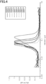
- Fig. 4 shows distribution curves of the pore volume Vp for the electrocatalyst layers of Reference Examples 1 to 3 and Comparative Examples 1 to 5.
- Fig. 5 shows a graph indicating relationships between cumulative pore volume ratio and pore size D, for the electrocatalyst layers of Reference Examples 1 to 3 and Comparative Examples 1 to 5.
- the pore size Dp at the peak of the distribution curve of the pore volume Vp was in the range of 0.06 ⁇ m or more and 0.1 ⁇ m or less.
- the percentage R(L) of the third integrated volume to the first integrated volume was in the range of 15% or more and 35% or less, and the percentage R(S) of the second integrated volume to the first integrated volume was in the range of 30% or more and 40% or less.
- the percentage of the integrated pore volume to the volume of the electrocatalyst layer was in the range of 65% or more and 90% or less.
- the gradient of the distribution curve indicating distribution of the cumulative pore volume with respect to the first pore size ( ⁇ m) range was in the range of 7 or more and 14 or less.
- the thickness of the electrocatalyst layer was in the range of 5 ⁇ m or more and 30 ⁇ m or less.
- power generation performance was evaluated as good and durability was also evaluated as good, regardless of the measurement conditions.
- the membrane electrode assemblies of Reference Examples 1 to 3 were capable of configuring fuel cells having good power generation performance and good durability.
- the pore size Dp at the peak of the distribution curve of the pore volume Vp was outside the range of 0.06 ⁇ m or more and 0.1 ⁇ m or less.
- the percentage R(L) of the third integrated volume to the first integrated volume was outside the range of 15% or more and 35% or less.
- the percentage R(S) of the second integrated volume to the first integrated volume was outside the range of 30% or more and 40% or less.
- Comparative Examples 3 and 5 the percentage of the integrated pore volume to the volume of the electrocatalyst layer was in the range of 65% or more and 90% or less, whereas in Comparative Examples 1, 2 and 4, the percentage of the pore volume to the volume of the electrocatalyst layer was 60%.
- the thickness of the electrocatalyst layer exceeded 30 ⁇ m, whereas in Comparative Examples 2 to 5, the thickness of the electrocatalyst layer was in the range of 5 ⁇ m or more and 30 ⁇ m or less.
- Comparative Examples 1 to 5 power generation performance was evaluated to be poor under the standard conditions and/or high humidity conditions. In Comparative Examples 2, 3 and 5, durability was also evaluated to be poor. Thus, according to Comparative Examples 1 to 5, power generation performance and/or durability were impaired, compared to the above reference examples.
- the advantageous effects enumerated below can be achieved.
- an electrocatalyst layer, a membrane electrode assembly, and a polymer electrolyte fuel cell according to a second aspect of the present disclosure will be described.
- the second aspect is different from the first aspect in the configuration of the electrocatalyst layer.
- the second aspect will be described focusing on the differences, omitting specific explanation of components common to the first aspect by designating the same reference signs thereto as those of the first aspect.
- an electrocatalyst layer and examples will be described in sequence.
- the electrocatalyst layer described below has a configuration that is applied to both the oxygen- and fuel-electrode-side electrocatalyst layers 12C and 12A, but may be applied to either of the oxygen- and fuel-electrode-side electrocatalyst layers 12C and 12A.
- each electrocatalyst layer 12 includes a catalytic material 21, an electrically conductive carrier 22, a polyelectrolyte 23 and a fibrous material 24, as in the electrocatalyst layer 12 of the first aspect.
- the catalytic material 21 is supported on the electrically conductive carrier 22.
- the portions containing no catalytic material 21, electrically conductive carrier 22, polyelectrolyte 23 and fibrous material 24 are voids.
- the catalyst carrier is configured by the electrically conductive carrier 22, and the catalytic material 21 which is supported on the electrically conductive carrier 22.
- voids having a diameter in the range of 3 nm or more and 5.5 ⁇ m or less, are defined to be pores.
- the diameter of a pore which is calculated from a pore volume Vp measured by mercury intrusion porosimetry is a pore size D.
- the pore size D is defined to be a size D of a cylindrical model pore acquired by mercury intrusion porosimetry.
- the pore size D is in the range of 3 nm or more and 5.5 ⁇ m or less.
- the maximum value of the pore volumes Vp of the electrocatalyst layer 12 is a maximum volume Vmax, and the pore size D for the pores having the maximum volume Vmax is a maximum-volume size Dmax.
- the pore volumes Vp of the electrocatalyst layer 12 are normalized (proportionally converted) by defining the minimum value of the pore volume Vp to be 0 and the maximum volume Vmax to be 1.
- the distribution of the pore volume Vp (pore volume distribution) with respect to the pore size D has a first peak top (Vmax, Dmax). Furthermore, in the second aspect of the present disclosure the pore volume distribution of the electrocatalyst layer 12 is required to satisfy the following Condition 6. When the pore volume distribution of the electrocatalyst layer 12 satisfies Condition 6, the electrocatalyst layer 12 will have voids exerting sufficient gas diffusion and drainage.
- Condition 6 is a preferred feature of the membrane electrode assembly according to the claimed invention.
- the pore volume distribution has a shoulder peak point (Di, Vi) in a region where the pore size is smaller than the maximum-volume size Dmax and where the pore volume Vp is 0.2 or more.
- Figs. 6 to 8 respectively show normalized distributions mentioned above.
- the horizontal axis represents pore size D and the vertical axis represents pore volume Vp.
- Fig. 6 shows a pore volume distribution of the electrocatalyst layer 12 without containing the fibrous material 24.
- Fig. 7 shows an example of a pore volume distribution of the electrocatalyst layer 12 according to the present aspect of the disclosure.
- Fig. 8 shows another example of a pore volume distribution of the electrocatalyst layer 12 according to the present aspect of the disclosure.
- the shoulder peak appears when two or more peaks of different sizes overlap in the pore volume distribution.
- the shoulder peak appears as part of the peak having a first peak top (Vmax, Dmax) as an apex.
- the peak top at the shoulder peak is a shoulder peak point (Vi, Di).
- an approximate curve of a first peak having a first peak top (Vmax, Dmax) as an apex is calculated first.
- a Gaussian function is used to approximate the first peak.
- a difference (Vp-Vp1) is calculated as a difference between a pore volume (first pore volume Vp1) at the pore size Dp in the approximate curve, and a pore volume Vp at the pore size Dp of the pore volume distribution.
- the pore size Dp when the difference (Vp-Vp1) is a maximum is specified to be a specific pore size Di, and the pore volume Vp then is specified to be a pore volume Vi.
- a shoulder peak point (Vi, Di) is specified.
- a difference (Vp-Vp1) of 0.01 or less which is a minor difference and is less likely to contribute to exerting the functions of the shoulder peak, is not used for specifying a shoulder peak point (Vi, Di).
- a shoulder peak point (Vi, Di) is specified at a shoulder peak which is the closest to the first peak top (Vmax, Dmax) among the multiple shoulder peaks.
- the first peak having a peak top (Vmax, Dmax) as an apex can be obtained such as by approximating the pore volume distribution with a Gaussian function or a Lorentz function. Since a Lorenz function tends to have a broader base than a Gaussian function, a Gaussian function is used in the present aspect of the disclosure.
- the maximum volume Vmax depends on the attributes of the fibrous material 24, such as the mixing ratio, diameter and length, or depends on the interaction between these attributes and the attributes of the catalyst carrier.
- the specific pore volume Vi depends on the attributes of the catalyst carrier, such as the mixing ratio and size, or depends on the interaction between these attributes and the attributes of the fibrous material 24.
- the fibrous material 24 and the catalyst carrier are combined so that the shoulder peak point (Di, Vi) derived from the attributes of the catalyst carrier and the first peak top (Vmax, Dmax) derived from the attributes of the fibrous material 24 satisfy the conditions described above.
- the shoulder peak point (Di, Vi) derived from the attributes of the catalyst carrier and the first peak top (Vmax, Dmax) derived from the attributes of the fibrous material 24 satisfy the conditions described above.
- the pore volume distribution may become a monotonic normal distribution having a peak point as an apex, and it may be difficult to achieve distribution of the pore size D, which is partially non-uniform.
- the specific pore volume Vi is larger than the maximum volume Vmax, the pore volume Vp of the specific pore size Di, which is smaller than the maximum-volume size Dmax, may occupy a large portion of the electrocatalyst layer 12, and sufficient gas diffusion and drainage may not be necessarily achieved.
- the specific pore volume Vi is preferred to be in the range of 0.3 or more and 0.8 or less, and more preferred to be 0.45 or more and 0.7 or less. If the shoulder peak point (Vi, Di) resides in these ranges, the pore volume distribution may be efficiently prevented from becoming a monotonic normal distribution.
- the specific pore size Di is in the range of 0.03 ⁇ m or more and 0.06 ⁇ m or less, and the maximum-volume size Dmax is in the range of 0.06 ⁇ m or more and 0.1 ⁇ m or less. If the specific pore volume Vi and the maximum volume Vmax are in the above ranges, regions where the pores are relatively sparse and large due to the fibrous material 24 may be balanced with regions where the pores are relatively dense and small due to the catalyst carrier, thereby enhancing gas diffusion and drainage.
- the difference (Dmax-Di) between the specific pore size Di and the maximum-volume size Dmax is preferred to be 0.02 ⁇ m or more.
- the difference (Dmax-Di) is 0.02 ⁇ m or more, the pore volume distribution may approximate to multimodality. Accordingly, sufficient gas diffusion and drainage may be easily achieved.
- the difference (Dmax-Di) is more than 0.07 ⁇ m, the porosity difference may increase. Accordingly, power generation performance may tend to be impaired under a low-humidity environment, although it may be satisfactory under a high-humidity environment.
- the difference (Vp-Vp1) between the pore volume Vp1 at the first peak (approximate curve) having a first peak top (Vmax, Dmax) as an apex and the pore volume Vp of the pore volume distribution is preferred to be 0.03 or more, and more preferred to be 0.06 or more, at the shoulder peak point (Vi, Di).
- the difference value (Vp-Vp1) is preferred to have an upper limit of 0.2 or less to balance regions where the pores are relatively sparse and large due to the fibrous material 24, with regions where the pores are relatively dense and small due to the catalyst carrier.
- the reaction expressed by the above Reaction Formula (1) occurs at the fuel electrode 30A of the polymer electrolyte fuel cell 30.
- the reaction expressed by the above Reaction Formula (2) occurs at the oxygen electrode 30C.
- the electrocatalyst layer 12 of the present aspect of the disclosure has high drainage performance by satisfying the conditions described above. Therefore, such an electrocatalyst layer 12 is preferred to be applied to the electrocatalyst layer 12 of the oxygen electrode 30C. In this way, the effect of enhancing power generation performance of the polymer electrolyte fuel cell 30 can be improved.
- the shoulder peak point (Vi, Di) may appear more easily.
- the shoulder peak may appear in a region where the pore size is larger than the maximum-volume size Dmax.
- the shoulder peak point (Vi, Di) may appear more easily.
- the mixing ratio of the fibrous material 24 is excessively high, the distribution may be broadened and the shoulder peak may not appear.
- the shoulder peak point (Vi, Di) may be shifted to a smaller pore size side.
- Platinum on carbon catalyst (TEC10E50E manufactured by Tanaka Kikinzoku Kogyo Co., Ltd.), water, 1-propanol, polyelectrolyte (Nafion (trademark) dispersion manufactured by Wako Pure Chemical Industries, Ltd.), and carbon nanofibers (VGCF (trademark)-H manufactured by Showa Denko K.K.) were mixed.
- a platinum catalyst is supported on carbon particles. The ratio of the mass of the carbon particles to the mass of the polyelectrolyte was 1:1. The mixture was then subjected to dispersion processing using a planetary ball mill at 300 rpm for 60 minutes.
- zirconia balls having a diameter of 5 mm were added to about one third of the zirconia container.
- a catalyst ink was thereby prepared.
- the catalyst ink was prepared so that the mass of the polyelectrolyte was 100 mass% relative to the mass of the carbon particles, the mass of the fibrous material was 100 mass% relative to the mass of the carbon particles, the proportion of water in the dispersion medium was 50 mass%, and the solid content of the catalyst ink was 10 mass%.
- the catalyst ink was applied to both surfaces of a polyelectrolyte membrane (Nafion (trademark) 211 manufactured by Dupont) by using a slit die coater to form a coating film.
- the catalyst ink was applied to the polyelectrolyte membrane so as to have a thickness of 150 ⁇ m on the cathode surface, and a thickness of 100 ⁇ m on the anode surface.
- the polyelectrolyte membrane provided with the coating films was then placed in a hot air oven heated to 80°C and dried until the tackiness of the coating films disappeared. In this way, a membrane electrode assembly of Reference Example 4 was obtained.
- a membrane electrode assembly of Reference Example 5 was obtained as in Reference Example 4, except that multiwall carbon nanotubes (60 nm to 100 nm in diameter, manufactured by Tokyo Chemical Industry Co., Ltd.) were used in place of carbon nanofibers.
- a membrane electrode assembly of Reference Example 6 was obtained as in Reference Example 4, except that the amount of carbon nanofibers was 1/2 of that of Reference Example 4 when preparing the catalyst ink.
- a catalyst ink was prepared as in Reference Example 4.
- the catalyst ink was applied to a surface of a PTFE film by using a slit die coater to form a coating film.
- the PTFE film was then placed in a hot air oven heated to 80°C and dried until the tackiness of the coating film disappeared. In this way, a substrate having a catalyst layer was obtained.
- a substrate having an oxygen-electrode-side electrocatalyst layer and a substrate having a fuel-electrode-side electrocatalyst layer were prepared.
- the catalyst ink was applied to a substrate (PTFE film) so as to have a thickness of 150 ⁇ m on the cathode surface, and a thickness of 60 ⁇ m on the anode surface.
- the substrates each having a catalyst layer were respectively disposed on the two surfaces of a polyelectrolyte membrane (Nafion (trademark) 211 manufactured by Dupont) to form a laminate.
- the laminate was hot-pressed at 120°C and 5 MPa to bond the two electrocatalyst layers to the polyelectrolyte membrane.
- the PTFE films were separated from the respective electrocatalyst layers to obtain a membrane electrode assembly of Reference Example 7.
- a membrane electrode assembly of Reference Example 8 was obtained as in Reference Example 4, except that the amount of carbon nanofibers was changed to 2 times of that of Reference Example 4 when preparing the catalyst ink.
- a membrane electrode assembly of Comparative Example 6 was obtained as in Reference Example 4, except that carbon nanotubes (NC7000 manufactured by Nanocyl SA) were used in place of carbon nanofibers.
- a membrane electrode assembly of Comparative Example 7 was obtained as in Reference Example 4, except that no carbon nanofibers were added when preparing the catalyst ink.
- a membrane electrode assembly of Comparative Example 8 was obtained as in Reference Example 4, except that the amount of carbon nanofibers was 1/10 of that of Example 4 when preparing the catalyst ink.
- Pore volume distribution was measured by mercury intrusion porosimetry. Specifically, the pore volume Vp was measured by using an automated porosimeter (Autopore IV9510 manufactured by Micromeritics) for a membrane electrode assembly in which only an oxygen-electrode-side electrocatalyst layer was formed on a polyelectrolyte membrane. The measured cell had a volume of approximately 5 cm 3 , and the pressure of mercury injection was increased stepwise from 3 kPa to 400 MPa. In this way, the injection amount of mercury, or pore volume Vp, at each pressure was obtained.
- Autopore IV9510 manufactured by Micromeritics
- Each pressure of mercury injection was converted to a pore size D by using Washburn's equation, and the pore volume Vp with respect to the pore size D was plotted as a distribution function dVp/dlogD.
- the surface tension ⁇ was taken to be 0.48 N/m, and the contact angle ⁇ was taken to be 130°. This plot was a pore volume distribution, which was normalized.
- a maximum volume Vmax and a maximum-volume size Dmax were detected from the normalized pore volume distribution.
- the maximum volume Vmax was 1 because the pore volumes distribution had been normalized.
- a specific pore volume Vi, a specific pore size Di, and a specific difference (Vp-Vp1) were detected by using the pore volume distribution.
- a cross section of the electrocatalyst layer was observed by using a scanning electron microscope (SEM) to measure the thickness of the electrocatalyst layer. Specifically, a cross section of the electrocatalyst layer was observed at 1,000 times magnification by using a scanning electron microscope (FE-SEM S-4800 manufactured by Hitachi High-Technologies, Ltd., currently Hitachi High-Tech Corporation). The thickness of the electrocatalyst layer was measured at 30 observation points of the cross section. The average of the thicknesses at the 30 observation points was defined to be the thickness of the electrocatalyst layer.
- SEM scanning electron microscope
- Power generation performance was measured by using a method according to a booklet titled "Cell unit evaluation and analysis protocol” and published by the New Energy and Industrial Technology Development Organization (NEDO).
- a JARI standard cell was used as a cell unit for evaluation.
- a gas diffusion layer, a gasket, and a separator were disposed on each surface of a membrane electrode assembly and pressed against the surface to achieve a predetermined surface pressure.
- IV measurements were performed according to the method described in the booklet "Cell unit evaluation and analysis protocol". These conditions were defined to be standard conditions. Also, IV measurements were performed with the relative humidities of the anode and cathode both being set to RH 100%. These conditions were defined to be high humidity conditions.
- Table 2 shows measurements for the fuel cells respectively including the membrane electrode assemblies of Reference Examples 4 to 8 and Comparative Examples 6 to 8, as well as power generation performance and durability of these assemblies.
- cell units having a current of 25 A or more at a voltage of 0.6 V were evaluated as good, and cell units having a current of less than 25 A at a voltage of 0.6 V were evaluated as poor.
- cell units having a current of 30 A or more at a voltage of 0.6V were evaluated as good, and cell units having a current of less than 30 A at a voltage of 0.6 V were evaluated as poor.
- cell units having a hydrogen cross leak current of less than 10 times of the initial value after the lapse of 8,000 cycles were evaluated as good, and cell units having a hydrogen cross leak current of 10 times or more of the initial value after the lapse of 8,000 cycles were evaluated as poor.
- the pore volume distribution had a shoulder peak point (Di, Vi) satisfying the required conditions in a region where the pore size was smaller than the maximum-volume size Dmax and where the pore volume Vp was 0.2 or more. Furthermore, power generation performance and durability under the high humidity conditions were good. In Reference Examples 4 to 8, membrane electrode assemblies that could configure fuel cells having good power generation performance and durability under the high humidity conditions were obtained.
- Comparative Examples 6 to 8 had a pore volume distribution with a shoulder peak point (Vi, Di) in a region where the pore size was smaller than the maximum-volume size Dmax and where the pore volume Vp was 0.2 or more. Furthermore, power generation performance under the high humidity conditions was poor.
- the electrocatalyst layer 12 contains voids for achieving sufficient gas diffusion and drainage, whereby power generation performance can be enhanced under the high humidity conditions.
- the electrocatalyst layer 12 of the second aspect of the present disclosure can be combined with the configuration of the electrocatalyst layer 12 of the first aspect. Specifically, the electrocatalyst layer 12 of the second aspect of the present disclosure may satisfy at least one of Conditions (1) to (5) in addition to Condition (6) set forth above.
- a claimed embodiment of a membrane electrode assembly and a polymer electrolyte fuel cell according to the present invention will be described.
- the claimed embodiment is different from the first aspect of the present disclosure in the configuration of the membrane electrode assembly.
- the claimed embodiment will be described focusing on the differences, omitting specific explanation of components common to the first aspect of the disclosure by designating the same reference signs thereto as those of the first aspect of the disclosure.
- the oxygen-electrode-side electrocatalyst layer 12C contains a fibrous material 24, but the fuel-electrode-side electrocatalyst layer 12A may or may not contain the fibrous material 24.
- the fuel-electrode-side electrocatalyst layer 12A contains a first catalytic material, a first electrically conductive carrier, and a first polyelectrolyte.
- the oxygen-electrode-side electrocatalyst layer 12C contains a second catalytic material, a second conductive carrier, a second polyelectrolyte, and a fibrous material.
- the first catalytic material may be the same as or different from the second catalytic material.
- the first electrically conductive carrier may be the same as or different from the second electrically conductive carrier.
- the first catalytic material may be the same as or different from the second catalytic material.
- the portions containing no catalytic material 21, electrically conductive carrier 22, polyelectrolyte 23 and fibrous material 24 are voids.
- voids having a diameter in the range of 3 nm or more and 5.5 ⁇ m or less are defined to be pores.
- the membrane electrode assembly 10 includes voids, and the voids include pores each having a size in the range of 3 nm or more and 5.5 ⁇ m or less.
- pore volumes Vp of pores having a specific pore size D are measured and calculated by mercury intrusion porosimetry.
- the pore size D is defined to be a size D of a cylindrical model pore acquired by mercury intrusion porosimetry.
- the pore volumes Vp correspond to a sum of volumes of the pores having a specific pore size D among the pores.
- a predetermined pressure P is required to be applied thereto for entry into pores.
- Distribution of the pore volume Vp or a specific surface area can be calculated from a pressure P applied to the mercury to enter the pores, and the amount of mercury injected into the pores.
- the relationship between the applied pressure P and the pore size D enabling mercury to enter therein with the pressure P can be expressed by Formula (1) which is known as Washburn's equation.
- ⁇ is the surface tension of mercury
- ⁇ is the contact angle between mercury and the wall surface of a pore.
- a pore size D is calculated assuming the surface tension ⁇ to be 0.48 N/m and the contact angle ⁇ to be 130 ° .
- D ⁇ 4 ⁇ cos ⁇ / P
- the volume of injected mercury is recorded every time a different pressure P is applied. Then, each pressure P is converted to a pore size D based on Formula (1). Assuming that the volume of the injected mercury is equal to the pore volume Vp, a pore volume increase dV is plotted against the pore size D.
- the pore volume increase dV in this case is an increase of the pore volume Vp when the pore size has increased from D to D+dD.
- the peak of the plot is the peak of the distribution of the pore volume Vp.
- Functions required for enhancing power generation performance in the membrane electrode assembly 10 are, for example, maintaining a three-phase interface in the electrocatalyst layer 12 included in the membrane electrode assembly 10, diffusing gas in the electrocatalyst layer 12, and draining water produced in the electrocatalyst layer 12.
- the pore size D suitable for maintaining the three-phase interface, the pore size D suitable for diffusing gas, and the pore size D suitable for draining produced water are different from each other.
- the pore size D suitable for maintaining the three-phase interface, the pore size D suitable for diffusing gas, and the pore size D suitable for draining produced water do not have to be necessarily the same, but may include ranges different from each other.
- the pore sizes D suitable for gas diffusion in the oxygen- and fuel-electrode-side electrocatalyst layers 12C and 12A are also different from each other.
- the pore size D suitable for enhancing power generation performance is required to satisfy these pore sizes D.
- the three-phase interface refers to an interface formed by a polyelectrolyte, a catalyst and a gas.
- the membrane electrode assembly 10 according to the present invention is required to satisfy the following Condition 7.
- the pore size D at the peak of the distribution curve indicating distribution of the pore volume Vp with respect to the pore size D is in the range of 0.06 or more and 0.11 ⁇ m or less (0.06 ⁇ m ⁇ D ⁇ 0.11 ⁇ m). If the pore size D at the peak of the distribution curve is in the range of 0.06 ⁇ m or more and 0.11 ⁇ m or less, the electrocatalyst layer 12 can contain voids for achieving sufficient gas diffusion and drainage.
- Fig. 9 shows an example of distribution curves each indicating distribution of the pore volume Vp with respect to the pore size D.
- the pore sizes D at the peaks of the distribution curves B and C are in the range of 0.06 or more and 0.11 ⁇ m or less.
- the pore sizes D at the peaks of the distribution curves A and D are outside the range of 0.06 ⁇ m or more and 0.11 ⁇ m or less. More specifically, the pore size D at the peak of the distribution curve A is less than 0.06 ⁇ m. In contrast, the pore size D at the peak of the distribution curve D is more than 0.11 ⁇ m.
- Condition 8 Given that the membrane electrode assembly 10 according to the present invention satisfies Condition 7, the following Condition 8 is also preferred to be satisfied.
- the full width at half maximum in the distribution curve indicating distribution of the pore volume Vp with respect to the pore size D is preferred to be in the range of 0.13 ⁇ m or more and 0.18 ⁇ m or less.
- the full width at half maximum is more preferred-to be in the range 0.14 ⁇ m or more and 0.17 ⁇ m or less.
- minimum and maximum pore sizes D satisfying f(Dmax)/2 are respectively defined to be a minimum size D1 and a maximum size D2.
- a difference (D2-D1) obtained by subtracting the minimum size D1 from the maximum size D2 is defined to be a full width at half maximum.
- Reaction in the polymer electrolyte fuel cell 30 is expressed by the above Reaction Formulas (1) and (2) set forth above. Specifically, fuel gas and oxidant gas of a predetermined ratio are required to be fed into the membrane electrode assembly 10 to promote reaction in the polymer electrolyte fuel cell 30.
- the distribution curve of the pore volume Vp may have multimodality.
- Fig. 10 shows a distribution curve of the pore volume Vp having bimodality, which is an example of multimodality. It is difficult to achieve bimodality in the distribution curve of the pore volume Vp by only the oxygen-electrode-side electrocatalyst layer 12C or the fuel-electrode-side electrocatalyst layer 12A. Therefore, if distribution of the pore volume Vp has bimodality, distribution of the pore volume Vp may be different between the oxygen- and fuel-electrode-side electrocatalyst layers 12C and 12A.
- the distribution curve of the pore volume Vp of the membrane electrode assembly 10 may have bimodality.
- the distribution of the pore size D may also be unbalanced between the oxygen- and fuel-electrode-side electrocatalyst layers 12C and 12A.
- the distribution curve of the pore volume Vp may accordingly have a near unimodal shape.
- the range of distribution of the pore size D in each electrocatalyst layer 12 may be excessively wide. If the full width at half maximum of the distribution curve is less than 0.13 ⁇ m, the range of distribution of the pore size D in each electrocatalyst layer 12 may be excessively narrow. Therefore, power generation performance of the polymer electrolyte fuel cell 30 may be impaired for the same reasons as in the bimodal case. In other words, if the full width at half maximum is 0.18 ⁇ m or less, the range of distribution of the pore size D may be prevented from becoming excessively wide.
- the range of distribution of the pore size D may be prevented from becoming excessively narrow. In this way, when the full width at half maximum is in the range of 0.13 ⁇ m or more and 0.18 ⁇ m or less, distribution of the pore size D can be in a suitable range. Thus, power generation performance of the polymer electrolyte fuel cell 30 including the membrane electrode assembly 10 can be enhanced.
- the membrane electrode assembly 10 according to the present invention may additionally satisfy one of the following Conditions 9 to 11.
- the value obtained by integrating the pore volumes Vp of pores having a pore size D in the entire range is a first integrated volume ( ⁇ Vp 1).
- the value obtained by integrating the pore volumes Vp of pores having a pore size D of 50 nm or less is a second integrated volume ( ⁇ Vp 2).
- the percentage of the second integrated volume to the first integrated volume is in the range of 25% or more and 45% or less.
- the value obtained by integrating the pore volumes Vp of pores having a pore size D of 100 nm or more is a third integrated volume ( ⁇ Vp 3).
- the percentage of the third integrated volume to the first integrated volume is in the range of 30% or more and 50% or less.
- the pores of the membrane electrode assembly 10 include pores having a relatively large size in the above ratio, the three-phase interface can be maintained in the electrocatalyst layer 12 of the membrane electrode assembly 10, and gas diffusion and drainage of the produced water can be enhanced in the electrocatalyst layer 12. If the pores of the electrocatalyst layer 12 include pores having a relatively small size within the above range, the three-phase interface can be maintained in the electrocatalyst layer 12, and gas diffusion and drainage of the produced water can be enhanced in the electrocatalyst layer 12.
- the value obtained by integrating the pore volumes Vp of the pores having a pore size in the entire range is a first log differential integrated volume ( ⁇ (dVp/d(logD)) 1).
- the value obtained by integrating the pore volumes of pores having a pore size D of 60 nm or less is a second log-differential integrated volume ( ⁇ (dVp/d(logD)) 2).
- the percentage of the second log differential integrated volume to the first log differential integrated volume ( ⁇ (dVp/d(logD)) 2 / ⁇ (dVp/d(logD)) 1 ⁇ 100) is in the range of 30% or more and 60% or less.
- the value obtained by integrating the pore volumes Vp of pores having a pore size D of 100 nm or more is a third log differential integrated volume ( ⁇ (dVp/d(logD)) 3).
- the percentage of the third log differential integrated volume to the first log differential integrated volume ( ⁇ (dVp/d(logD)) 3 / ⁇ (dVp/d(logD)) 1 ⁇ 100) is in the range of 30% or more and 60% or less.
- the membrane electrode assembly 10 may contain pores having a relatively large size in the ratio mentioned above and pores having a relatively small size in the ratio mentioned above. Therefore, the three-phase interface can be maintained in the electrocatalyst layer 12 of the membrane electrode assembly 10, and gas diffusion and drainage of the produced water can be enhanced in the electrocatalyst layer 12.
- the ratio of the second log differential integrated volume to the third log differential integrated volume in Condition 11 is in the range of 0.7 or more and 1.5 or less. If Condition 12 is satisfied, the ratio of the relatively small pores to the relatively large pores may be in the range which is suitable for maintaining the three-phase interface and enhancing gas diffusion and drainage of the produced water. This may further enhance power generation performance of the polymer electrolyte fuel cell 30 to which the membrane electrode assembly 10 is applied.
- the mass of the fibrous material 24 per unit volume of the fuel-electrode-side electrocatalyst layer 12A is preferred to be greater than the content of the fibrous material 24 per unit volume of the oxygen-electrode-side electrocatalyst layer 12C. If the mass of the fibrous material 24 per unit volume of the fuel-pole-side electrocatalyst layer 12A is large, the fuel-electrode-side electrocatalyst layer 12A is more likely to contain pores having a larger pore size D than is the oxygen-electrode-side electrocatalyst layer 12C. In this way, the fuel gas may more efficiently flow into the membrane electrode assembly 10.
- the fibrous material 24 may be the same or may be different between the oxygen- and fuel-electrode-side electrocatalyst layers 12C and 12A
- a cross section of the membrane electrode assembly 10 By observing a cross section of the membrane electrode assembly 10 by using a scanning electron microscope (SEM), the content of the fibrous material 24 can be compared between the oxygen- and fuel-electrode-side electrocatalyst layers 12C and 12A.
- a cross section of the membrane electrode assembly 10 may be observed at 1,000 times magnification by using a scanning electron microscope (FE-SEM S-4800 manufactured by Hitachi High-Technologies, Ltd., currently Hitachi High-Tech Corporation) to randomly extract 30 observation points from each of the oxygen- and fuel-electrode-side electrocatalyst layers 12C and 12A.
- FE-SEM S-4800 manufactured by Hitachi High-Technologies, Ltd., currently Hitachi High-Tech Corporation
- individual observation points may be randomly extracted from the 30 observation points of each of the electrocatalyst layers 12 to sequentially compare the extracted observation points between the oxygen- and fuel-electrode-side electrocatalyst layers 12C and 12A.
- the extracted observation points may be visually observed and the content of the fibrous material 24 may be compared between the oxygen- and fuel-electrode-side electrocatalyst layers 12C and 12A to determine which is larger.
- the content of the fibrous material 24, as to which is higher or lower can be determined by majority.
- the content of the fibrous material 24 in the fuel-electrode-side electrocatalyst layer 12A may be determined to be higher than the content of the fibrous material 24 in the oxygen-electrode-side electrocatalyst layer 12C at the majority of observation points.
- the mass of the fibrous material 24 per unit volume in the fuel-electrode-side electrocatalyst layer 12A can be determined to be greater than the mass of the fibrous material 24 per unit volume in the oxygen-electrode-side electrocatalyst layer 12C.
- the percentage (V/V 0 ⁇ 100(%)) of the integrated volume V obtained by integrating the pore volumes of all the pores in the electrocatalyst layer 12 to the geometric volume V 0 of the electrocatalyst layer 12 is in the range of 60% or more and 80% or less. This allows the electrocatalyst layer 12 to provide better gas diffusion and drainage.
- the geometric volume V 0 of the electrocatalyst layer 12 is obtained by subtracting the product of the area and thickness of the polyelectrolyte membrane 11 from the product of the area and thickness of the membrane electrode assembly 10 used for the measurements based on mercury intrusion porosimetry.
- the oxygen-electrode-side electrocatalyst layer 12C is preferred to have a thickness in the range of 5 ⁇ m or more and 30 ⁇ m or less. If the oxygen-electrode-side electrocatalyst layer 12C has a thickness of 30 ⁇ m or less, the occurrence of cracking may be minimized in the oxygen-electrode-side electrocatalyst layer 12C.
- Use of the oxygen-electrode-side electrocatalyst layer 12C for a polymer electrolyte fuel cell 30 may prevent diffusion of the gas or produced water and electrical conductivity from being impaired, and further, may prevent the output of the polymer electrolyte fuel cell 30 from being lowered.
- the oxygen-electrode-side electrocatalyst layer 12C if it has a thickness of 5 ⁇ m or more, may be less likely to suffer thickness variation, and accordingly the catalytic material 21 or the polyelectrolyte 23 contained therein may be prevented from being non-uniformly distributed. Cracking on the surface of the oxygen-electrode-side electrocatalyst layer 12C or uneven thickness thereof are undesirable because they are very likely to adversely affect durability of the polymer electrolyte fuel cell 30 if the oxygen-electrode-side electrocatalyst layer 12C is used as part thereof and if the polymer electrolyte fuel cell 30 is operated for a long period of time.
- the fuel-electrode-side electrocatalyst layer 12A is preferred to have a thickness in the range of 5 ⁇ m or more and 20 ⁇ m or less. If the thickness of the fuel-electrode-side electrocatalyst layer 12A is 20 ⁇ m or less, the occurrence of cracking may be minimized. Use of the fuel-electrode-side electrocatalyst layer 12A for the polymer electrolyte fuel cell 30 may prevent gas diffusion or electrical conductivity from being impaired, and further, may prevent the output of the polymer electrolyte fuel cell 30 from being lowered.
- the fuel-electrode-side electrocatalyst layer 12A if it has a thickness of 5 ⁇ m or more, may be less likely to suffer thickness variation, and accordingly the catalytic material 21 or the polyelectrolyte 23 contained therein is prevented from being non-uniformly distributed. Cracking on the surface of the fuel-electrode-side electrocatalyst layer 12A or uneven thickness thereof are undesirable because they are very likely to adversely affect durability of the polymer electrolyte fuel cell 30 if the fuel-electrode-side electrocatalyst layer 12A is used as part thereof and if the polymer electrolyte fuel cell 30 is operated for a long period of time.
- the size and distribution of the pores of the electrocatalyst layers 12 can be controlled by controlling the temperature of heating the catalyst ink coating film, the rate of heating the coating film, the pressing conditions under which the catalyst ink is dried, the mixing ratio of the fibrous material 24, the mixing ratio of the polyelectrolyte 23, the solvent composition of the catalyst ink, the dispersion strength when controlling the catalyst ink, and the like.
- the mixing ratio of the fibrous material 24 is increased, the pore size D corresponding to the peak of the distribution curve is increased accordingly, and as the mixing ratio of the polyelectrolyte 23 is decreased, the pore volume is increased accordingly.
- Platinum on carbon catalyst (TEC10E50E manufactured by Tanaka Kikinzoku Kogyo Co., Ltd.), water, 1-propanol, polyelectrolyte (Nafion (trademark) dispersion manufactured by Wako Pure Chemical Industries, Ltd.), and carbon nanofibers (VGCF (trademark)-H manufactured by Showa Denko K.K.) were mixed.
- a platinum catalyst is supported on carbon particles.
- the mixture was then subjected to dispersion processing using a planetary ball mill at 300 rpm for 60 minutes. In this case, zirconia balls having a diameter of 5 mm were added to about one third of the zirconia container.
- a catalyst ink for the oxygen electrode was prepared so that the mass of the polyelectrolyte was 100 mass% relative to the mass of the carbon particles, the mass of the carbon nanofibers was 100 mass% relative to the mass of the carbon particles, the proportion of water in the dispersion medium was 50 mass%, and the solid content was 10 mass%.
- a catalyst ink for the fuel electrode was prepared using the same method as that used for the catalyst ink for the oxygen electrode, except that the mass of the carbon nanofibers was 150 mass% relative the mass of carbon particles.
- the catalyst ink for the oxygen electrode was applied to one surface of a polyelectrolyte membrane (Nafion (trademark) 211 manufactured by Dupont) by using a slit die coater to form a coating film having a thickness of 150 ⁇ m.
- the polyelectrolyte membrane provided with the coating film on one surface was then placed in a hot air oven heated to 80°C and dried until the tackiness of the coating film disappeared to form an oxygen-electrode-side electrocatalyst layer.
- the catalyst ink for the fuel electrode was applied to the other surface of the polyelectrolyte membrane by using a slit die coater to form a coating film having a thickness of 50 ⁇ m.
- Example 9 The polyelectrolyte membrane provided with the coating film on the other surface was then placed in a hot air oven heated to 80°C and dried until the tackiness of the coating film disappeared to form a fuel-electrode-side electrocatalyst layer. In this way, a membrane electrode assembly of Example 9 was obtained.
- a membrane electrode assembly of Example 10 was obtained as in Example 9, except that multiwall carbon nanotubes (60 nm to 100 nm in diameter manufactured by Tokyo Chemical Industry Co., Ltd.) were used in place of carbon nanofibers (VGCF (trademark)-H manufactured by Showa Denko K.K.) when preparing the catalyst ink.
- VGCF carbon nanofibers
- a membrane electrode assembly of Example 11 was obtained as in Example 9, except that the amount of carbon nanofibers was 1/2 of that of Example 9 when preparing the catalyst ink for the oxygen electrode.
- a membrane electrode assembly of Example 12 was obtained as in Example 9, except that the amount of carbon nanofibers was 1/5 of that of Example 9 when preparing the catalyst ink for the oxygen electrode.
- a membrane electrode assembly of Example 13 was obtained as in Example 9, except that the amount of polyelectrolyte was 1/2 of that of Example 9 when preparing the catalyst ink for the oxygen electrode.
- Catalyst inks were prepared as in Example 9.
- the catalyst ink for the oxygen electrode was applied to a surface of a PTFE film by using a slit die coater to form a coating film having a thickness of 150 ⁇ m.
- the PTFE film provided with the coating film was then placed in a hot air oven heated to 80°C and dried until the tackiness of the coating film disappeared to form a transfer substrate having an oxygen-electrode-side electrocatalyst layer.
- the catalyst ink for the fuel electrode was applied to a surface of another PTFE film by using a slit die coater to form a coating film having a thickness of 50 ⁇ m.
- the PTFE film provided with the coating film was then placed in a hot air oven heated to 80°C and dried until the tackiness of the coating film disappeared to form a transfer substrate having a fuel-electrode-side electrocatalyst layer.
- the transfer substrate having an oxygen-electrode-side electrocatalyst layer was placed on one surface of a polyelectrolyte membrane (Nafion (trademark) 211 manufactured by Dupont), and the transfer substrate having a fuel-electrode-side electrocatalyst layer was placed on the other surface of the polyelectrolyte membrane to form a laminate.
- the laminate was hot-pressed at a temperature of 120°C and a pressure of 1 MPa. In this way, the two electrocatalyst layers were bonded to the polyelectrolyte membrane. Then, the PTFE films were removed from the respective electrocatalyst layers to obtain a membrane electrode assembly of Example 14.
- a membrane electrode assembly of Comparative Example 9 was obtained as in Example 9, except that the amount of carbon nanofibers was 2 times of that of Example 9 when preparing the catalyst ink for the oxygen electrode.
- a membrane electrode assembly of Comparative Example 10 was obtained as in Example 9, except that the amount of polyelectrolyte was 2 times of that of Example 9 when preparing the catalyst ink for the oxygen electrode.
- a membrane electrode assembly of Comparative Example 11 was obtained as in Example 9, except that carbon nanotubes (NC7000 manufactured by Nanocyl SA) were used in place of carbon nanofibers (VGCF (trademark)-H manufactured by Showa Denko K.K.) when preparing the catalyst ink for the oxygen electrode.
- NC7000 manufactured by Nanocyl SA carbon nanotubes
- VGCF carbon nanofibers
- a membrane electrode assembly of Comparative Example 12 was obtained as in Example 12, except that the amount of carbon nanofibers was 2 times of that of Example 12 when preparing the catalyst ink for the fuel electrode.
- a membrane electrode assembly of Comparative Example 13 was obtained as in Example 9, except that no carbon nanofibers were added when preparing individual catalyst inks.
- Distribution of the pore volume Vp was measured by mercury intrusion porosimetry. Specifically, a membrane electrode assembly having a size of about 25 cm 2 was prepared, and the pore volume Vp was measured by using an automated porosimeter (Autopore IV9510 manufactured by Micromeritix). The measured cell had a volume of approximately 5 cm 3 , and the pressure of mercury injection was increased stepwise from 3 kPa to 400 MPa. In this way, the injection amount of mercury, or pore volume Vp, at each pressure was obtained. The pressure of mercury injection was converted to a pore size D by using Washburn's equation, and a pore volume Vp with respect to the pore size D was plotted as a distribution function dVp/dlogD (log differential pore volume distribution). The surface tension y was taken to be 0.48 N/m, and the contact angle ⁇ was taken to be 130°. The pore size D corresponding to the peak of the plot was read out as a pore size Dp.
- an automated porosimeter Autopore IV95
- the volumes of all the pores having a pore size in the range of 3 nm or more and 5.5 ⁇ m or less were integrated to calculate a first log differential integrated volume.
- a second log differential integrated volume was calculated by integrating the volumes of the pores having a pore size D of 60 nm or less
- a third log differential integrated volume was calculated by integrating the volumes of the pores having a pore size D of 100 nm or more.
- the second log differential integrated volume was divided by the first log differential integrated volume, and the quotient was multiplied by 100 to calculate a percentage (%) of the second log differential integrated volume to the first log differential integrated volume.
- the third log differential integrated volume was divided by the first log differential integrated volume, and the quotient was multiplied by 100 to calculate a percentage (%) of the third log differential integrated volume to the first log differential integrated volume.
- the second log differential integrated volume was divided by the third log differential integrated volume, and the quotient was multiplied by 100 to calculate a percentage (%) of the second log differential integrated volume to the third log differential integrated volume.
- a second integrated volume was calculated by integrating the volumes of the pores having a pore volume of 50 nm or less, and a third integrated volume was calculated by integrating the volumes of the pores having a pore volume of 100 nm or more.
- the second integrated volume was divided by the first integrated volume, and the quotient was multiplied by 100 to calculate a percentage (%) of the second integrated volume to the first integrated volume.
- the third integrated volume was divided by the first integrated volume, and the quotient was multiplied by 100 to calculate a percentage (%) of the third integrated volume to the first integrated volume.
- the area of the membrane electrode assembly subjected to measurements by use of the automated porosimeter and the thickness of the polyelectrolyte membrane were multiplied together to calculate a volume of the polyelectrolyte membrane.
- the volume of the polyelectrolyte membrane was subtracted from the volume of the membrane electrode assembly to calculate a geometric volume V 0 of the electrocatalyst layers.
- a percentage of the integrated pore volume V to the geometric volume V 0 of the electrocatalyst layers (V/V 0 ) was calculated.
- a cross section of the membrane electrode assembly was observed using a scanning electron microscope (SEM) to measure the thicknesses of the membrane electrode assembly, the cathode-side electrocatalyst layer, the anode-side electrocatalyst layer, and the polyelectrolyte membrane.
- SEM scanning electron microscope
- a cross section of the membrane electrode assembly was observed at 1,000 times magnification by using a scanning electron microscope (FE-SEM S-4800 manufactured by Hitachi High-Technologies, Ltd., currently Hitachi High-Tech Corporation).
- the thicknesses of the electrocatalyst layers were measured at 30 observation points of the cross section. The average thickness at the 30 observation points was defined to be the thickness of each layer.
- Power generation performance was measured by using a method according to a booklet titled "Cell unit evaluation and analysis protocol” and published by the New Energy and Industrial Technology Development Organization (NEDO).
- a JARI standard cell was used as a cell unit for evaluation.
- a gas diffusion layer, a gasket, and a separator were disposed on each surface of a membrane electrode assembly and pressed against the surface to achieve a predetermined surface pressure.
- IV measurements were performed according to the method described in the booklet "Cell unit evaluation and analysis protocol". These conditions were defined to be standard conditions. Also, IV measurements were performed with the relative humidities of the anode and cathode both being set to RH 100%. These conditions were defined to be high humidity conditions.
- Table 3 shows results on the following items for the membrane electrode assemblies of Examples 9 to 14 and Comparative Examples 9 to 13.
- Table 3 shows pore size Dp at the peak of the distribution curve of the pore volume Vp, percentage V/V 0 (%) of integrated pore volume V to volume V 0 of the electrocatalyst layers of the membrane electrode assembly, and thickness T ( ⁇ m) of the electrocatalyst layer, for the individual membrane electrode assemblies.
- Table 3 shows measurements of power generation performance and durability on the polymer electrolyte fuel cells respectively including membrane electrode assemblies of Examples 9 to 14 and Comparative Examples 9 to 13.
- the cell units having a current of 25 A or more at a voltage of 0.6 V were evaluated as good, and cell units having a current of less than 25 A at a voltage of 0.6 V were evaluated as poor.
- cell units having a current of 30 A or more at a voltage of 0.6V were evaluated as good, and cell units having a current of less than 30 A at a voltage of 0.6 V were evaluated as poor.
- cell units having a hydrogen cross leak current of less than 10 times of the initial value after the lapse of 10,000 cycles were evaluated as good, and cell units having a hydrogen cross leak current of 10 times or more of the initial value after the lapse of 10,000 cycles were evaluated as poor.
- Fig. 12 shows distribution curves of the pore volume Vp, for membrane electrode assemblies of Examples 9 and 10 and Comparative Examples 9 and 13.
- the region defining a range of the pore size being 60 nm or less is indicated by first dots
- the region defining a range of the pore size being 100 nm or more is indicated by second dots.
- Fig. 13 shows a graph indicating relationships between cumulative pore volume ratio and pore size D, for membrane electrode assemblies of Examples 9 and 10 and Comparative Examples 9 and 13.
- the pore size Dp at the peak of the distribution curve of the pore volume Vp was in the range of 0.06 ⁇ m or more and 0.1 ⁇ m or less.
- the percentage V/V 0 of the integrated pore volume V to the geometric volume V 0 of the electrocatalyst layers of the membrane electrode assembly was in the range of 60% or more and 80% or less.
- Example 9 the full widths at half maximum were 0.164 ⁇ m and 0.146 ⁇ m, respectively.
- the percentage of the second integrated volume to the first integrated volume was 33%, and the percentage of the third integrated volume to the first integrated volume was 42%.
- the percentage of the second integrated volume to the first integrated volume was 35%, and the percentage of the third integrated volume to the first integrated volume was 40%.
- Example 9 the first, second and third log differential integrated volumes were respectively 15.8, 6.0 and 5.9. Specifically, in Example 9, the percentage of the second log differential integrated volume to the first log differential integrated volume was 37.7%, and the percentage of the third log differential integrated volume to the first log differential integrated volume was 37.3%. In Example 9, the ratio of the second log differential integrated volume to the third log differential integrated volume was 1.0.
- Example 10 the first, second and third log differential integrated volumes were respectively 16.9, 6.6 and 6.0. Specifically, in Example 10, the percentage of the second log differential integrated volume to the first log differential integrated volume was 39.1%, and the percentage of the third log differential integrated volume to the first log differential integrated volume was 35.4%. In Example 10, the ratio of the second log differential integrated volume to the third log differential integrated volume was 1.1.
- Example 9 to 14 power generation performance was evaluated as good and durability was also evaluated as good, regardless of the measurement conditions. Specifically, the membrane electrode assemblies of Examples 9 to 14 were capable of forming a polymer electrolyte fuel cell having good power generation performance and good durability.
- the pore size Dp at the peak of the distribution curve of the pore volume Vp was outside the range of 0.06 ⁇ m or more and 0.11 ⁇ m or less.
- the percentage V/V 0 of the integrated pore volume V to the geometric volume V 0 of the electrocatalyst layers of the membrane electrode assembly was outside the range of 60% or more and 80% or less.
- Comparative Examples 13 and 9 the full widths at half maximum were 0.026 ⁇ m and 0.196, respectively.
- the percentage of the second integrated volume to the first integrated volume was 22%, and the percentage of the third integrated volume to the first integrated volume was 57%.
- the percentage of the second integrated volume to the first integrated volume was 70%, and the percentage of the third integrated volume to the first integrated volume was 8%.
- Comparative Example 9 the first, second and third log differential integrated volumes were respectively 17.3, 4.9 and 9.8. Specifically, in Comparative Example 9, the percentage of the second log differential integrated volume to the first log differential integrated volume was 26.7%, and the percentage of the third log differential integrated volume to the first log differential integrated volume was 56.9%. In Comparative Example 9, the ratio of the second log differential integrated volume to the third log differential integrated volume was 0.5.
- the first, second and third log differential integrated volumes were respectively 13.1, 10.9 and 0.9. Specifically, the percentage of the second log differential integrated volume to the first log differential integrated volume was 81.1%, and the percentage of the third log differential integrated volume to the first log differential integrated volume was 6.8%. In Comparative Example 13, the ratio of the second log differential integrated volume to the third log differential integrated volume was 11.8.
- Comparative Examples 9 to 13 power generation performance was evaluated to be poor under the standard conditions and/or high humidity conditions. In Comparative Examples 10, 12 and 13, durability was also evaluated to be poor. Thus, according to Comparative Examples 9 to 13, power generation performance and/or durability were impaired, compared to the above examples.
- the electrocatalyst layer 12 contains voids for achieving sufficient gas diffusion and drainage. In this way, power generation performance of the polymer electrolyte fuel cell 30 including the membrane electrode assembly 10 can be enhanced.
- the distribution range of the pore size D can be an appropriate range.
- the pores can include those pores which have a relatively small size in the above range, so that the three-phase interface can be maintained in the electrocatalyst layers 12, and gas diffusion and drainage of the produced water can be enhanced in the electrocatalyst layers 12.
- the pores can include those pores which have relatively large sizes in the above range, so that the three-phase interface can be maintained in the electrocatalyst layers 12, and gas diffusion and drainage of the produced water can be enhanced in the electrocatalyst layers 12.
- the pores can include those pores which have relatively large sizes and relatively small sizes in this range. In this way, the three-phase interface can be maintained in the electrocatalyst layers 12, and gas diffusion and drainage of the produced water can be enhanced in the electrocatalyst layers 12.
- the ratio of the second log-differential integrated volume to the third log-differential integrated volume is in the range of 0.7 or more and 1.5 or less
- the ratio of the relatively small pores to the relatively large pores can be in a range which is suitable for maintaining the three-phase interface and enhancing gas diffusion and drainage of the produced water. This may further enhance power generation performance of the polymer electrolyte fuel cell 30 to which the membrane electrode assembly 10 is applied.
- the percentage V/V 0 of the integrated pore volume to the geometric volume V 0 of the electrocatalyst layers 12 of the membrane electrode assembly 10 is in the range of 60% or more and 80% or less, the three-phase interface can be maintained, and gas diffusion and drainage of the produced water can be enhanced in the electrocatalyst layers 12. In this way, power generation performance of the polymer electrolyte fuel cell 30 including the membrane electrode assembly 10 can be enhanced.
- the membrane electrode assembly 10 of the claimed embodiment can be combined with the configuration of the electrocatalyst layers 12 of the first aspect of the present disclosure and/or the configuration of the electrocatalyst layers 12 of the second aspect of the present disclosure. That is, the electrocatalyst layers 12 of the claimed embodiment may be configured to satisfy at least one of Conditions 1 to 6 in addition to Condition 7 described above and in claim 1 and the percentage of an integrated pore volume to a geometric volume as recited in claim 1.
Landscapes
- Chemical & Material Sciences (AREA)
- General Chemical & Material Sciences (AREA)
- Electrochemistry (AREA)
- Chemical Kinetics & Catalysis (AREA)
- Engineering & Computer Science (AREA)
- Sustainable Development (AREA)
- Sustainable Energy (AREA)
- Life Sciences & Earth Sciences (AREA)
- Manufacturing & Machinery (AREA)
- Composite Materials (AREA)
- Materials Engineering (AREA)
- Inert Electrodes (AREA)
- Fuel Cell (AREA)
Claims (15)
- Membranelektrodenanordnung zur Verwendung in einer Polymer-Elektrolyt-Brennstoffzelle, die folgendes umfasst:eine Polyelektrolytmembran mit einer ersten Oberfläche und einer zweiten Oberfläche, die von der ersten Oberfläche wegweist;eine Elektrokatalysatorschicht auf der Seite der Brennstoffelektrode, die an die erste Oberfläche gebunden ist, und ein erstes katalytisches Material, einen ersten elektrisch leitfähigen Träger und einen ersten Polyelektrolyten enthält, wobei der erste elektrisch leitfähige Träger das erste katalytische Material trägt; undeine Elektrokatalysatorschicht auf der Seite der Sauerstoffelektrode, die an die zweite Oberfläche gebunden ist und ein zweites katalytisches Material, einen zweiten elektrisch leitfähigen Träger, einen zweiten Polyelektrolyten und ein faserförmiges Material enthält, wobei der zweite elektrisch leitfähige Träger das zweite katalytische Material trägt, wobeidie Membranelektrodenanordnung Hohlräume enthält, wobei die Hohlräume Poren einschließen, die jeweils eine Größe in einem Bereich von 3 nm oder mehr und 5,5 µm oder weniger haben,eine Verteilungskurve, die die Verteilung des Porenvolumens in Bezug auf die Porengröße angibt, einen Peak aufweist, bei dem die Porengröße in einem Bereich von 0,06 µm oder mehr und 0,11 µm oder weniger liegt, wobei das Porenvolumen eine Summe von Volumina von Poren mit einer bestimmten Porengröße unter den Poren ist und mit Quecksilber-Intrusionsporosimetrie unter den in den Abschnitten [0120] und [0121] von EP 3 780 192 A1 beschriebenen Bedingungen, gemessen wird, wobei die Porengröße ein Durchmesser einer Pore, der aus dem Porenvolumen gemäß den in den Abschnitten [0135] bis [0137] von EP 3 780 192 A1 beschriebenen Verfahren berechnet wird, ist, undein Prozentsatz eines integrierten Porenvolumens zu einem geometrischen Volumen in einem Bereich von 60 % oder mehr und 80 % oder weniger liegt, wobei das integrierte Porenvolumen erhalten wird, indem das Porenvolumen der Poren mit Porengrößen in dem Bereich der Porengröße integriert wird, und das geometrische Porenvolumen erhalten wird, indem ein geometrisches Volumen der Polyelektrolytmembran von einem geometrischen Volumen der Membranelektrodenanordnung subtrahiert wird.
- Membranelektrodenanordnung gemäß Anspruch 1, in der eine Halbwertsbreite der Verteilungskurve in einem Bereich von 0,13 µm oder mehr und 0,18 µm oder weniger liegt.
- Membranelektrodenanordnung gemäß Anspruch 1 oder 2, in dermindestens eine von der Elektrokatalysatorschicht auf der Seite der Brennstoffelektrode und der Elektrokatalysatorschicht auf der Seite der Sauerstoffelektrode eine Elektrokatalysatorschicht ist; undwenn ein Hohlraum mit einem Durchmesser in einem Bereich von 3 nm oder mehr und 5,5 µm oder weniger unter den Hohlräumen in der Elektrokatalysatorschicht als eine Pore definiert ist,ein Durchmesser einer Pore, der aus einem durch Quecksilber-Intrusionsporosimetrie gemessenen Porenvolumen berechnet wird, eine Porengröße ist, und die Porengröße an einem Peak einer Verteilungskurve, die die Verteilung von Porenvolumen in Bezug auf Porengröße angibt, in einem Bereich von 0,06 µm oder mehr und 0,1 µm oder weniger liegt.
- Membranelektrodenanordnung gemäß Anspruch 1 oder 2, in dermindestens eine von der Elektrokatalysatorschicht auf der Seite der Brennstoffelektrode und der Elektrokatalysatorschicht auf der Seite der Sauerstoffelektrode eine Elektrokatalysatorschicht ist und,wenn ein Hohlraum mit einem Durchmesser in einem Bereich von 3 nm oder mehr und 5,5 µm oder weniger unter den Hohlräumen in der Elektrokatalysatorschicht als eine Pore definiert ist,ein Durchmesser einer Pore, der aus einem durch Quecksilber-Intrusionsporosimetrie gemessenen Porenvolumen berechnet wird, eine Porengröße ist, und ein integrierter Wert der Porenvolumina aller Poren ein erstes integriertes Volumen ist,ein integrierter Wert der Porenvolumina der Poren mit einer Porengröße von 50 nm oder weniger ein zweites integriertes Volumen ist undein Prozentsatz des zweiten integrierten Volumens zu dem ersten integrierten Volumen in einem Bereich von 30 % oder mehr und 40 % oder weniger liegt.
- Membranelektrodenanordnung gemäß Anspruch 1 oder 2, in dermindestens eine von der Elektrokatalysatorschicht auf der Seite der Brennstoffelektrode und der Elektrokatalysatorschicht auf der Seite der Sauerstoffelektrode eine Elektrokatalysatorschicht ist und,wenn ein Hohlraum mit einem Durchmesser in einem Bereich von 3 nm oder mehr und 5,5 µm oder weniger unter den Hohlräumen in der Elektrokatalysatorschicht als eine Pore definiert ist,ein Durchmesser einer Pore, der aus einem durch Quecksilber-Intrusionsporosimetrie gemessenen Porenvolumen berechnet wird, eine Porengröße ist, und ein integrierter Wert der Porenvolumina aller Poren ein erstes integriertes Volumen ist,ein integrierter Wert der Porenvolumina der Poren mit einer Porengröße von 90 nm oder weniger ein drittes integriertes Volumen ist undein Prozentsatz des dritten integrierten Volumens zu dem ersten integrierten Volumen in einem Bereich von 15 % oder mehr und 35 % oder weniger liegt.
- Membranelektrodenanordnung gemäß Anspruch 1 oder 2, in dermindestens eine von der Elektrokatalysatorschicht auf der Seite der Brennstoffelektrode und der Elektrokatalysatorschicht auf der Seite der Sauerstoffelektrode eine Elektrokatalysatorschicht ist und,wenn ein Hohlraum mit einem Durchmesser in einem Bereich von 3 nm oder mehr und 5,5 µm oder weniger unter den Hohlräumen in der Elektrokatalysatorschicht als eine Pore definiert ist,ein Durchmesser einer Pore, der aus einem durch Quecksilber-Intrusionsporosimetrie gemessenen Porenvolumen berechnet wird, eine Porengröße, und ein integrierter Wert der Porenvolumina aller Poren ein erstes integriertes Volumen ist,eine Porengröße in einem Bereich von 50 nm oder mehr und 80 nm oder weniger ein erster Porengrößenbereich ist,ein integriertes Volumen der Porenvolumina der Poren mit einer Größe zwischen 3 nm und dem ersten Porengrößenbereich ein kumulatives Porenvolumen ist, wobei ein Prozentsatz des kumulativen Porenvolumens zu dem ersten integrierten Volumen ein kumulatives Porenvolumenverhältnis ist, undein Gradient einer Verteilungskurve, der eine Verteilung von kumulativem Porenvolumen in Bezug auf den ersten Porengrößen (µm)-Bereich angibt, in einem Bereich von 7 oder mehr und 14 oder weniger liegt.
- Membranelektrodenanordnung gemäß mindestens einem der Ansprüche 3 bis 6, in der ein Prozentsatz eines integrierten Volumens zu einem Volumen der Elektrokatalysatorschicht in einem Bereich von 65 % oder mehr und 90 % oder weniger liegt, wobei das integrierte Volumen erhalten wird, indem die Porenvolumina aller Poren integriert werden.
- Membranelektrodenanordnung gemäß Anspruch 1 oder 2, in dermindestens eine von der Elektrokatalysatorschicht auf der Seite der Brennstoffelektrode und der Elektrokatalysatorschicht auf der Seite der Sauerstoffelektrode eine Elektrokatalysatorschicht ist;ein Hohlraum mit einem Durchmesser in einem Bereich von 3 nm oder mehr und 5,5 µm oder weniger unter Hohlräumen in der Elektrokatalysatorschicht als eine Pore definiert ist; undin einer Verteilung von Porenvolumen in Bezug auf Porengröße, erhalten durch Quecksilber-Intrusionsporosimetrie, wobei die Porenvolumina so normalisiert werden, dass ein Minimalwert der Porenvolumina 0 ist und ein Maximalwert der Porenvolumina 1 ist,eine Porengröße, wenn das Porenvolumen einen Maximalwert besitzt, eine Maximalvolumengröße ist, undes einen Schulterpeakpunkt gibt, an dem die Porengröße kleiner ist als die Maximalvolumengröße und das Porenvolumen 0,2 oder mehr ist, vorzugsweise in einem Bereich von 0,3 oder mehr und 0,8 oder weniger liegt.
- Membranelektrodenanordnung gemäß Anspruch 8, in dem eine spezifische Porengröße an dem Schulterpeakpunkt in einem Bereich von 0,03 µm oder mehr und 0,06 µm oder weniger liegt und/oder ein Unterschied zwischen der spezifischen Porengröße an dem Schulterpeakpunkt und der Maximalvolumengröße in einem Bereich von 0,02 µm oder mehr und 0,07 µm oder weniger liegt.
- Membranelektrodenanordnung gemäß Anspruch 8 oder 9, in der ein Unterschied zwischen einem Porenvolumen für die spezifische Porengröße an dem Schulterpeakpunkt einer approximierten Kurve und einem Porenvolumen an dem Schulterpeakpunkt 0,03 oder mehr ist, wobei die approximierte Kurve erhalten wird, indem ein Peak, der dem Maximalwert entspricht, durch eine Gauss-Funktion approximiert wird.
- Membranelektrodenanordnung gemäß mindestens einem der Ansprüche 1 bis 10, in derdas faserförmige Material ein oder mehrere faserförmige Materialien, ausgewählt aus Elektronen-leitenden Fasern und Protonen-leitenden Fasern enthält; unddie Elektronen-leitenden Fasern mindestens eine Art einschließen, ausgewählt aus der Gruppe, bestehend aus Kohlenstoff-Nanofasern, Kohlenstoff-Nanoröhrchen und Übergangsmetall enthaltenden Fasern.
- Membranelektrodenanordnung gemäß mindestens einem der Ansprüche 1 bis 11, in derdas faserförmige Material ein zweites faserförmiges Material ist;die Elektrokatalysatorschicht auf der Seite der Brennstoffelektrode ein erstes faserförmiges Material enthält; undeine Masse des ersten faserförmigen Materials pro Einheitsvolumen größer ist als eine Masse des zweiten faserförmigen Materials pro Einheitsvolumen.
- Membranelektrodenanordnung gemäß mindestens einem der Ansprüche 1 bis 12, in der die Elektrokatalysatorschicht auf der Seite der Sauerstoffelektrode eine Dicke in einem Bereich von 5 µm oder mehr und 30 µm oder weniger besitzt.
- Membranelektrodenanordnung gemäß mindestens einem der Ansprüche 1 bis 13, in der die Elektrokatalysatorschicht auf der Seite der Brennstoffelektrode eine Dicke in einem Bereich von 5 µm oder mehr und 20 µm oder weniger besitzt.
- Polymer-Elektrolyt-Brennstoffzelle, die die Membranelektrodenanordnung gemäß mindestens einem der Ansprüche 1 bis 14 umfasst.
Applications Claiming Priority (3)
| Application Number | Priority Date | Filing Date | Title |
|---|---|---|---|
| JP2018069987 | 2018-03-30 | ||
| JP2018069985 | 2018-03-30 | ||
| PCT/JP2019/014211 WO2019189839A1 (ja) | 2018-03-30 | 2019-03-29 | 膜電極接合体、および、固体高分子形燃料電池 |
Publications (3)
| Publication Number | Publication Date |
|---|---|
| EP3780192A1 EP3780192A1 (de) | 2021-02-17 |
| EP3780192A4 EP3780192A4 (de) | 2021-09-01 |
| EP3780192B1 true EP3780192B1 (de) | 2024-06-05 |
Family
ID=68059336
Family Applications (1)
| Application Number | Title | Priority Date | Filing Date |
|---|---|---|---|
| EP19774906.2A Active EP3780192B1 (de) | 2018-03-30 | 2019-03-29 | Membranelektrodenanordnung und feststoffpolymer-elektrolyt-brennstoffzelle |
Country Status (4)
| Country | Link |
|---|---|
| US (1) | US11677081B2 (de) |
| EP (1) | EP3780192B1 (de) |
| CN (1) | CN111902982B (de) |
| WO (1) | WO2019189839A1 (de) |
Families Citing this family (5)
| Publication number | Priority date | Publication date | Assignee | Title |
|---|---|---|---|---|
| WO2020196419A1 (ja) * | 2019-03-22 | 2020-10-01 | 凸版印刷株式会社 | 固体高分子形燃料電池用触媒層、膜電極接合体、及び固体高分子形燃料電池 |
| JP7409207B2 (ja) * | 2020-04-09 | 2024-01-09 | Toppanホールディングス株式会社 | 膜電極接合体、および、固体高分子形燃料電池 |
| US12237515B2 (en) | 2021-10-22 | 2025-02-25 | Textron Innovations Inc. | Fuel cell metallic gas diffusion layer |
| JPWO2023153454A1 (de) * | 2022-02-10 | 2023-08-17 | ||
| JP2024072557A (ja) * | 2022-11-16 | 2024-05-28 | Toppanホールディングス株式会社 | 電極触媒層、膜電極接合体、および固体高分子型電解槽 |
Family Cites Families (21)
| Publication number | Priority date | Publication date | Assignee | Title |
|---|---|---|---|---|
| JPS5250157A (en) | 1975-10-20 | 1977-04-21 | Sharp Corp | Signal supply system of thyristor-transistor composite connection circ uit |
| JP3617237B2 (ja) | 1997-02-21 | 2005-02-02 | トヨタ自動車株式会社 | 燃料電池用の電極および発電層並びにその製造方法 |
| DE19812592B4 (de) * | 1998-03-23 | 2004-05-13 | Umicore Ag & Co.Kg | Membran-Elektroden-Einheit für Polymer-Elektrolyt-Brennstoffzellen, Verfahren zu ihrer Herstellung sowie Tinte |
| JP3459615B2 (ja) * | 2000-05-30 | 2003-10-20 | 三洋電機株式会社 | 燃料電池用電極及び燃料電池 |
| JP5085576B2 (ja) * | 2001-03-28 | 2012-11-28 | 株式会社東芝 | 燃料電池用触媒シート、燃料電池用電極及び燃料電池 |
| JP4130792B2 (ja) * | 2002-11-25 | 2008-08-06 | 本田技研工業株式会社 | 膜−電極構造体及びそれを用いる固体高分子型燃料電池 |
| JP4031463B2 (ja) * | 2004-04-26 | 2008-01-09 | 株式会社東芝 | 液体燃料型固体高分子燃料電池用アノード電極、液体燃料型固体高分子燃料電池用膜電極複合体及び液体燃料型固体高分子燃料電池 |
| JP2006134630A (ja) | 2004-11-04 | 2006-05-25 | Honda Motor Co Ltd | 固体高分子型燃料電池の電極構造体 |
| JP4185064B2 (ja) * | 2005-03-11 | 2008-11-19 | 株式会社東芝 | 液体燃料型固体高分子燃料電池用カソード電極及び液体燃料型固体高分子燃料電池 |
| JP2008311181A (ja) * | 2007-06-18 | 2008-12-25 | Mitsubishi Rayon Co Ltd | 膜電極接合体、その製造方法及び該膜電極接合体を用いた燃料電池 |
| JP5298566B2 (ja) * | 2008-02-22 | 2013-09-25 | 日産自動車株式会社 | 膜電極接合体 |
| JP5219571B2 (ja) * | 2008-03-24 | 2013-06-26 | 三洋電機株式会社 | 膜電極接合体および燃料電池 |
| JP5396730B2 (ja) * | 2008-03-26 | 2014-01-22 | 日産自動車株式会社 | 膜電極接合体 |
| JP5694638B2 (ja) * | 2008-07-03 | 2015-04-01 | 日本バイリーン株式会社 | ガス拡散層、膜−電極接合体及び燃料電池 |
| JP2010027360A (ja) * | 2008-07-18 | 2010-02-04 | Nissan Motor Co Ltd | 高分子電解質膜およびこれを用いた膜電極接合体 |
| KR20110002127A (ko) * | 2009-07-01 | 2011-01-07 | 주식회사 프로파워 | 직접 메탄올 연료전지의 막-전극 어셈블리 및 이를 포함하는 스택 |
| WO2011013206A1 (ja) * | 2009-07-28 | 2011-02-03 | 株式会社 東芝 | ダイレクトメタノール型燃料電池およびこれに用いるアノード |
| JP5537178B2 (ja) * | 2010-02-05 | 2014-07-02 | 本田技研工業株式会社 | 燃料電池用膜電極構造体及びその製造方法 |
| KR102039332B1 (ko) * | 2014-10-24 | 2019-11-01 | 미쓰이금속광업주식회사 | 연료 전지용 전극 촉매층 및 그 제조 방법, 막전극 접합체 그리고 고체 고분자형 연료 전지 |
| CA2966137C (en) * | 2014-10-29 | 2024-01-23 | Nissan Motor Co., Ltd. | Electrode catalyst for fuel cell, electrode catalyst layer for fuel cell, method for producing the same, and membrane electrode assembly and fuel cell using the catalyst layer |
| JP7336761B2 (ja) | 2019-02-28 | 2023-09-01 | パナソニックIpマネジメント株式会社 | 膜電極接合体および燃料電池 |
-
2019
- 2019-03-29 EP EP19774906.2A patent/EP3780192B1/de active Active
- 2019-03-29 WO PCT/JP2019/014211 patent/WO2019189839A1/ja not_active Ceased
- 2019-03-29 CN CN201980021611.5A patent/CN111902982B/zh active Active
-
2020
- 2020-09-24 US US17/030,663 patent/US11677081B2/en active Active
Also Published As
| Publication number | Publication date |
|---|---|
| EP3780192A1 (de) | 2021-02-17 |
| EP3780192A4 (de) | 2021-09-01 |
| US20210013524A1 (en) | 2021-01-14 |
| US11677081B2 (en) | 2023-06-13 |
| CN111902982B (zh) | 2024-08-20 |
| CN111902982A (zh) | 2020-11-06 |
| WO2019189839A1 (ja) | 2019-10-03 |
Similar Documents
| Publication | Publication Date | Title |
|---|---|---|
| US11677081B2 (en) | Membrane electrode assembly and polymer electrolyte fuel cell | |
| JP7314785B2 (ja) | 電極触媒層、膜電極接合体及び固体高分子形燃料電池 | |
| EP3534446B1 (de) | Elektrodenkatalysatorschicht, membranelektrodenanordnung und festpolymer-brennstoffzelle | |
| US11581546B2 (en) | Catalyst layer, membrane electrode assembly, and polyelectrolyte fuel cell | |
| US20230317968A1 (en) | Electrode catalyst layer, membrane electrode assembly, and polymer electrolyte fuel cell | |
| CN115803921A (zh) | 电极催化剂层、膜电极接合体以及固体高分子型燃料电池 | |
| JP7326816B2 (ja) | 電極触媒層、膜電極接合体、および、固体高分子形燃料電池 | |
| US20230052473A1 (en) | Membrane electrode assembly and polymer electrolyte fuel | |
| JP2016207419A (ja) | 電極触媒層、膜電極接合体および固体高分子形燃料電池 | |
| JP7275765B2 (ja) | 電極触媒層、膜電極接合体、および、固体高分子形燃料電池 | |
| JP7205363B2 (ja) | 膜電極接合体、および、固体高分子形燃料電池 | |
| JP6521167B1 (ja) | 電極触媒層、膜電極接合体、および、固体高分子形燃料電池 | |
| US20210320302A1 (en) | Electrode catalyst layer, membrane electrode assembly, and polymer electrolyte fuel cell | |
| EP3905397A1 (de) | Elektrodenkatalysatorschicht, membranelektrodenanordnung und festpolymer-brennstoffzelle | |
| JP6521168B1 (ja) | 触媒層、膜電極接合体、固体高分子形燃料電池 | |
| JP2017069056A (ja) | 電極触媒層、膜電極接合体および固体高分子形燃料電池 | |
| JP7205364B2 (ja) | 膜電極接合体、および、固体高分子形燃料電池 | |
| JP7275800B2 (ja) | 膜電極接合体、および、固体高分子形燃料電池 | |
| JP6521166B1 (ja) | 電極触媒層、膜電極接合体、および、固体高分子形燃料電池 | |
| CN116508179A (zh) | 电极催化剂层、膜电极接合体以及固体高分子型燃料电池 |
Legal Events
| Date | Code | Title | Description |
|---|---|---|---|
| STAA | Information on the status of an ep patent application or granted ep patent |
Free format text: STATUS: THE INTERNATIONAL PUBLICATION HAS BEEN MADE |
|
| PUAI | Public reference made under article 153(3) epc to a published international application that has entered the european phase |
Free format text: ORIGINAL CODE: 0009012 |
|
| STAA | Information on the status of an ep patent application or granted ep patent |
Free format text: STATUS: REQUEST FOR EXAMINATION WAS MADE |
|
| 17P | Request for examination filed |
Effective date: 20200911 |
|
| AK | Designated contracting states |
Kind code of ref document: A1 Designated state(s): AL AT BE BG CH CY CZ DE DK EE ES FI FR GB GR HR HU IE IS IT LI LT LU LV MC MK MT NL NO PL PT RO RS SE SI SK SM TR |
|
| AX | Request for extension of the european patent |
Extension state: BA ME |
|
| RIC1 | Information provided on ipc code assigned before grant |
Ipc: H01M 4/86 20060101AFI20210426BHEP Ipc: H01M 8/1004 20160101ALI20210426BHEP |
|
| DAV | Request for validation of the european patent (deleted) | ||
| DAX | Request for extension of the european patent (deleted) | ||
| A4 | Supplementary search report drawn up and despatched |
Effective date: 20210804 |
|
| RIC1 | Information provided on ipc code assigned before grant |
Ipc: H01M 4/86 20060101AFI20210729BHEP Ipc: H01M 8/1004 20160101ALI20210729BHEP |
|
| STAA | Information on the status of an ep patent application or granted ep patent |
Free format text: STATUS: EXAMINATION IS IN PROGRESS |
|
| 17Q | First examination report despatched |
Effective date: 20221208 |
|
| GRAP | Despatch of communication of intention to grant a patent |
Free format text: ORIGINAL CODE: EPIDOSNIGR1 |
|
| STAA | Information on the status of an ep patent application or granted ep patent |
Free format text: STATUS: GRANT OF PATENT IS INTENDED |
|
| INTG | Intention to grant announced |
Effective date: 20240118 |
|
| GRAS | Grant fee paid |
Free format text: ORIGINAL CODE: EPIDOSNIGR3 |
|
| GRAA | (expected) grant |
Free format text: ORIGINAL CODE: 0009210 |
|
| STAA | Information on the status of an ep patent application or granted ep patent |
Free format text: STATUS: THE PATENT HAS BEEN GRANTED |
|
| AK | Designated contracting states |
Kind code of ref document: B1 Designated state(s): AL AT BE BG CH CY CZ DE DK EE ES FI FR GB GR HR HU IE IS IT LI LT LU LV MC MK MT NL NO PL PT RO RS SE SI SK SM TR |
|
| REG | Reference to a national code |
Ref country code: CH Ref legal event code: EP |
|
| REG | Reference to a national code |
Ref country code: DE Ref legal event code: R096 Ref document number: 602019053273 Country of ref document: DE |
|
| REG | Reference to a national code |
Ref country code: IE Ref legal event code: FG4D |
|
| REG | Reference to a national code |
Ref country code: LT Ref legal event code: MG9D |
|
| PG25 | Lapsed in a contracting state [announced via postgrant information from national office to epo] |
Ref country code: BG Free format text: LAPSE BECAUSE OF FAILURE TO SUBMIT A TRANSLATION OF THE DESCRIPTION OR TO PAY THE FEE WITHIN THE PRESCRIBED TIME-LIMIT Effective date: 20240605 |
|
| REG | Reference to a national code |
Ref country code: NL Ref legal event code: MP Effective date: 20240605 |
|
| PG25 | Lapsed in a contracting state [announced via postgrant information from national office to epo] |
Ref country code: FI Free format text: LAPSE BECAUSE OF FAILURE TO SUBMIT A TRANSLATION OF THE DESCRIPTION OR TO PAY THE FEE WITHIN THE PRESCRIBED TIME-LIMIT Effective date: 20240605 Ref country code: HR Free format text: LAPSE BECAUSE OF FAILURE TO SUBMIT A TRANSLATION OF THE DESCRIPTION OR TO PAY THE FEE WITHIN THE PRESCRIBED TIME-LIMIT Effective date: 20240605 |
|
| PG25 | Lapsed in a contracting state [announced via postgrant information from national office to epo] |
Ref country code: GR Free format text: LAPSE BECAUSE OF FAILURE TO SUBMIT A TRANSLATION OF THE DESCRIPTION OR TO PAY THE FEE WITHIN THE PRESCRIBED TIME-LIMIT Effective date: 20240906 |
|
| PG25 | Lapsed in a contracting state [announced via postgrant information from national office to epo] |
Ref country code: ES Free format text: LAPSE BECAUSE OF FAILURE TO SUBMIT A TRANSLATION OF THE DESCRIPTION OR TO PAY THE FEE WITHIN THE PRESCRIBED TIME-LIMIT Effective date: 20240605 |
|
| PG25 | Lapsed in a contracting state [announced via postgrant information from national office to epo] |
Ref country code: LV Free format text: LAPSE BECAUSE OF FAILURE TO SUBMIT A TRANSLATION OF THE DESCRIPTION OR TO PAY THE FEE WITHIN THE PRESCRIBED TIME-LIMIT Effective date: 20240605 |
|
| PG25 | Lapsed in a contracting state [announced via postgrant information from national office to epo] |
Ref country code: NO Free format text: LAPSE BECAUSE OF FAILURE TO SUBMIT A TRANSLATION OF THE DESCRIPTION OR TO PAY THE FEE WITHIN THE PRESCRIBED TIME-LIMIT Effective date: 20240905 Ref country code: LV Free format text: LAPSE BECAUSE OF FAILURE TO SUBMIT A TRANSLATION OF THE DESCRIPTION OR TO PAY THE FEE WITHIN THE PRESCRIBED TIME-LIMIT Effective date: 20240605 Ref country code: HR Free format text: LAPSE BECAUSE OF FAILURE TO SUBMIT A TRANSLATION OF THE DESCRIPTION OR TO PAY THE FEE WITHIN THE PRESCRIBED TIME-LIMIT Effective date: 20240605 Ref country code: GR Free format text: LAPSE BECAUSE OF FAILURE TO SUBMIT A TRANSLATION OF THE DESCRIPTION OR TO PAY THE FEE WITHIN THE PRESCRIBED TIME-LIMIT Effective date: 20240906 Ref country code: FI Free format text: LAPSE BECAUSE OF FAILURE TO SUBMIT A TRANSLATION OF THE DESCRIPTION OR TO PAY THE FEE WITHIN THE PRESCRIBED TIME-LIMIT Effective date: 20240605 Ref country code: ES Free format text: LAPSE BECAUSE OF FAILURE TO SUBMIT A TRANSLATION OF THE DESCRIPTION OR TO PAY THE FEE WITHIN THE PRESCRIBED TIME-LIMIT Effective date: 20240605 Ref country code: BG Free format text: LAPSE BECAUSE OF FAILURE TO SUBMIT A TRANSLATION OF THE DESCRIPTION OR TO PAY THE FEE WITHIN THE PRESCRIBED TIME-LIMIT Effective date: 20240605 Ref country code: RS Free format text: LAPSE BECAUSE OF FAILURE TO SUBMIT A TRANSLATION OF THE DESCRIPTION OR TO PAY THE FEE WITHIN THE PRESCRIBED TIME-LIMIT Effective date: 20240905 |
|
| PG25 | Lapsed in a contracting state [announced via postgrant information from national office to epo] |
Ref country code: NL Free format text: LAPSE BECAUSE OF FAILURE TO SUBMIT A TRANSLATION OF THE DESCRIPTION OR TO PAY THE FEE WITHIN THE PRESCRIBED TIME-LIMIT Effective date: 20240605 |
|
| REG | Reference to a national code |
Ref country code: AT Ref legal event code: MK05 Ref document number: 1693116 Country of ref document: AT Kind code of ref document: T Effective date: 20240605 |
|
| PG25 | Lapsed in a contracting state [announced via postgrant information from national office to epo] |
Ref country code: NL Free format text: LAPSE BECAUSE OF FAILURE TO SUBMIT A TRANSLATION OF THE DESCRIPTION OR TO PAY THE FEE WITHIN THE PRESCRIBED TIME-LIMIT Effective date: 20240605 |
|
| PG25 | Lapsed in a contracting state [announced via postgrant information from national office to epo] |
Ref country code: PT Free format text: LAPSE BECAUSE OF FAILURE TO SUBMIT A TRANSLATION OF THE DESCRIPTION OR TO PAY THE FEE WITHIN THE PRESCRIBED TIME-LIMIT Effective date: 20241007 |
|
| PG25 | Lapsed in a contracting state [announced via postgrant information from national office to epo] |
Ref country code: PT Free format text: LAPSE BECAUSE OF FAILURE TO SUBMIT A TRANSLATION OF THE DESCRIPTION OR TO PAY THE FEE WITHIN THE PRESCRIBED TIME-LIMIT Effective date: 20241007 |
|
| PG25 | Lapsed in a contracting state [announced via postgrant information from national office to epo] |
Ref country code: PL Free format text: LAPSE BECAUSE OF FAILURE TO SUBMIT A TRANSLATION OF THE DESCRIPTION OR TO PAY THE FEE WITHIN THE PRESCRIBED TIME-LIMIT Effective date: 20240605 |
|
| PG25 | Lapsed in a contracting state [announced via postgrant information from national office to epo] |
Ref country code: EE Free format text: LAPSE BECAUSE OF FAILURE TO SUBMIT A TRANSLATION OF THE DESCRIPTION OR TO PAY THE FEE WITHIN THE PRESCRIBED TIME-LIMIT Effective date: 20240605 |
|
| PG25 | Lapsed in a contracting state [announced via postgrant information from national office to epo] |
Ref country code: AT Free format text: LAPSE BECAUSE OF FAILURE TO SUBMIT A TRANSLATION OF THE DESCRIPTION OR TO PAY THE FEE WITHIN THE PRESCRIBED TIME-LIMIT Effective date: 20240605 Ref country code: IS Free format text: LAPSE BECAUSE OF FAILURE TO SUBMIT A TRANSLATION OF THE DESCRIPTION OR TO PAY THE FEE WITHIN THE PRESCRIBED TIME-LIMIT Effective date: 20241005 |
|
| PG25 | Lapsed in a contracting state [announced via postgrant information from national office to epo] |
Ref country code: CZ Free format text: LAPSE BECAUSE OF FAILURE TO SUBMIT A TRANSLATION OF THE DESCRIPTION OR TO PAY THE FEE WITHIN THE PRESCRIBED TIME-LIMIT Effective date: 20240605 |
|
| PG25 | Lapsed in a contracting state [announced via postgrant information from national office to epo] |
Ref country code: RO Free format text: LAPSE BECAUSE OF FAILURE TO SUBMIT A TRANSLATION OF THE DESCRIPTION OR TO PAY THE FEE WITHIN THE PRESCRIBED TIME-LIMIT Effective date: 20240605 Ref country code: SK Free format text: LAPSE BECAUSE OF FAILURE TO SUBMIT A TRANSLATION OF THE DESCRIPTION OR TO PAY THE FEE WITHIN THE PRESCRIBED TIME-LIMIT Effective date: 20240605 |
|
| PG25 | Lapsed in a contracting state [announced via postgrant information from national office to epo] |
Ref country code: SM Free format text: LAPSE BECAUSE OF FAILURE TO SUBMIT A TRANSLATION OF THE DESCRIPTION OR TO PAY THE FEE WITHIN THE PRESCRIBED TIME-LIMIT Effective date: 20240605 |
|
| PG25 | Lapsed in a contracting state [announced via postgrant information from national office to epo] |
Ref country code: SM Free format text: LAPSE BECAUSE OF FAILURE TO SUBMIT A TRANSLATION OF THE DESCRIPTION OR TO PAY THE FEE WITHIN THE PRESCRIBED TIME-LIMIT Effective date: 20240605 Ref country code: SK Free format text: LAPSE BECAUSE OF FAILURE TO SUBMIT A TRANSLATION OF THE DESCRIPTION OR TO PAY THE FEE WITHIN THE PRESCRIBED TIME-LIMIT Effective date: 20240605 Ref country code: RO Free format text: LAPSE BECAUSE OF FAILURE TO SUBMIT A TRANSLATION OF THE DESCRIPTION OR TO PAY THE FEE WITHIN THE PRESCRIBED TIME-LIMIT Effective date: 20240605 Ref country code: PL Free format text: LAPSE BECAUSE OF FAILURE TO SUBMIT A TRANSLATION OF THE DESCRIPTION OR TO PAY THE FEE WITHIN THE PRESCRIBED TIME-LIMIT Effective date: 20240605 Ref country code: IS Free format text: LAPSE BECAUSE OF FAILURE TO SUBMIT A TRANSLATION OF THE DESCRIPTION OR TO PAY THE FEE WITHIN THE PRESCRIBED TIME-LIMIT Effective date: 20241005 Ref country code: EE Free format text: LAPSE BECAUSE OF FAILURE TO SUBMIT A TRANSLATION OF THE DESCRIPTION OR TO PAY THE FEE WITHIN THE PRESCRIBED TIME-LIMIT Effective date: 20240605 Ref country code: CZ Free format text: LAPSE BECAUSE OF FAILURE TO SUBMIT A TRANSLATION OF THE DESCRIPTION OR TO PAY THE FEE WITHIN THE PRESCRIBED TIME-LIMIT Effective date: 20240605 Ref country code: AT Free format text: LAPSE BECAUSE OF FAILURE TO SUBMIT A TRANSLATION OF THE DESCRIPTION OR TO PAY THE FEE WITHIN THE PRESCRIBED TIME-LIMIT Effective date: 20240605 |
|
| PG25 | Lapsed in a contracting state [announced via postgrant information from national office to epo] |
Ref country code: IT Free format text: LAPSE BECAUSE OF FAILURE TO SUBMIT A TRANSLATION OF THE DESCRIPTION OR TO PAY THE FEE WITHIN THE PRESCRIBED TIME-LIMIT Effective date: 20240605 |
|
| REG | Reference to a national code |
Ref country code: DE Ref legal event code: R097 Ref document number: 602019053273 Country of ref document: DE |
|
| PLBE | No opposition filed within time limit |
Free format text: ORIGINAL CODE: 0009261 |
|
| STAA | Information on the status of an ep patent application or granted ep patent |
Free format text: STATUS: NO OPPOSITION FILED WITHIN TIME LIMIT |
|
| PG25 | Lapsed in a contracting state [announced via postgrant information from national office to epo] |
Ref country code: DK Free format text: LAPSE BECAUSE OF FAILURE TO SUBMIT A TRANSLATION OF THE DESCRIPTION OR TO PAY THE FEE WITHIN THE PRESCRIBED TIME-LIMIT Effective date: 20240605 |
|
| 26N | No opposition filed |
Effective date: 20250306 |
|
| PG25 | Lapsed in a contracting state [announced via postgrant information from national office to epo] |
Ref country code: SE Free format text: LAPSE BECAUSE OF FAILURE TO SUBMIT A TRANSLATION OF THE DESCRIPTION OR TO PAY THE FEE WITHIN THE PRESCRIBED TIME-LIMIT Effective date: 20240605 |
|
| PG25 | Lapsed in a contracting state [announced via postgrant information from national office to epo] |
Ref country code: MC Free format text: LAPSE BECAUSE OF FAILURE TO SUBMIT A TRANSLATION OF THE DESCRIPTION OR TO PAY THE FEE WITHIN THE PRESCRIBED TIME-LIMIT Effective date: 20240605 |
|
| REG | Reference to a national code |
Ref country code: CH Ref legal event code: H13 Free format text: ST27 STATUS EVENT CODE: U-0-0-H10-H13 (AS PROVIDED BY THE NATIONAL OFFICE) Effective date: 20251024 |
|
| PG25 | Lapsed in a contracting state [announced via postgrant information from national office to epo] |
Ref country code: LU Free format text: LAPSE BECAUSE OF NON-PAYMENT OF DUE FEES Effective date: 20250329 |
|
| REG | Reference to a national code |
Ref country code: BE Ref legal event code: MM Effective date: 20250331 |
|
| PG25 | Lapsed in a contracting state [announced via postgrant information from national office to epo] |
Ref country code: BE Free format text: LAPSE BECAUSE OF NON-PAYMENT OF DUE FEES Effective date: 20250331 |
|
| PG25 | Lapsed in a contracting state [announced via postgrant information from national office to epo] |
Ref country code: CH Free format text: LAPSE BECAUSE OF NON-PAYMENT OF DUE FEES Effective date: 20250331 |
|
| PG25 | Lapsed in a contracting state [announced via postgrant information from national office to epo] |
Ref country code: IE Free format text: LAPSE BECAUSE OF NON-PAYMENT OF DUE FEES Effective date: 20250329 |
|
| PGFP | Annual fee paid to national office [announced via postgrant information from national office to epo] |
Ref country code: GB Payment date: 20260209 Year of fee payment: 8 |
|
| PGFP | Annual fee paid to national office [announced via postgrant information from national office to epo] |
Ref country code: DE Payment date: 20260204 Year of fee payment: 8 |
|
| PGFP | Annual fee paid to national office [announced via postgrant information from national office to epo] |
Ref country code: FR Payment date: 20260209 Year of fee payment: 8 |