EP3780209B1 - Pile à combustible à oxyde solide - Google Patents
Pile à combustible à oxyde solide Download PDFInfo
- Publication number
- EP3780209B1 EP3780209B1 EP18912421.7A EP18912421A EP3780209B1 EP 3780209 B1 EP3780209 B1 EP 3780209B1 EP 18912421 A EP18912421 A EP 18912421A EP 3780209 B1 EP3780209 B1 EP 3780209B1
- Authority
- EP
- European Patent Office
- Prior art keywords
- fuel cell
- casing
- current collector
- flow passage
- cell stack
- Prior art date
- Legal status (The legal status is an assumption and is not a legal conclusion. Google has not performed a legal analysis and makes no representation as to the accuracy of the status listed.)
- Active
Links
Images




Classifications
-
- H—ELECTRICITY
- H01—ELECTRIC ELEMENTS
- H01M—PROCESSES OR MEANS, e.g. BATTERIES, FOR THE DIRECT CONVERSION OF CHEMICAL ENERGY INTO ELECTRICAL ENERGY
- H01M8/00—Fuel cells; Manufacture thereof
- H01M8/24—Grouping of fuel cells, e.g. stacking of fuel cells
- H01M8/2465—Details of groupings of fuel cells
- H01M8/247—Arrangements for tightening a stack, for accommodation of a stack in a tank or for assembling different tanks
- H01M8/2475—Enclosures, casings or containers of fuel cell stacks
-
- H—ELECTRICITY
- H01—ELECTRIC ELEMENTS
- H01M—PROCESSES OR MEANS, e.g. BATTERIES, FOR THE DIRECT CONVERSION OF CHEMICAL ENERGY INTO ELECTRICAL ENERGY
- H01M8/00—Fuel cells; Manufacture thereof
- H01M8/04—Auxiliary arrangements, e.g. for control of pressure or for circulation of fluids
- H01M8/04007—Auxiliary arrangements, e.g. for control of pressure or for circulation of fluids related to heat exchange
- H01M8/04014—Heat exchange using gaseous fluids; Heat exchange by combustion of reactants
-
- H—ELECTRICITY
- H01—ELECTRIC ELEMENTS
- H01M—PROCESSES OR MEANS, e.g. BATTERIES, FOR THE DIRECT CONVERSION OF CHEMICAL ENERGY INTO ELECTRICAL ENERGY
- H01M8/00—Fuel cells; Manufacture thereof
- H01M8/04—Auxiliary arrangements, e.g. for control of pressure or for circulation of fluids
- H01M8/04298—Processes for controlling fuel cells or fuel cell systems
- H01M8/04694—Processes for controlling fuel cells or fuel cell systems characterised by variables to be controlled
- H01M8/04701—Temperature
- H01M8/04731—Temperature of other components of a fuel cell or fuel cell stacks
-
- H—ELECTRICITY
- H01—ELECTRIC ELEMENTS
- H01M—PROCESSES OR MEANS, e.g. BATTERIES, FOR THE DIRECT CONVERSION OF CHEMICAL ENERGY INTO ELECTRICAL ENERGY
- H01M8/00—Fuel cells; Manufacture thereof
- H01M8/10—Fuel cells with solid electrolytes
- H01M8/12—Fuel cells with solid electrolytes operating at high temperature, e.g. with stabilised ZrO2 electrolyte
-
- H—ELECTRICITY
- H01—ELECTRIC ELEMENTS
- H01M—PROCESSES OR MEANS, e.g. BATTERIES, FOR THE DIRECT CONVERSION OF CHEMICAL ENERGY INTO ELECTRICAL ENERGY
- H01M8/00—Fuel cells; Manufacture thereof
- H01M8/24—Grouping of fuel cells, e.g. stacking of fuel cells
- H01M8/241—Grouping of fuel cells, e.g. stacking of fuel cells with solid or matrix-supported electrolytes
- H01M8/2425—High-temperature cells with solid electrolytes
-
- H—ELECTRICITY
- H01—ELECTRIC ELEMENTS
- H01M—PROCESSES OR MEANS, e.g. BATTERIES, FOR THE DIRECT CONVERSION OF CHEMICAL ENERGY INTO ELECTRICAL ENERGY
- H01M8/00—Fuel cells; Manufacture thereof
- H01M8/24—Grouping of fuel cells, e.g. stacking of fuel cells
- H01M8/241—Grouping of fuel cells, e.g. stacking of fuel cells with solid or matrix-supported electrolytes
- H01M8/2425—High-temperature cells with solid electrolytes
- H01M8/2432—Grouping of unit cells of planar configuration
-
- H—ELECTRICITY
- H01—ELECTRIC ELEMENTS
- H01M—PROCESSES OR MEANS, e.g. BATTERIES, FOR THE DIRECT CONVERSION OF CHEMICAL ENERGY INTO ELECTRICAL ENERGY
- H01M8/00—Fuel cells; Manufacture thereof
- H01M8/24—Grouping of fuel cells, e.g. stacking of fuel cells
- H01M8/2465—Details of groupings of fuel cells
- H01M8/247—Arrangements for tightening a stack, for accommodation of a stack in a tank or for assembling different tanks
- H01M8/248—Means for compression of the fuel cell stacks
-
- H—ELECTRICITY
- H01—ELECTRIC ELEMENTS
- H01M—PROCESSES OR MEANS, e.g. BATTERIES, FOR THE DIRECT CONVERSION OF CHEMICAL ENERGY INTO ELECTRICAL ENERGY
- H01M8/00—Fuel cells; Manufacture thereof
- H01M8/10—Fuel cells with solid electrolytes
- H01M8/12—Fuel cells with solid electrolytes operating at high temperature, e.g. with stabilised ZrO2 electrolyte
- H01M2008/1293—Fuel cells with solid oxide electrolytes
-
- Y—GENERAL TAGGING OF NEW TECHNOLOGICAL DEVELOPMENTS; GENERAL TAGGING OF CROSS-SECTIONAL TECHNOLOGIES SPANNING OVER SEVERAL SECTIONS OF THE IPC; TECHNICAL SUBJECTS COVERED BY FORMER USPC CROSS-REFERENCE ART COLLECTIONS [XRACs] AND DIGESTS
- Y02—TECHNOLOGIES OR APPLICATIONS FOR MITIGATION OR ADAPTATION AGAINST CLIMATE CHANGE
- Y02E—REDUCTION OF GREENHOUSE GAS [GHG] EMISSIONS, RELATED TO ENERGY GENERATION, TRANSMISSION OR DISTRIBUTION
- Y02E60/00—Enabling technologies; Technologies with a potential or indirect contribution to GHG emissions mitigation
- Y02E60/30—Hydrogen technology
- Y02E60/50—Fuel cells
Definitions
- the present invention relates to a solid oxide fuel cell.
- a solid oxide fuel cell (SOFC; hereinafter sometimes simply referred to as "SOFC”) has high thermal efficiency, is capable of electrochemically reacting fuel and air without using a noble metal catalyst, and can use numerous types of fuels.
- SOFC has a fuel cell stack that is configured by stacking a plurality of cell units, including an electrolyte electrode assembly that generates power by using a supplied gas, and a separator that defines a flow path portion through which the gas flows.
- the SOFC will expand in the fuel cell stacking direction during its operation at high temperatures of about 700-1200°C due to linear expansion, compared to when operation is stopped, i.e., at room temperature. More specifically, at the time of a rapid start peculiar to a vehicle-mounted system, high-temperature gas circulates inside the fuel cell stack to raise the temperature. For this reason, as opposed to the structural components of the fuel cell, the electrolyte electrode assembly is heated first and expands linearly, causing the risk that an excessively compressive load will act on the electrolyte electrode assembly.
- Patent Document 1 discloses a fuel cell in which an elastic body is provided between a cell stack and a housing such that when a load is applied to the cell stack, the elastic body is compressed and deforms.
- the elastic body can absorb the linear expansion of the fuel cell stack, and it is possible to prevent an excessively compressive load from acting on the electrolyte electrode assembly.
- JP2006173055A1 describes a work-holding device 10 comprises a first holding member 20 having a holding part 21 holding the work W between a first standard face P1 and itself, a second holding member 30 arranged so as to have a gap between the first holding member and itself, a first thermal deformation part 22 on which a first cam face 23 is formed, and a second thermal deformation part 32 on which a second cam face 33 is formed.
- the first holding member is superimposed on the second holding member, by fitting the thermal deformation part thereof to each other.
- the first thermal deformation part is made of a material, having a coefficient of linear expansion different from that of the second thermal deformation part. The difference in the amount of deformation between the first and the second thermal deformation part, changed according to the temperature, is converted into the displacement of the holding part via the first and the second can faces.
- EP1879251A1 describes a compression assembly for distributing an external compression force to a solid oxide fuel cell stack, said compression assembly comprising a force distributing plate, and a force distributing layer so that when said compression assembly is mounted together with the solid oxide fuel cell stack, the external compression force is exerted on said force distributing plate and said force distributing layer is provided next to a surface of at least one end plate, opposite to the surface facing the solid oxide fuel cells, said force distributing layer having a rigid frame extending next to a region of a sealing area of the solid oxide fuel cell stack, one or more resilient elements placed inside the space enclosed by said rigid frame and positioned next to an electrochemically active area of the solid oxide fuel cell stack, so that when said compression assembly mounted with the solid oxide fuel cell is in use, said force distributing layer provides an unequally pressure distribution across the region of the sealing area and the electrochemically active area.
- Patent Document 1 Japanese Laid-Open Patent Application No. 2017-107664
- an object of the present invention is to provide a fuel cell that can prevent an excessively compressive load from acting on the electrolyte electrode assembly while preventing an increase in size.
- a solid oxide fuel cell according to the present invention is defined in claims 1-10.
- a fuel cell 1 according to the present embodiment will be described with reference to Figures 1 to 10 .
- the fuel cell stack 1 according to the present embodiment uses a solid oxide fuel cell (SOFC) as an electrolyte, which uses an oxide ion conductor such as stabilized zirconia.
- SOFC solid oxide fuel cell
- an XYZ orthogonal coordinate system is shown is the drawings.
- the x-axis and the y-axis are parallel to the horizontal direction, and the z-axis is parallel to the vertical direction (corresponding to the stacking direction).
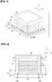
- Figure 1 is a perspective view illustrating the fuel cell 1 according to an embodiment of the present invention.
- Figure 2 is a schematic cross-sectional view illustrating the fuel cell 1 according to the present embodiment.
- Figure 3 is an exploded perspective view of a cell unit 100.
- Figure 4 is a view illustrating the flow of anode gas and cathode gas.
- Figure 5 is an exploded perspective view of a metal support cell assembly 110.
- Figure 6 is a cross-sectional view along line 6-6 of Figure 3 .
- Figure 7 is a cross-sectional view of a fuel cell stack 10.
- Figure 8 is a perspective view illustrating the fuel cell stack 10 and a casing 20.
- Figure 9 is a view for explaining a space 62 provided between the casing 20 and an upper current collector 41.
- Figure 10 is an exploded perspective view of a casing 20 and an upper current collector 41.
- the fuel cell 1 includes the fuel cell stack 10, which is configured by stacking a plurality of cell units 100, each of which includes an electrolyte electrode assembly 111 and a separator 120, and the casing 20 disposed above the fuel cell stack 10 in the Z direction.
- the fuel cell 1 includes an application part 50 that applies stacking force F to the fuel cell stack 10 along the Z direction via the casing 20, and a facilitating mechanism 60 that facilitates the elongation of the casing 20 due to linear expansion.
- the facilitating mechanism 60 has a space (corresponding to a gas flow passage) 62 that is provided between the casing 20 and the upper current collector 41 (corresponding to an end current collector), which is provided at the uppermost portion of the fuel cell stack 10, and that absorbs the linear expansion of the fuel cell stack 10 in the Z direction.
- inclined surfaces 41a, 20a which are inclined relative to the Z direction, are provided on the upper current collector 41 and the casing 20, respectively, and the upper current collector 41 and the casing 20 are connected to each other via the space 62 at the inclined surfaces 41a, 20a.
- the fuel cell 1 has the fuel cell stack 10, the casing 20, the application part 50, and the facilitating mechanism 60.
- the fuel cell stack 10 has a plurality of cell units 100, the upper current collector 41 provided above the cell units 100, and a lower current collector 42 provided below the cell units 100.
- the cell unit 100 is configured by sequentially stacking the metal support cell assembly 110, the separator 120 in which flow passage portions 121 for circulating gas are defined between the electrolyte electrode assembly 111, and an auxiliary current collector layer 130.
- a contact material may be disposed between the metal support cell assembly 110 and the auxiliary current collector layer 130 so as to bring the two into conductive contact, or the auxiliary current collector layer 130 may be omitted.
- the cell unit 100 also has a plurality of seals 160 that seal the peripheries of an anode gas first inflow port 120a, an anode gas second inflow port 120b, and an anode gas first outflow port 120c provided in the separator 120, thereby restricting the flow of gas.
- the metal support cell assembly 110 has a metal support cell (MSC) 110M, which is disposed in the vicinity of the center, and a cell frame 113 that holds the outer circumference of the metal support cell 110M.
- MSC metal support cell
- the metal support cell 110M has the electrolyte electrode assembly 111, which is obtained by sandwiching an electrolyte 111E from both sides between an anode 111A and a cathode 111C, and a metal support portion 112 that is made of metal that supports the electrolyte electrode assembly 111 from one side in the vertical direction.
- the metal support cell 110M has better mechanical strength and rapid activating ability than electrolyte-supported cells and electrode-supported cells.
- the electrolyte electrode assembly 111 is formed by sandwiching the electrolyte layer 111E from both sides between the anode 111A and the cathode 111C.
- the electrolyte 111E allows oxide ions to pass from the cathode 111C to the anode 111A.
- the electrolyte 111E allows oxide ions to pass but does not allow gas and electrons to pass.
- An example of a material forming the electrolyte 111E is a solid oxide ceramic, such as stabilized zirconia, in which yttria, neodymium oxide, samaria, gadria, scandia, and the like have been doped.
- the anode 111A is a fuel electrode and reacts an anode gas (for example, hydrogen) with oxide ions in order to generate oxides of the anode gas and extract electrons.
- the anode 111A is resistant to a reducing atmosphere, allows the anode gas to pass therethrough, has high electrical (electron and ion) conductivity, and has a catalytic action to react the anode gas with the oxide ions.
- Examples of materials for forming the anode 111A include those in which a metal, such as nickel, and an oxide ion conductor, such as yttria-stabilized zirconia, are mixed.
- the cathode 111C is an oxidant electrode and reacts a cathode gas (for example, oxygen contained in air) with electrons to convert oxygen molecules to oxide ions.
- a cathode gas for example, oxygen contained in air
- the cathode 111C is resistant to an oxidizing atmosphere, allows the cathode gas to pass therethrough, has high electrical (electron and ion) conductivity, and has a catalytic action to convert oxygen molecules into oxide ions.
- Examples of materials for forming the cathode 111C include oxides of lanthanum, strontium, manganese, cobalt, and the like.
- the metal support portion 112 supports the electrolyte electrode assembly 111 from the anode 111A side.
- the metal support portion 112 is a porous metal having gas permeability and electrical conductivity. Examples of materials for forming the metal support portion 112 include corrosion-resistant alloys containing nickel and chromium, corrosion-resistant steel, and stainless steel.
- the cell frame 113 holds the metal support cell 110M from the periphery.
- the cell frame 113 has an opening 113H.
- the metal support cell 110M is disposed in the opening 113H of the cell frame 113.
- the outer circumference of the metal support cell 110M is joined to the inner edge of the opening 113H of the cell frame 113.
- Examples of materials for forming the cell frame 113 include metals whose surfaces have been subjected to an insulation treatment.
- the cell frame 113 has an anode gas first inflow port 113a, an anode gas second inflow port 113b, and an anode gas first outflow port 113c, through which ports the anode gas flows.
- a cathode gas first inflow port 113d, a cathode gas first outflow port 113e, and a cathode gas second outflow port 113f, through which ports the cathode gas flows, are formed on the outer circumference of the cell frame 113.
- the cathode gas first inflow port 113d is formed on the outer circumference of the cell frame 113 between the anode gas first inflow port 113a and the anode gas second inflow port 113b.
- the cathode gas first outflow port 113e and the cathode gas second outflow port 113f are formed on the outer circumference of the cell frame 113 on one side and the other of the anode gas first outflow port 113c.
- the cathode gas first inflow port 113d, the cathode gas first outflow port 113e, and the cathode gas second outflow port 113f, through which ports the cathode gas flows, are formed in a space V that is formed between the inner circumferential surface of an upper casing hood 51 of the application part 50, described further below, and the outer circumferential surface of the fuel cell stack 10, as shown in Figure 2 .
- the separator 120 is disposed between the metal support cells 110M, which are adjacent to each other in the Z direction.
- the separator 120 has flow passage portions 121 in a region opposing the electrolyte electrode assembly 111 of the metal support cell 110M.
- the flow passage portions 121 have convex-concave shapes that define flow passages for gas with the electrolyte electrode assembly 111.
- An example of a material for forming the separator 120 is metal.
- An insulation treatment is applied to the regions of the separator 120 except the flow passage portions 121.
- the flow passage portions 121 of the separator 120 are formed in an essentially linear shape such that the convex-concave shapes extend in the Y direction. As a result, the direction of flow of the gas that flows along the flow passage portions 121 is the X direction.
- the separator 120 has an anode gas first inflow port 120a, an anode gas second inflow port 120b, and an anode gas first outflow port 120c, through which ports the anode gas flows.
- a cathode gas first inflow port 120d, a cathode gas first outflow port 120e, and a cathode gas second outflow port 120f, through which ports the cathode gas flows are formed on the outer circumference of the separator 120.
- the cathode gas first inflow port 120d is formed on the outer circumference of the separator 120 between the anode gas first inflow port 120a and the anode gas second inflow port 120b.
- the cathode gas first outflow port 120e and the cathode gas second outflow port 120f are formed on the outer circumference of the separator 120 on one side and the other of the anode gas first outflow port 120c.
- the cathode gas first inflow port 120d, the cathode gas first outflow port 120e, and the cathode gas second outflow port 120f, through which ports the cathode gas flows, are formed in the space V that is formed between the inner circumferential surface of an upper casing hood 51 of the application part 50, described further below, and the outer circumferential surface of the fuel cell stack 10, as shown in Figure 2 .
- the auxiliary current collector layer 130 is disposed between the metal support cell 110M and the separator 120, forms a space through which gas passes, equalizes surface pressure, and the like, and assists the electrical contact between the metal support cell 110M and the separator 120.
- the auxiliary current collector layer 130 is a wire mesh expanded metal, for example.
- the auxiliary current collector layer can be omitted if its characteristics and functions can be realized by another element.
- the seal 160 is formed from a material with heat resistance and sealing properties.
- a material with heat resistance and sealing properties is Thermiculite (registered trademark), the main material of which is vermiculite (vermiculite).
- vermiculite vermiculite
- the upper current collector 41 outputs the electrical power that is generated by the cell unit 100 to the outside.
- the upper current collector 41 has the same outer shape as the cell unit 100.
- the upper current collector 41 is provided with a terminal (not shown) that is connected to an external current source.
- the upper current collector 41 is made from a conductive material that does not allow gas permeation, and, except for the terminal portion and regions that oppose the electrolyte electrode assembly 111 of the cell unit 100, is insulated with an insulating material or a coating.
- the insulating material is formed, for example, by fixing aluminum oxide onto the upper current collector 41.
- the upper current collector 41 has an inclined surface 41a, which is inclined with respect to the Z direction such that the width decreases upwardly in the Z direction.
- the inclined surface 41a is formed in the X direction. At room temperature, the inclined surface 41a is connected (engaged) with an inclined surface 20a provided on the casing 20.
- the lower current collector 42 outputs the electrical power generated by the cell unit 100 to the outside.
- the lower current collector 42 has the same outer shape as the cell unit 100.
- the lower current collector 42 is provided with a terminal (not shown) that is connected to an external current source.
- the lower current collector 42 is made from a conductive material that does not allow gas permeation, and, except for the terminal portion and regions that oppose the electrolyte electrode assembly 111 of the cell unit 100, is insulated using an insulating material or a coating.
- the insulating material is formed by fixing aluminum oxide onto the lower current collector 42, for example.
- the casing 20 is disposed above the fuel cell stack 10 in the Z direction.
- the casing 20 is made from a conductive material that does not allow gas permeation.
- the casing 20 is made of metal, for example.
- the casing 20 includes a flat surface portion 21 in the XY plane, a first extension portion 22 and a second extension portion 23 that extend from both ends of the flat surface portion 21 in the Y direction and that extend downward in the Z direction, and a groove portion 24 provided between the first extension portion 22 and the second extension portion 23.
- the inclined surface 20a which is inclined with respect to the Z direction such that the width decreases upwardly in the Z direction, is provided on the inward side of the first extension portion 22 and the second extension portion 23 of the casing 20 in the Y direction.
- the groove portion 24 is configured such that the space 62 is formed between the casing 20 and the upper current collector 41 at room temperature. In addition, the groove portion 24 is configured such that the space 62 between the casing 20 and the upper current collector 41 is sealed when the fuel cell 1 is heated (refer to Figures 11 and 12 ).
- the coefficient of linear expansion of the casing 20 is preferably greater than the coefficient of linear expansion of the upper current collector 41.
- the application part 50 applies the stacking force F to the fuel cell stack 10 along the Z direction (refer to Figure2 ). As shown in Figures 1 and 2 , the application part 50 includes the upper casing hood 51, a lower casing hood 52, and a fastener 53.
- the upper casing hood 51 forms the space V, which is the cathode gas flow passage, with the fuel cell stack 10.
- the upper casing hood 51 covers the fuel cell stack 10 and the casing 20 from above.
- the upper casing hood 51 is box-shaped with an open lower portion.
- the upper casing hood 51 has a collar portion 511 that extends outwardly in the XY plane.
- a through-hole (not shown), through which the fastener 53 passes, is formed on the collar portion 511 in the Z direction.
- the upper casing hood 51 is made of metal, for example, and the interior surface is insulated with an insulating material or a coating.
- the insulating material is formed, for example, by fixing aluminum oxide onto the upper casing hood 51.
- FIG. 2 shows the lower casing hood 52, which is provided for externally supplying/discharging cathode gas to/from the plurality of cell units 100.
- the lower casing hood 52 has a cathode gas inflow hole 52a into which the cathode gas flows, and a cathode gas outflow hole 52b from which the cathode gas flows out.
- the lower casing hood 52 is provided below the lower current collector 42. As viewed from the Z direction, the lower casing hood 52 has the same shape as the collar portion 511 of the upper casing hood 51.
- the lower casing hood 52 is provided with through-holes that are formed in the Z direction in locations that correspond to the through-holes formed in the collar portion 511.
- the fastener 53 are inserted into the through-holes provided in the collar portion 511 of the upper casing hood 51 and the through-holes provided in the lower casing hood 52.
- the fastener 53 are nuts and bolts.
- the facilitating mechanism 60 facilitates the elongation of the casing 20 due to linear expansion.
- the facilitating mechanism 60 has a heater 61 for heating the cathode gas and a gas flow passage 62 through which the cathode gas heated by the heater 61 flows.
- the facilitating mechanism 60 also has a blower 63 that supplies the cathode gas heated by the heater 61 to the space V that is formed between the upper casing hood 51 and the fuel cell stack 10.
- the heater 61 heats the cathode gas that flows into the space V that is formed between the upper casing hood 51 and the fuel cell stack 10.
- a heat exchanger included in a common fuel cell system may be used as the heater 61.
- the gas flow passage 62 is provided between the casing 20 and the upper current collector 41.
- the gas flow passage 62 is formed in the X direction.
- the gas flow passage 62 is provided in communication with the space V that is formed between the upper casing hood 51 and the fuel cell stack 10.
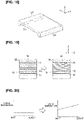
- Figure 11 is a view illustrating the states before (left figure) and after (right figure) the groove portion 24 of the casing 20 extends in the Y direction.
- Figure 12 is a partially enlarged view illustrating the states before (left figure) and after (right figure) the groove portion 24 of the casing 20 extends in the Y direction.
- Figure 13 is a view for explaining the distribution along the X direction of the extension lengths of the groove portion 24 of the casing 20 along the Y direction.
- Figure 14 shows graphs illustrating the temperature distribution of the casing 20 at room temperature (left graph) and during heating (right graph).
- Figure 15 is a side view of the fuel cell 1 at room temperature (left figure) and during heating (right figure).
- the cathode gas heated by the heater 61 is supplied to the space V that is formed between the upper casing hood 51 and the fuel cell stack 10 (refer to Figure 2 ). Then the cathode gas supplied to the space V flows into the flow passage portions 121 of the fuel cell stack 10 and the gas flow passage 62 connected to the space V.
- the electrolyte electrode assembly 111 expands linearly in the Z direction.
- the groove portion 24 of the casing 20 extends in the Y direction.
- the upper current collector 41 moves toward the casing 20 such that the inclined surface 41a of the upper current collector 41 moves along the inclined surface 20a of the casing 20 (refer to Figure 9 ). Therefore, since the elongation of the electrolyte electrode assembly 111 due to the linear expansion in the Z direction is absorbed, it is possible to suitably prevent an excessively compressive load from acting on the electrolyte electrode assembly 111.
- the temperature of the cathode gas that flows into the gas flow passage 62 gradually decreases from the inlet side of the gas flow passage 62 (lower left side of Figure 13 ) to the outlet side of the gas flow passage 62 (upper right side of Figure 13 ). For this reason, as shown in Figure 14 , whereas at room temperature, the temperature of the casing 20 is uniform from the inlet to the outlet (left side of Figure 14 ), during heating, the overall temperature of the casing 20 increases, gradually decreasing from the inlet to the outlet (right side of Figure 14 ).Thus, as indicated by the hollow arrows in Figure 13 , the elongation of the groove portion 24 of the casing 20 in the Y direction is greater on the inlet side of the gas flow passage 62 than on the outlet side of the gas flow passage 62.
- the in-plane temperature distribution of the casing 20 in the XY plane during heating becomes similar to the in-plane temperature distribution of the electrolyte electrode assembly 111. That is, the locations of greatest elongation of the electrolyte electrode assembly 111 in the Z direction correspond to the locations of greatest extension of the casing 20 in the Y direction. Thus, it is possible to prevent an excessively compressive load from acting on the electrolyte electrode assembly 111 across the entire region of the XY plane.
- the upper current collector 41 moves toward the casing 20 in order to seal the gas flow passage 62.
- the configuration is such that the gas flow passage 62 is not sealed when the upper current collector 41 moves toward the casing 20
- the fuel cell stack could unintendedly be cooled by the gas that flows into the gas flow passage 62 during power generation operation after heating, thereby reducing the performance of the fuel cell.
- the fuel cell 1 of the present embodiment since the gas flow passage 62 is sealed during heating, it is possible to prevent the unintended cooling of the fuel cell stack 10.
- a configuration in which the gas flow passage 62 is not sealed when the upper current collector 41 moves toward the casing 20 is also included in the present invention.
- Figure 16 is a schematic overview illustrating the fuel cell system 200.
- the anode gas is supplied to the fuel cell stack 10.
- the cathode gas is supplied to the fuel cell stack 10 via the heater 61.
- a first thermometer 220 is installed in the fuel cell stack 10 to measure the temperature inside the fuel cell stack 10.
- the anode gas and the cathode gas discharged from the fuel cell stack 10 are discharged via an exhaust heat exchanger 240.
- a second thermometer 230 is installed in a pipe through which the cathode gas flows between the fuel cell stack 10 and the exhaust heat exchanger 240 to measure the temperature of the cathode gas in the pipe.
- a control unit 210 controls the heater 61, the reading of the first thermometer 220 and the second thermometer 230, etc.
- Figure 17 is a flow chart illustrating the method for using the fuel cell system 200.
- Step S01 it is determined whether it is necessary to heat the fuel cell stack 10 (Step S01). If a NO determination is made in Step S01, the process proceeds to Step S05. Step S05 will be described further below. On the other hand, if a YES determination is made in Step S01, the process proceeds to Step S02.
- Step S02 the cathode gas is supplied.
- the heater 61 is then activated by the control unit 210.
- Step S04 It is then determined whether the temperature of the cathode gas outflow port of the fuel cell stack 10 is greater than or equal to a prescribed temperature Ts (step S04). If a NO determination is made in Step S04, the control is ended. On the other hand, if a YES determination is made in Step S04, the process proceeds to Step S05.
- Step S05 an operation to generate power with the fuel cell stack 10 is carried out. After the steps described above, the control of the fuel cell system 200 ends.
- the fuel cell 1 includes the fuel cell stack 10 configured by stacking a plurality of the cell units 100, each including the electrolyte electrode assembly 111 and the separator 120.
- the fuel cell 1 also includes the casing 20 disposed above the fuel cell stack 10 in the Z direction, and the application part 50 that applies the stacking force F to the fuel cell stack 10 in the Z direction via the casing 20.
- the fuel cell 1 further includes the facilitating mechanism 60 that facilitates the elongation of the casing 20 due to linear expansion.
- the facilitating mechanism 60 includes the space 62 that is provided between the casing 20 and the upper current collector 41, which is provided at the uppermost portion of the fuel cell stack 10, and that absorbs the linear expansion of the fuel cell stack 10 in the Z direction.
- the inclined surfaces 41a, 20a which are inclined relative to the Z direction, are provided on the upper current collector 41 and the casing 20, respectively.
- the upper current collector 41 and the casing 20 are interconnected via the space 62 at the inclined surfaces 41a, 20a.
- the facilitating mechanism 60 further includes the heater 61 for heating the gas.
- the space 62 is the gas flow passage 62 through which the gas heated by the heater 61 flows.
- the heated gas flows through the gas flow passage 62 in order to facilitate the elongation of the casing 20 due to linear expansion.
- the upper current collector 41 enters into the space 62.
- the gas that flows through the gas flow passage 62 is heating gas that flows inside the fuel cell stack 10 when the fuel cell stack 10 is activated.
- the heating gas for activating the fuel cell stack 10 flows through the gas flow passage 62. Therefore, as described above, the in-plane temperature distribution of the casing 20 in the XY plane during heating becomes the same as the in-plane temperature distribution of the electrolyte electrode assembly 111. Thus, it is possible to prevent an excessively compressive load from acting on the electrolyte electrode assembly 111 across the entire region of the XY plane.
- the gas flow passage 62 which is provided in communication with the space V that is formed between the application part 50 and the fuel cell stack 10, serves as the cathode gas flow passage.
- the upper current collector 41 moves toward the casing 20 in order to seal the gas flow passage 62.
- the fuel cell 1 configured in this manner, it is possible to prevent the upper current collector 41 from being unintentionally cooled by the cathode gas during operation.
- the coefficient of linear expansion of the casing 20 is greater than the coefficient of linear expansion of the upper current collector 41.
- the fuel cell 1 according to the present invention was described by using the embodiment above, but the present invention is not limited to the content described in the embodiment and may be appropriately modified based on the descriptions of the Claims.
- the groove portion 24 of the casing 20 is configured to have the same height from the inlet to the outlet, as shown in Figure 10 .
- a groove portion 324 of a casing 320 may be configured to be inclined with respect to the X direction (flow direction) such that the outlet is higher than the inlet.
- the linear expansion of the fuel cell stack 10 in the Z direction can be absorbed up to a higher temperature on the outlet side than on the inlet side.
- the linear expansion of the fuel cell stack 10 in the Z direction can be absorbed during operation in which the temperature on the outlet side is higher than that on the inlet side.
- the surface of the casing 20 opposing the gas flow passage 62 has a planar shape.
- convex-concave shapes can be successively formed on a surface 420a of a casing 420 opposing a gas flow passage 462.
- the fuel cell stack 10 has an open cathode type structure, but the cathode gas flow passage may have an internal manifold type structure.
- the gas flow passage 62 is formed only above the upper current collector 41, but in addition to or instead of this, a gas flow passage may be formed below the lower current collector 42.
- the inclined surfaces 41a, 20a are provided that have a continuously tapered shape.
- the inclined surfaces may be formed with a stepwise shape.
- the cathode gas is supplied to the gas flow passage 62 at the time of startup in order to linearly expand the casing 20 in the Y direction.
- a separate heating gas independent of the fuel cell system 200 may be supplied in order to linearly expand the casing 20 in the Y direction.
Landscapes
- Engineering & Computer Science (AREA)
- Chemical & Material Sciences (AREA)
- Life Sciences & Earth Sciences (AREA)
- Manufacturing & Machinery (AREA)
- Sustainable Development (AREA)
- Sustainable Energy (AREA)
- Chemical Kinetics & Catalysis (AREA)
- Electrochemistry (AREA)
- General Chemical & Material Sciences (AREA)
- Combustion & Propulsion (AREA)
- Fuel Cell (AREA)
Claims (10)
- Pile à combustible à oxyde solide (1), comprenant :un assemblage de piles à combustible (10) réalisé par empilement d'une pluralité d'unités de pile (100), chacune desdites unités de pile comprenant un ensemble électrode-électrolyte (111) et un séparateur (120) ;un boîtier (20) disposé sur un côté d'extrémité de l'assemblage de piles à combustible dans la direction d'empilement (Z) ;une section d'application (50) appliquant une force d'empilement (F) sur l'assemblage de piles à combustible dans la direction d'empilement par l'intermédiaire du boîtier ; etun mécanisme de facilitation (60) facilitant l'élongation du boîtier en raison d'une dilatation linéaire, où ledit mécanisme de facilitation présente un espace (62) prévu entre le boîtier et un collecteur de courant d'extrémité (41), disposé dans une partie d'extrémité sur un côté d'extrémité de l'assemblage de piles à combustible, et absorbant la dilatation linéaire de l'assemblage de piles à combustible dans la direction d'empilement, et où le collecteur de courant d'extrémité et le boîtier présentent chacun une surface inclinée (41a, 20a) par rapport à la direction d'empilement, et la plaque de collecteur de courant d'extrémité et le boîtier sont reliés sur leurs surfaces inclinées par l'intermédiaire de l'espace ;caractérisée en ce quele mécanisme de facilitation comprend en outre un dispositif de chauffage (61) pour chauffer du gaz, et l'espace est un passage d'écoulement gazeux par où s'écoule le gaz chauffé par le dispositif de chauffage.
- Pile à combustible à oxyde solide selon la revendication 1, où la surface inclinée du collecteur de courant d'extrémité a une forme effilée de façon continue.
- Pile à combustible à oxyde solide selon la revendication 1 ou 2, où le gaz s'écoulant dans le passage d'écoulement gazeux est un gaz de chauffage circulant à l'intérieur de l'assemblage de piles à combustible lorsque l'assemblage de piles à combustible est activé.
- Pile à combustible à oxyde solide selon l'une des revendications 1 à 3, où le passage d'écoulement gazeux est prévu en communication avec un espace formé entre la section d'application et l'assemblage de piles à combustible pour servir de passage d'écoulement gazeux cathodique.
- Pile à combustible à oxyde solide selon l'une des revendications 1 à 4, où le collecteur de courant d'extrémité se déplace vers le boîtier pour fermer le passage d'écoulement gazeux quand l'assemblage de piles à combustible se dilate linéairement dans la direction d'empilement en cours de fonctionnement.
- Pile à combustible à oxyde solide selon l'une des revendications 1 à 5, où le boîtier a un coefficient de dilatation linéaire supérieur au coefficient de dilatation linéaire du collecteur de courant d'extrémité.
- Pile à combustible à oxyde solide selon l'une des revendications 1 à 6, où une forme convexe-concave est successivement formée sur une surface du boîtier opposée au passage d'écoulement gazeux en vue dans la direction d'écoulement du gaz.
- Pile à combustible à oxyde solide selon l'une des revendications 1 à 7, où le passage d'écoulement gazeux est prévu de manière à être incliné par rapport à la direction d'écoulement gazeux de sorte que la hauteur du passage d'écoulement gazeux sur un côté de sortie du passage d'écoulement gazeux est supérieure à celle sur un côté d'entrée du passage d'écoulement gazeux.
- Pile à combustible à oxyde solide selon l'une des revendications 1 à 8, oùle collecteur de courant d'extrémité a la même forme extérieure que chaque unité de la pluralité d'unités de pile en vue dans la direction d'empilement ;le collecteur de courant d'extrémité est pourvu d'une borne connectée à une source de courant extérieur ; etle collecteur de courant d'extrémité est constitué d'un matériau conducteur ne permettant pas la pénétration de gaz, et est isolé par un matériau isolant ou un revêtement, à l'exception d'une partie de borne et de zones opposées à l'ensemble électrode-électrolyte.
- Pile à combustible à oxyde solide selon l'une des revendications 1 à 9, où
l'assemblage de piles à combustible recourt à un matériau d'oxyde solide en tant qu'électrolyte, lequel recourt à un conducteur d'ions d'oxyde.
Applications Claiming Priority (1)
| Application Number | Priority Date | Filing Date | Title |
|---|---|---|---|
| PCT/JP2018/013443 WO2019186959A1 (fr) | 2018-03-29 | 2018-03-29 | Pile à combustible à oxyde solide |
Publications (3)
| Publication Number | Publication Date |
|---|---|
| EP3780209A1 EP3780209A1 (fr) | 2021-02-17 |
| EP3780209A4 EP3780209A4 (fr) | 2021-05-26 |
| EP3780209B1 true EP3780209B1 (fr) | 2022-06-08 |
Family
ID=68059629
Family Applications (1)
| Application Number | Title | Priority Date | Filing Date |
|---|---|---|---|
| EP18912421.7A Active EP3780209B1 (fr) | 2018-03-29 | 2018-03-29 | Pile à combustible à oxyde solide |
Country Status (5)
| Country | Link |
|---|---|
| US (1) | US11322770B2 (fr) |
| EP (1) | EP3780209B1 (fr) |
| JP (1) | JP6973622B2 (fr) |
| CN (1) | CN111937207B (fr) |
| WO (1) | WO2019186959A1 (fr) |
Families Citing this family (2)
| Publication number | Priority date | Publication date | Assignee | Title |
|---|---|---|---|---|
| AT526002B1 (de) * | 2022-04-14 | 2023-12-15 | Avl List Gmbh | Dichtvorrichtung für zumindest einen Brennstoffzellenstapel |
| JP7530123B1 (ja) | 2023-07-21 | 2024-08-07 | 株式会社水素パワー | 燃料電池 |
Family Cites Families (15)
| Publication number | Priority date | Publication date | Assignee | Title |
|---|---|---|---|---|
| JPH06188023A (ja) * | 1992-12-22 | 1994-07-08 | Fuji Electric Co Ltd | 平板形固体電解質燃料電池 |
| US6428921B1 (en) * | 1999-10-22 | 2002-08-06 | General Motors Corporation | Fuel cell stack compression method and apparatus |
| JP3614110B2 (ja) * | 2001-02-21 | 2005-01-26 | 日産自動車株式会社 | 燃料電池システム |
| ATE375011T1 (de) * | 2003-02-23 | 2007-10-15 | Tribecraft Ag | Endplatte für einen stapeln von brennstoffzellen |
| JP2006173055A (ja) | 2004-12-20 | 2006-06-29 | Nissan Motor Co Ltd | ワーク保持装置 |
| ES2385902T3 (es) | 2006-07-14 | 2012-08-02 | Topsoe Fuel Cell A/S | Conjunto de compresión, bloque de pilas de combustible de óxido sólido, un procedimiento para la compresión del bloque de pilas de combustible de óxido sólido y su utilización |
| ATE469447T1 (de) | 2007-01-26 | 2010-06-15 | Topsoe Fuel Cell As | Brennstoffzellenstapel-klemmstruktur und festoxid-brennstoffzellenstapel |
| JP2008305686A (ja) | 2007-06-08 | 2008-12-18 | Toyota Motor Corp | 燃料電池システム |
| WO2009017147A1 (fr) * | 2007-08-02 | 2009-02-05 | Sharp Kabushiki Kaisha | Empilement de piles à combustible et système de pile à combustible |
| JP5269480B2 (ja) | 2008-05-27 | 2013-08-21 | 本田技研工業株式会社 | 燃料電池スタック |
| JP5203162B2 (ja) | 2008-12-09 | 2013-06-05 | 本田技研工業株式会社 | 燃料電池スタックの積層荷重調整装置 |
| EP2530772B1 (fr) | 2010-01-26 | 2016-09-07 | Kyocera Corporation | Pile à combustible, dispositif de pile à combustible, module de pile à combustible et système de pile à combustible |
| CA2909568C (fr) * | 2013-04-15 | 2016-11-22 | Nissan Motor Co., Ltd. | Procede de fabrication et dispositif de fabrication d'un coeur de pile a combustible |
| JP6290676B2 (ja) | 2014-03-25 | 2018-03-07 | 東京瓦斯株式会社 | 燃料電池 |
| JP2017107664A (ja) | 2015-12-07 | 2017-06-15 | 株式会社Soken | 燃料電池 |
-
2018
- 2018-03-29 EP EP18912421.7A patent/EP3780209B1/fr active Active
- 2018-03-29 WO PCT/JP2018/013443 patent/WO2019186959A1/fr not_active Ceased
- 2018-03-29 CN CN201880092048.6A patent/CN111937207B/zh active Active
- 2018-03-29 US US17/042,275 patent/US11322770B2/en active Active
- 2018-03-29 JP JP2020508755A patent/JP6973622B2/ja active Active
Also Published As
| Publication number | Publication date |
|---|---|
| EP3780209A4 (fr) | 2021-05-26 |
| JP6973622B2 (ja) | 2021-12-01 |
| US11322770B2 (en) | 2022-05-03 |
| JPWO2019186959A1 (ja) | 2021-02-25 |
| CN111937207A (zh) | 2020-11-13 |
| CN111937207B (zh) | 2021-10-08 |
| WO2019186959A1 (fr) | 2019-10-03 |
| EP3780209A1 (fr) | 2021-02-17 |
| US20210057772A1 (en) | 2021-02-25 |
Similar Documents
| Publication | Publication Date | Title |
|---|---|---|
| JP6517835B2 (ja) | 燃料電池スタック構成 | |
| US10297854B2 (en) | Fuel cell stack | |
| US20030235752A1 (en) | Oxygen getters for anode protection in a solid-oxide fuel cell stack | |
| EP3309884B1 (fr) | Unité de réaction électro-chimique et empilement de piles à combustible | |
| JP6118230B2 (ja) | 燃料電池スタック | |
| JP2009505370A (ja) | 移動式発電機用の固体酸化物形燃料セルスタック | |
| EP3780209B1 (fr) | Pile à combustible à oxyde solide | |
| KR101409509B1 (ko) | 고체산화물 연료전지용 집전체와 이를 적용한 고체산화물 연료전지 | |
| US11069915B2 (en) | Spring member, fuel cell unit, and fuel cell stack | |
| JP6777669B2 (ja) | 電気化学反応セルスタックの運転方法および電気化学反応システム | |
| US11870080B2 (en) | Anode layer activation method for solid oxide fuel cell, and solid oxide fuel cell system | |
| JP2023144595A (ja) | 電気化学反応セルスタック | |
| JP7087624B2 (ja) | 燃料電池スタック | |
| KR20130083278A (ko) | 연료전지용 막전극접합체 | |
| US11411275B2 (en) | Spring member, fuel cell unit, fuel cell stack, and method for manufacturing fuel cell stack | |
| JPH06342663A (ja) | 固体電解質型燃料電池 | |
| CN111052474B (zh) | 燃料电池的堆构造和燃料电池堆的热应变吸收方法 | |
| JP2022073494A (ja) | 電気化学反応セルスタック | |
| US12080925B1 (en) | Electrochemical cell system containing air baffle assembly with air bypass mitigation features and method of operating thereof | |
| JP6389959B2 (ja) | 燃料電池スタックおよび燃料電池スタックの製造方法 | |
| US20240313243A1 (en) | Electrochemical cell, current collector, and cell stack | |
| JP2013222505A (ja) | 燃料電池およびその製造方法 | |
| US11398638B2 (en) | Cell structure for fuel cell and fuel cell system | |
| JP2024056240A (ja) | 電気化学反応セルスタック | |
| JP2024063296A (ja) | 電気化学反応単セル |
Legal Events
| Date | Code | Title | Description |
|---|---|---|---|
| STAA | Information on the status of an ep patent application or granted ep patent |
Free format text: STATUS: THE INTERNATIONAL PUBLICATION HAS BEEN MADE |
|
| PUAI | Public reference made under article 153(3) epc to a published international application that has entered the european phase |
Free format text: ORIGINAL CODE: 0009012 |
|
| STAA | Information on the status of an ep patent application or granted ep patent |
Free format text: STATUS: REQUEST FOR EXAMINATION WAS MADE |
|
| 17P | Request for examination filed |
Effective date: 20201028 |
|
| AK | Designated contracting states |
Kind code of ref document: A1 Designated state(s): AL AT BE BG CH CY CZ DE DK EE ES FI FR GB GR HR HU IE IS IT LI LT LU LV MC MK MT NL NO PL PT RO RS SE SI SK SM TR |
|
| AX | Request for extension of the european patent |
Extension state: BA ME |
|
| A4 | Supplementary search report drawn up and despatched |
Effective date: 20210428 |
|
| RIC1 | Information provided on ipc code assigned before grant |
Ipc: H01M 8/248 20160101AFI20210421BHEP Ipc: H01M 8/04014 20160101ALI20210421BHEP Ipc: H01M 8/12 20160101ALI20210421BHEP Ipc: H01M 8/2432 20160101ALI20210421BHEP Ipc: H01M 8/2475 20160101ALI20210421BHEP Ipc: H01M 8/124 20160101ALN20210421BHEP |
|
| DAV | Request for validation of the european patent (deleted) | ||
| DAX | Request for extension of the european patent (deleted) | ||
| GRAP | Despatch of communication of intention to grant a patent |
Free format text: ORIGINAL CODE: EPIDOSNIGR1 |
|
| STAA | Information on the status of an ep patent application or granted ep patent |
Free format text: STATUS: GRANT OF PATENT IS INTENDED |
|
| RIC1 | Information provided on ipc code assigned before grant |
Ipc: H01M 8/124 20160101ALN20220228BHEP Ipc: H01M 8/2475 20160101ALI20220228BHEP Ipc: H01M 8/2432 20160101ALI20220228BHEP Ipc: H01M 8/12 20160101ALI20220228BHEP Ipc: H01M 8/04014 20160101ALI20220228BHEP Ipc: H01M 8/248 20160101AFI20220228BHEP |
|
| RIC1 | Information provided on ipc code assigned before grant |
Ipc: H01M 8/124 20160101ALN20220311BHEP Ipc: H01M 8/2475 20160101ALI20220311BHEP Ipc: H01M 8/2432 20160101ALI20220311BHEP Ipc: H01M 8/12 20160101ALI20220311BHEP Ipc: H01M 8/04014 20160101ALI20220311BHEP Ipc: H01M 8/248 20160101AFI20220311BHEP |
|
| INTG | Intention to grant announced |
Effective date: 20220329 |
|
| GRAS | Grant fee paid |
Free format text: ORIGINAL CODE: EPIDOSNIGR3 |
|
| GRAA | (expected) grant |
Free format text: ORIGINAL CODE: 0009210 |
|
| STAA | Information on the status of an ep patent application or granted ep patent |
Free format text: STATUS: THE PATENT HAS BEEN GRANTED |
|
| AK | Designated contracting states |
Kind code of ref document: B1 Designated state(s): AL AT BE BG CH CY CZ DE DK EE ES FI FR GB GR HR HU IE IS IT LI LT LU LV MC MK MT NL NO PL PT RO RS SE SI SK SM TR |
|
| REG | Reference to a national code |
Ref country code: AT Ref legal event code: REF Ref document number: 1497544 Country of ref document: AT Kind code of ref document: T Effective date: 20220615 Ref country code: CH Ref legal event code: EP |
|
| REG | Reference to a national code |
Ref country code: DE Ref legal event code: R096 Ref document number: 602018036652 Country of ref document: DE |
|
| REG | Reference to a national code |
Ref country code: IE Ref legal event code: FG4D |
|
| REG | Reference to a national code |
Ref country code: LT Ref legal event code: MG9D |
|
| REG | Reference to a national code |
Ref country code: NL Ref legal event code: MP Effective date: 20220608 |
|
| PG25 | Lapsed in a contracting state [announced via postgrant information from national office to epo] |
Ref country code: SE Free format text: LAPSE BECAUSE OF FAILURE TO SUBMIT A TRANSLATION OF THE DESCRIPTION OR TO PAY THE FEE WITHIN THE PRESCRIBED TIME-LIMIT Effective date: 20220608 Ref country code: NO Free format text: LAPSE BECAUSE OF FAILURE TO SUBMIT A TRANSLATION OF THE DESCRIPTION OR TO PAY THE FEE WITHIN THE PRESCRIBED TIME-LIMIT Effective date: 20220908 Ref country code: LT Free format text: LAPSE BECAUSE OF FAILURE TO SUBMIT A TRANSLATION OF THE DESCRIPTION OR TO PAY THE FEE WITHIN THE PRESCRIBED TIME-LIMIT Effective date: 20220608 Ref country code: HR Free format text: LAPSE BECAUSE OF FAILURE TO SUBMIT A TRANSLATION OF THE DESCRIPTION OR TO PAY THE FEE WITHIN THE PRESCRIBED TIME-LIMIT Effective date: 20220608 Ref country code: GR Free format text: LAPSE BECAUSE OF FAILURE TO SUBMIT A TRANSLATION OF THE DESCRIPTION OR TO PAY THE FEE WITHIN THE PRESCRIBED TIME-LIMIT Effective date: 20220909 Ref country code: FI Free format text: LAPSE BECAUSE OF FAILURE TO SUBMIT A TRANSLATION OF THE DESCRIPTION OR TO PAY THE FEE WITHIN THE PRESCRIBED TIME-LIMIT Effective date: 20220608 Ref country code: BG Free format text: LAPSE BECAUSE OF FAILURE TO SUBMIT A TRANSLATION OF THE DESCRIPTION OR TO PAY THE FEE WITHIN THE PRESCRIBED TIME-LIMIT Effective date: 20220908 |
|
| REG | Reference to a national code |
Ref country code: AT Ref legal event code: MK05 Ref document number: 1497544 Country of ref document: AT Kind code of ref document: T Effective date: 20220608 |
|
| PG25 | Lapsed in a contracting state [announced via postgrant information from national office to epo] |
Ref country code: RS Free format text: LAPSE BECAUSE OF FAILURE TO SUBMIT A TRANSLATION OF THE DESCRIPTION OR TO PAY THE FEE WITHIN THE PRESCRIBED TIME-LIMIT Effective date: 20220608 Ref country code: LV Free format text: LAPSE BECAUSE OF FAILURE TO SUBMIT A TRANSLATION OF THE DESCRIPTION OR TO PAY THE FEE WITHIN THE PRESCRIBED TIME-LIMIT Effective date: 20220608 |
|
| PG25 | Lapsed in a contracting state [announced via postgrant information from national office to epo] |
Ref country code: NL Free format text: LAPSE BECAUSE OF FAILURE TO SUBMIT A TRANSLATION OF THE DESCRIPTION OR TO PAY THE FEE WITHIN THE PRESCRIBED TIME-LIMIT Effective date: 20220608 |
|
| PG25 | Lapsed in a contracting state [announced via postgrant information from national office to epo] |
Ref country code: SM Free format text: LAPSE BECAUSE OF FAILURE TO SUBMIT A TRANSLATION OF THE DESCRIPTION OR TO PAY THE FEE WITHIN THE PRESCRIBED TIME-LIMIT Effective date: 20220608 Ref country code: SK Free format text: LAPSE BECAUSE OF FAILURE TO SUBMIT A TRANSLATION OF THE DESCRIPTION OR TO PAY THE FEE WITHIN THE PRESCRIBED TIME-LIMIT Effective date: 20220608 Ref country code: RO Free format text: LAPSE BECAUSE OF FAILURE TO SUBMIT A TRANSLATION OF THE DESCRIPTION OR TO PAY THE FEE WITHIN THE PRESCRIBED TIME-LIMIT Effective date: 20220608 Ref country code: PT Free format text: LAPSE BECAUSE OF FAILURE TO SUBMIT A TRANSLATION OF THE DESCRIPTION OR TO PAY THE FEE WITHIN THE PRESCRIBED TIME-LIMIT Effective date: 20221010 Ref country code: ES Free format text: LAPSE BECAUSE OF FAILURE TO SUBMIT A TRANSLATION OF THE DESCRIPTION OR TO PAY THE FEE WITHIN THE PRESCRIBED TIME-LIMIT Effective date: 20220608 Ref country code: EE Free format text: LAPSE BECAUSE OF FAILURE TO SUBMIT A TRANSLATION OF THE DESCRIPTION OR TO PAY THE FEE WITHIN THE PRESCRIBED TIME-LIMIT Effective date: 20220608 Ref country code: CZ Free format text: LAPSE BECAUSE OF FAILURE TO SUBMIT A TRANSLATION OF THE DESCRIPTION OR TO PAY THE FEE WITHIN THE PRESCRIBED TIME-LIMIT Effective date: 20220608 Ref country code: AT Free format text: LAPSE BECAUSE OF FAILURE TO SUBMIT A TRANSLATION OF THE DESCRIPTION OR TO PAY THE FEE WITHIN THE PRESCRIBED TIME-LIMIT Effective date: 20220608 |
|
| PG25 | Lapsed in a contracting state [announced via postgrant information from national office to epo] |
Ref country code: PL Free format text: LAPSE BECAUSE OF FAILURE TO SUBMIT A TRANSLATION OF THE DESCRIPTION OR TO PAY THE FEE WITHIN THE PRESCRIBED TIME-LIMIT Effective date: 20220608 Ref country code: IS Free format text: LAPSE BECAUSE OF FAILURE TO SUBMIT A TRANSLATION OF THE DESCRIPTION OR TO PAY THE FEE WITHIN THE PRESCRIBED TIME-LIMIT Effective date: 20221008 |
|
| REG | Reference to a national code |
Ref country code: DE Ref legal event code: R097 Ref document number: 602018036652 Country of ref document: DE |
|
| PG25 | Lapsed in a contracting state [announced via postgrant information from national office to epo] |
Ref country code: AL Free format text: LAPSE BECAUSE OF FAILURE TO SUBMIT A TRANSLATION OF THE DESCRIPTION OR TO PAY THE FEE WITHIN THE PRESCRIBED TIME-LIMIT Effective date: 20220608 |
|
| PLBE | No opposition filed within time limit |
Free format text: ORIGINAL CODE: 0009261 |
|
| STAA | Information on the status of an ep patent application or granted ep patent |
Free format text: STATUS: NO OPPOSITION FILED WITHIN TIME LIMIT |
|
| PG25 | Lapsed in a contracting state [announced via postgrant information from national office to epo] |
Ref country code: DK Free format text: LAPSE BECAUSE OF FAILURE TO SUBMIT A TRANSLATION OF THE DESCRIPTION OR TO PAY THE FEE WITHIN THE PRESCRIBED TIME-LIMIT Effective date: 20220608 |
|
| 26N | No opposition filed |
Effective date: 20230310 |
|
| PG25 | Lapsed in a contracting state [announced via postgrant information from national office to epo] |
Ref country code: SI Free format text: LAPSE BECAUSE OF FAILURE TO SUBMIT A TRANSLATION OF THE DESCRIPTION OR TO PAY THE FEE WITHIN THE PRESCRIBED TIME-LIMIT Effective date: 20220608 |
|
| REG | Reference to a national code |
Ref country code: DE Ref legal event code: R084 Ref document number: 602018036652 Country of ref document: DE |
|
| REG | Reference to a national code |
Ref country code: GB Ref legal event code: 746 Effective date: 20230926 |
|
| PG25 | Lapsed in a contracting state [announced via postgrant information from national office to epo] |
Ref country code: MC Free format text: LAPSE BECAUSE OF FAILURE TO SUBMIT A TRANSLATION OF THE DESCRIPTION OR TO PAY THE FEE WITHIN THE PRESCRIBED TIME-LIMIT Effective date: 20220608 |
|
| REG | Reference to a national code |
Ref country code: CH Ref legal event code: PL |
|
| REG | Reference to a national code |
Ref country code: BE Ref legal event code: MM Effective date: 20230331 |
|
| PG25 | Lapsed in a contracting state [announced via postgrant information from national office to epo] |
Ref country code: LU Free format text: LAPSE BECAUSE OF NON-PAYMENT OF DUE FEES Effective date: 20230329 |
|
| REG | Reference to a national code |
Ref country code: IE Ref legal event code: MM4A |
|
| PG25 | Lapsed in a contracting state [announced via postgrant information from national office to epo] |
Ref country code: LI Free format text: LAPSE BECAUSE OF NON-PAYMENT OF DUE FEES Effective date: 20230331 Ref country code: IT Free format text: LAPSE BECAUSE OF FAILURE TO SUBMIT A TRANSLATION OF THE DESCRIPTION OR TO PAY THE FEE WITHIN THE PRESCRIBED TIME-LIMIT Effective date: 20220608 Ref country code: IE Free format text: LAPSE BECAUSE OF NON-PAYMENT OF DUE FEES Effective date: 20230329 Ref country code: CH Free format text: LAPSE BECAUSE OF NON-PAYMENT OF DUE FEES Effective date: 20230331 |
|
| PG25 | Lapsed in a contracting state [announced via postgrant information from national office to epo] |
Ref country code: BE Free format text: LAPSE BECAUSE OF NON-PAYMENT OF DUE FEES Effective date: 20230331 |
|
| PG25 | Lapsed in a contracting state [announced via postgrant information from national office to epo] |
Ref country code: BG Free format text: LAPSE BECAUSE OF FAILURE TO SUBMIT A TRANSLATION OF THE DESCRIPTION OR TO PAY THE FEE WITHIN THE PRESCRIBED TIME-LIMIT Effective date: 20220608 |
|
| PG25 | Lapsed in a contracting state [announced via postgrant information from national office to epo] |
Ref country code: BG Free format text: LAPSE BECAUSE OF FAILURE TO SUBMIT A TRANSLATION OF THE DESCRIPTION OR TO PAY THE FEE WITHIN THE PRESCRIBED TIME-LIMIT Effective date: 20220608 |
|
| PG25 | Lapsed in a contracting state [announced via postgrant information from national office to epo] |
Ref country code: CY Free format text: LAPSE BECAUSE OF FAILURE TO SUBMIT A TRANSLATION OF THE DESCRIPTION OR TO PAY THE FEE WITHIN THE PRESCRIBED TIME-LIMIT; INVALID AB INITIO Effective date: 20180329 |
|
| PG25 | Lapsed in a contracting state [announced via postgrant information from national office to epo] |
Ref country code: HU Free format text: LAPSE BECAUSE OF FAILURE TO SUBMIT A TRANSLATION OF THE DESCRIPTION OR TO PAY THE FEE WITHIN THE PRESCRIBED TIME-LIMIT; INVALID AB INITIO Effective date: 20180329 |
|
| PG25 | Lapsed in a contracting state [announced via postgrant information from national office to epo] |
Ref country code: TR Free format text: LAPSE BECAUSE OF FAILURE TO SUBMIT A TRANSLATION OF THE DESCRIPTION OR TO PAY THE FEE WITHIN THE PRESCRIBED TIME-LIMIT Effective date: 20220608 |
|
| PGFP | Annual fee paid to national office [announced via postgrant information from national office to epo] |
Ref country code: GB Payment date: 20260220 Year of fee payment: 9 |
|
| PGFP | Annual fee paid to national office [announced via postgrant information from national office to epo] |
Ref country code: DE Payment date: 20260219 Year of fee payment: 9 |
|
| PGFP | Annual fee paid to national office [announced via postgrant information from national office to epo] |
Ref country code: FR Payment date: 20260219 Year of fee payment: 9 |