EP3780262B1 - Dispositif d'enveloppement pour une antenne-relais de téléphonie mobile - Google Patents
Dispositif d'enveloppement pour une antenne-relais de téléphonie mobile Download PDFInfo
- Publication number
- EP3780262B1 EP3780262B1 EP20189852.5A EP20189852A EP3780262B1 EP 3780262 B1 EP3780262 B1 EP 3780262B1 EP 20189852 A EP20189852 A EP 20189852A EP 3780262 B1 EP3780262 B1 EP 3780262B1
- Authority
- EP
- European Patent Office
- Prior art keywords
- mounting
- elements
- flexible
- flexible envelope
- edge region
- Prior art date
- Legal status (The legal status is an assumption and is not a legal conclusion. Google has not performed a legal analysis and makes no representation as to the accuracy of the status listed.)
- Active
Links
Images


Classifications
-
- H—ELECTRICITY
- H01—ELECTRIC ELEMENTS
- H01Q—ANTENNAS, i.e. RADIO AERIALS
- H01Q1/00—Details of, or arrangements associated with, antennas
- H01Q1/44—Details of, or arrangements associated with, antennas using equipment having another main function to serve additionally as an antenna, e.g. means for giving an antenna an aesthetic aspect
-
- E—FIXED CONSTRUCTIONS
- E04—BUILDING
- E04H—BUILDINGS OR LIKE STRUCTURES FOR PARTICULAR PURPOSES; SWIMMING OR SPLASH BATHS OR POOLS; MASTS; FENCING; TENTS OR CANOPIES, IN GENERAL
- E04H12/00—Towers; Masts or poles; Chimney stacks; Water-towers; Methods of erecting such structures
- E04H12/02—Structures made of specified materials
-
- E—FIXED CONSTRUCTIONS
- E04—BUILDING
- E04H—BUILDINGS OR LIKE STRUCTURES FOR PARTICULAR PURPOSES; SWIMMING OR SPLASH BATHS OR POOLS; MASTS; FENCING; TENTS OR CANOPIES, IN GENERAL
- E04H12/00—Towers; Masts or poles; Chimney stacks; Water-towers; Methods of erecting such structures
- E04H12/02—Structures made of specified materials
- E04H12/08—Structures made of specified materials of metal
-
- E—FIXED CONSTRUCTIONS
- E04—BUILDING
- E04H—BUILDINGS OR LIKE STRUCTURES FOR PARTICULAR PURPOSES; SWIMMING OR SPLASH BATHS OR POOLS; MASTS; FENCING; TENTS OR CANOPIES, IN GENERAL
- E04H12/00—Towers; Masts or poles; Chimney stacks; Water-towers; Methods of erecting such structures
- E04H12/02—Structures made of specified materials
- E04H12/08—Structures made of specified materials of metal
- E04H12/10—Truss-like structures
-
- H—ELECTRICITY
- H01—ELECTRIC ELEMENTS
- H01Q—ANTENNAS, i.e. RADIO AERIALS
- H01Q1/00—Details of, or arrangements associated with, antennas
- H01Q1/12—Supports; Mounting means
- H01Q1/1242—Rigid masts specially adapted for supporting an aerial
-
- H—ELECTRICITY
- H01—ELECTRIC ELEMENTS
- H01Q—ANTENNAS, i.e. RADIO AERIALS
- H01Q1/00—Details of, or arrangements associated with, antennas
- H01Q1/12—Supports; Mounting means
- H01Q1/22—Supports; Mounting means by structural association with other equipment or articles
- H01Q1/24—Supports; Mounting means by structural association with other equipment or articles with receiving set
- H01Q1/241—Supports; Mounting means by structural association with other equipment or articles with receiving set used in mobile communications, e.g. GSM
- H01Q1/246—Supports; Mounting means by structural association with other equipment or articles with receiving set used in mobile communications, e.g. GSM specially adapted for base stations
-
- H—ELECTRICITY
- H01—ELECTRIC ELEMENTS
- H01Q—ANTENNAS, i.e. RADIO AERIALS
- H01Q1/00—Details of, or arrangements associated with, antennas
- H01Q1/42—Housings not intimately mechanically associated with radiating elements, e.g. radome
- H01Q1/427—Flexible radomes
-
- H—ELECTRICITY
- H01—ELECTRIC ELEMENTS
- H01Q—ANTENNAS, i.e. RADIO AERIALS
- H01Q1/00—Details of, or arrangements associated with, antennas
- H01Q1/02—Arrangements for de-icing; Arrangements for drying-out ; Arrangements for cooling; Arrangements for preventing corrosion
Definitions
- the present invention relates to an encasing device for a mobile radio mast having the features of claim 1 and a mobile radio mast for holding a large number of transmitting antennas for mobile radio according to the preamble of claim 8.
- base stations In the field of mobile radio technology, it is known to use base stations as stationary devices for the transmission of radio signals, which usually contain an antenna carrier for holding a large number of transmitting antennas.
- a common embodiment of such an antenna support is a free-standing tubular steel construction. Since the antenna mounts are sensibly set up at elevated and thus exposed locations, their technical character often stands out strongly compared to the surrounding area. For this reason, coverings of antenna supports are used, for example in urban areas, which are put over the antenna support as a free-standing shell and can be designed as dummy chimneys made of glass fiber reinforced plastic. Such panels require a significant effort for the production of molds.
- the transmitting antennas Due to the usually exposed location of the installation sites of antenna supports, the transmitting antennas are exposed to environmental influences and weather in an unprotected manner without the use of a cladding and must therefore be protected by housing with a specified IP protection class.
- the WO 2014/140580 A1 , the U.S. 2013/255166 A1 , the U.S. 2013/113680 A1 , as well as the WO 2015/023364 A1 show wrapping devices known from the prior art.
- the present invention is therefore based in particular on the object of providing a cover for an antenna mount, in particular for mobile radio technology, which has a simple construction, through which an effort is made to create Molding tools can be avoided, and which can be easily installed and designed and dimensioned in a flexible manner.
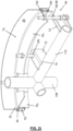
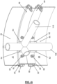
- the enveloping device according to the invention for a cell phone mast contains at least two flexible envelopes which, when installed, are designed in the form of at least a predominant part of a right elliptical cylinder and each have a lower edge area and an upper edge area.
- the enclosing device contains at least one upper mounting device and at least one lower mounting device, which each extend essentially in one plane, can each be attached to the cell tower with a mast-side end of a plurality of fastening elements and ends of the fastening elements facing away from the mast with at least one fastening element respective mounting device are connected, which extends in a circumferential direction of the respective plane at least along a part of the circumference.
- a sum of the extent of all the mounting elements makes up a predominant part of the circumference.
- the at least one retaining element of the upper retaining device is operatively connected to the upper edge area of the flexible cover and the at least one retaining element of the lower retaining device is operatively connected to the lower edge area of the flexible cover.
- a "flexible" cover is to be understood in particular as a cover made of a flat material which, when free-standing in a direction transverse to the surface, can absorb an external force which is only a small fraction, for example less than 1%, of a external force is that of the sheet material in directions that lie within the surface, can be absorbed to a maximum.
- a "straight elliptical cylindrical shape” is to be understood in the sense of the invention in particular as the shape of a cylinder jacket whose central axis is arranged perpendicularly to its base, the base being elliptical and in particular circular.
- operatively connected should be understood in particular to mean that operatively connected objects are connected to one another in such a way that a force can be transmitted between the objects.
- the transmission can take place both through direct contact and indirectly, through at least one intermediate element.
- the term "plurality” is to be understood in particular as meaning a number of at least two.
- a cladding of an antenna support for mobile radio technology is provided, through which effort for the production of molds can be avoided, which can be easily installed and designed and dimensioned in a flexible manner.
- the flexible cover of the cover device can protect the antenna support and any transmission antennas attached thereto from environmental and weather influences.
- the wrapping device can adapt the mobile radio mast to its surroundings and thereby make it less conspicuous.
- the enveloping device has at least two clamping devices, each with a plurality of clamping elements, which are arranged in an operatively connected manner between the holding element or the holding elements and in each case one fastening element of the multiplicity of fastening elements of the lower holding device and are operatively connected to the lower edge region at a multiplicity of positions in the circumferential direction are.
- the tightening members of the plurality of tightening members are operatively connected between the mounting member or members and each one of the plurality of mounting members of the upper mounting assembly and at a plurality of positions in the Circumferentially operatively connected to the upper edge region.
- the at least one flexible casing can be applied uniformly to the respective positions in the circumferential direction with a force that is directed along a generatrix of the straight elliptical cylinder, i.e. parallel to a central axis of the cylinder, so that the flexible casing is turned into a tense state.
- a force that is directed along a generatrix of the straight elliptical cylinder, i.e. parallel to a central axis of the cylinder so that the flexible casing is turned into a tense state.
- the clamping elements of the clamping devices are designed as threaded screw elements which, in the installed state, are in mechanical engagement with a further threaded screw element of one of the mounting elements and a respective threaded screw element of one of the fastening elements.
- the threaded screw elements can be configured as, but not limited to, a threaded screw, a threaded rod, a nut, or a through hole.
Landscapes
- Engineering & Computer Science (AREA)
- Architecture (AREA)
- Life Sciences & Earth Sciences (AREA)
- Chemical & Material Sciences (AREA)
- Materials Engineering (AREA)
- Wood Science & Technology (AREA)
- Civil Engineering (AREA)
- Structural Engineering (AREA)
- Computer Networks & Wireless Communication (AREA)
- Support Of Aerials (AREA)
Claims (8)
- Dispositif d'enveloppement (10) pour un mât de téléphonie mobile (104), comprenant- au moins deux enveloppes flexibles (12, 26) qui sont conçues à l'état monté à chaque fois en forme d'un cylindre elliptique rectiligne avec une surface de section identique, présentent une zone marginale inférieure (18, 32) et une zone marginale supérieure (14, 28) qui, à l'état monté, sont disposées l'une sur l'autre, de façon jointive et d'une manière concentrique, et qui peuvent être placées à chaque fois sur le mât de téléphonie mobile (104) avec un dispositif de support supérieur (40, 60) et un dispositif de support inférieur (52, 70) du dispositif d'enveloppement (10), dans lequel à chaque fois un dispositif de support inférieur (52, 70) qui s'étend à chaque fois essentiellement dans un plan, peut être placé sur le mât de téléphonie mobile (104) à chaque fois par une extrémité côté mât d'une pluralité d'éléments de fixation (42, 54, 62, 72) du dispositif d'enveloppement et des extrémités opposées au mât des éléments de fixation (42, 54, 62, 72) sont reliées à au moins un élément de support (46, 56, 64, 76) du dispositif de support respectif (40, 52, 60, 70), qui s'étend dans un sens circonférentiel du plan respectif au moins le long d'une partie de la circonférence, dans lequel une somme de l'extension de tous les éléments de support (46, 56, 64, 76) représente une partie essentielle de la circonférence et, à l'état monté, le au moins un élément de support (46, 64) de l'élément de support supérieur (40, 60) est relié en liaison active à la zone marginale supérieure (14, 28) de l'enveloppe flexible (12, 26) et le au moins un élément de support (56, 76) du dispositif de support inférieur (52, 70) est relié en liaison active à la zone marginale inférieure (18, 32) de l'enveloppe flexible (12, 26),
caractérisé en ce que- au moins deux dispositifs tendeurs (80, 94) avec à chaque fois une pluralité d'éléments tendeurs (82, 96), dans lequel chacun des au moins deux dispositifs tendeurs (80, 94) est affecté à l'une des au moins deux enveloppes flexibles (12, 26) et les éléments tendeurs (82) du dispositif tendeur respectif (80) pour l'enveloppe flexible disposée tout en haut (12), sont disposés en liaison active entre les éléments de support (56) et à chaque fois un élément de fixation (42, 62) de la pluralité d'éléments de fixation (42) du dispositif de support supérieur (40) et sont en liaison active à une pluralité de positions dans le sens circonférentiel avec la zone marginale supérieure (14),pour l'enveloppe flexible disposée tout en bas (26), sont disposés en liaison active entre l'élément de support (76) et à chaque fois un élément de fixation (72) de la pluralité d'éléments de fixation (72) du dispositif de support inférieur (70) et sont en liaison active à une pluralité de positions dans le sens circonférentiel avec la zone marginale inférieure (32),dans lequel les éléments tendeurs (82, 96) des dispositifs tendeurs (80, 94) sont conçus comme des éléments de boulon fileté qui, à l'état monté, se trouvent en prise mécanique à chaque fois avec un autre élément de boulon fileté d'un des éléments de support (46, 56, 64, 76) et à chaque fois un élément de boulon fileté d'un des éléments de fixation (42, 54, 62, 72). - Dispositif d'enveloppement (10) selon la revendication 1, caractérisé en ce que chaque enveloppe flexible (12, 26) présente au moins un bourrelet (16, 20, 30, 34) qui est disposé dans la zone marginale inférieure (18, 32) ou dans la zone marginale supérieure (14, 28), et en ce que le dispositif de support (40, 52, 60, 70) disposé le plus proche d'au moins un bourrelet (16, 20, 30, 34) comprend à l'état monté un rail de bourrelet (48, 58, 66, 78) pour loger le bourrelet (16, 20, 30, 34), ce par quoi est créée une liaison active entre la zone marginale concernée (14, 18, 28, 32) et l'élément de support (46, 56, 64, 76) du dispositif de support (40, 52, 60, 70) disposé le plus près.
- Dispositif d'enveloppement (10) selon l'une des revendications précédentes, caractérisé en ce que chaque enveloppe flexible (12, 26) présente au moins une fermeture éclair (22, 36) qui est orientée le long de la longueur intégrale d'une génératrice du cylindre elliptique rectiligne et est prévue pour diviser intégralement et d'une manière réversible l'enveloppe flexible (12, 26) le long de la génératrice.
- Dispositif d'enveloppement (10) selon l'une des revendications précédentes, caractérisé en ce que chaque enveloppe flexible (12, 26) présente au moins une ouverture de passage (241, 242, 381, 382) à travers laquelle est créée une liaison fluidique entre un espace interne entouré par l'enveloppe flexible (12, 26) et l'environnement extérieur.
- Dispositif d'enveloppement (10) selon l'une des revendications précédentes, caractérisé en ce que chaque enveloppe flexible (12, 26) présente une surface extérieure qui est prévue pour recevoir l'encre d'impression.
- Dispositif d'enveloppement (10) selon l'une des revendications précédentes, caractérisé en ce que chaque enveloppe flexible (12, 26) présente une part prédominante de polyéther sulfone.
- Dispositif d'enveloppement (10) selon l'une des revendications précédentes, caractérisé en ce que la surface extérieure de chaque enveloppe flexible (12, 26) présente une enduction qui comprend une part prédominante de polychlorure de vinyle.
- Mât de téléphonie mobile (104) pour le montage d'une pluralité d'antennes d'émission de la téléphonie mobile, caractérisé par un dispositif d'enveloppement (10) selon l'une des revendications précédentes qui est agencé sur le mât de téléphonie mobile (104) avec l'extrémité côté mât de la pluralité d'éléments de fixation (42, 54, 62, 72).
Applications Claiming Priority (1)
| Application Number | Priority Date | Filing Date | Title |
|---|---|---|---|
| LU101348A LU101348B1 (de) | 2019-08-12 | 2019-08-12 | Einhüllvorrichtung eines Mobilfunkmastes |
Publications (3)
| Publication Number | Publication Date |
|---|---|
| EP3780262A1 EP3780262A1 (fr) | 2021-02-17 |
| EP3780262C0 EP3780262C0 (fr) | 2023-09-06 |
| EP3780262B1 true EP3780262B1 (fr) | 2023-09-06 |
Family
ID=67766226
Family Applications (1)
| Application Number | Title | Priority Date | Filing Date |
|---|---|---|---|
| EP20189852.5A Active EP3780262B1 (fr) | 2019-08-12 | 2020-08-06 | Dispositif d'enveloppement pour une antenne-relais de téléphonie mobile |
Country Status (4)
| Country | Link |
|---|---|
| EP (1) | EP3780262B1 (fr) |
| ES (1) | ES2964765T3 (fr) |
| LU (1) | LU101348B1 (fr) |
| MA (1) | MA54255A (fr) |
Family Cites Families (4)
| Publication number | Priority date | Publication date | Assignee | Title |
|---|---|---|---|---|
| US20130113680A1 (en) * | 2011-11-08 | 2013-05-09 | STEALTH Concealment Solutions, Inc. | Antenna concealment structures incorporating fabric concealment shells |
| SE536447C2 (sv) * | 2012-03-27 | 2013-11-05 | Induflex AB | Spännanordning för att spänna ut en radomduk |
| GB201304509D0 (en) * | 2013-03-13 | 2013-04-24 | Dynamic Concepts International Ltd | Improved telecommunications apparatus |
| EP3033805B1 (fr) * | 2013-08-16 | 2017-05-24 | CommScope Technologies LLC | Architecture modulaire à petites cellules |
-
2019
- 2019-08-12 LU LU101348A patent/LU101348B1/de active IP Right Grant
-
2020
- 2020-08-06 ES ES20189852T patent/ES2964765T3/es active Active
- 2020-08-06 MA MA054255A patent/MA54255A/fr unknown
- 2020-08-06 EP EP20189852.5A patent/EP3780262B1/fr active Active
Also Published As
| Publication number | Publication date |
|---|---|
| MA54255A (fr) | 2021-09-22 |
| ES2964765T3 (es) | 2024-04-09 |
| EP3780262C0 (fr) | 2023-09-06 |
| LU101348B1 (de) | 2021-02-12 |
| EP3780262A1 (fr) | 2021-02-17 |
Similar Documents
| Publication | Publication Date | Title |
|---|---|---|
| EP1341255B1 (fr) | Module d'antenne et pylone d'éclairage avec un tel module d'antenne | |
| DE69412454T2 (de) | Plattenstruktur für kabine | |
| DE102020124999B4 (de) | Hochdrucktank, Fahrzeug mit einem Hochdrucktank und Verfahren zum Herstellen eines Hochdrucktanks | |
| DE29500055U1 (de) | Haltevorrichtung zum Verankern ein- oder mehrlagiger Bahnen an einem ortsfesten Bauteil | |
| DE102019004829A1 (de) | Stützsystem zum Tragen eines Teils eines Bauwerks | |
| DE102005063234B4 (de) | Tragkonstruktion zum Aufbau von Antennenmasten und dergleichen | |
| EP2602862A1 (fr) | Support d'antennes | |
| DE102013010944A1 (de) | Trägersystem zum Aufbau einer Freilandanlage für Photovoltaikmodule | |
| DE202012104361U1 (de) | Montagesystem für Solarmodule | |
| LU101348B1 (de) | Einhüllvorrichtung eines Mobilfunkmastes | |
| DE3440012A1 (de) | Vorrichtung zur halterung von masten fuer aussenantennen | |
| EP3659685B1 (fr) | Système de bac à sable | |
| DE19717446B4 (de) | Anschlußeinrichtung | |
| DE202010008421U1 (de) | Tragsystem für Solarmodule | |
| EP2211122A1 (fr) | Kit de montage destiné à soutenir des modules solaires | |
| DE202012002547U1 (de) | Vorrichtung zum Abstützen von Solarmodulen | |
| EP1597444A1 (fr) | Procede et dispositif pour rendre etanche le passage de pieces traversant un syteme d isolation thermique | |
| DE20019188U1 (de) | Vorrichtung zur Montage einer Verbundsicherheitsglasplatte | |
| DE3319330A1 (de) | Antennenanlage, insbesondere fuer fuellsender und empfangsstationen | |
| DE202021101571U1 (de) | Einsatzmodul für ein Wandelement und Wandelement mit Einsatzmodul | |
| DE202015106900U1 (de) | Fangmast-Vorrichtung mit Sockel für einen Blitzfangmast | |
| AT503466B1 (de) | Traganordnung für sektorantennen | |
| DE2947956A1 (de) | Sonnenkollektor | |
| DE20200956U1 (de) | Vorrichtung für die Montage von Absturzsicherungseinrichtungen im Dachbereich | |
| DE20002415U1 (de) | Sicherheits-Metallzaun |
Legal Events
| Date | Code | Title | Description |
|---|---|---|---|
| PUAI | Public reference made under article 153(3) epc to a published international application that has entered the european phase |
Free format text: ORIGINAL CODE: 0009012 |
|
| STAA | Information on the status of an ep patent application or granted ep patent |
Free format text: STATUS: THE APPLICATION HAS BEEN PUBLISHED |
|
| AK | Designated contracting states |
Kind code of ref document: A1 Designated state(s): AL AT BE BG CH CY CZ DE DK EE ES FI FR GB GR HR HU IE IS IT LI LT LU LV MC MK MT NL NO PL PT RO RS SE SI SK SM TR |
|
| AX | Request for extension of the european patent |
Extension state: BA ME |
|
| STAA | Information on the status of an ep patent application or granted ep patent |
Free format text: STATUS: REQUEST FOR EXAMINATION WAS MADE |
|
| 17P | Request for examination filed |
Effective date: 20210817 |
|
| RAV | Requested validation state of the european patent: fee paid |
Extension state: TN Effective date: 20210817 Extension state: MA Effective date: 20210817 |
|
| RBV | Designated contracting states (corrected) |
Designated state(s): AL AT BE BG CH CY CZ DE DK EE ES FI FR GB GR HR HU IE IS IT LI LT LU LV MC MK MT NL NO PL PT RO RS SE SI SK SM TR |
|
| GRAP | Despatch of communication of intention to grant a patent |
Free format text: ORIGINAL CODE: EPIDOSNIGR1 |
|
| STAA | Information on the status of an ep patent application or granted ep patent |
Free format text: STATUS: GRANT OF PATENT IS INTENDED |
|
| RIC1 | Information provided on ipc code assigned before grant |
Ipc: H01Q 1/02 20060101ALN20230222BHEP Ipc: E04H 12/10 20060101ALI20230222BHEP Ipc: E04H 12/02 20060101ALI20230222BHEP Ipc: E04H 12/08 20060101ALI20230222BHEP Ipc: H01Q 1/44 20060101ALI20230222BHEP Ipc: H01Q 1/42 20060101ALI20230222BHEP Ipc: H01Q 1/24 20060101ALI20230222BHEP Ipc: H01Q 1/12 20060101AFI20230222BHEP |
|
| RIC1 | Information provided on ipc code assigned before grant |
Ipc: H01Q 1/02 20060101ALN20230307BHEP Ipc: E04H 12/10 20060101ALI20230307BHEP Ipc: E04H 12/02 20060101ALI20230307BHEP Ipc: E04H 12/08 20060101ALI20230307BHEP Ipc: H01Q 1/44 20060101ALI20230307BHEP Ipc: H01Q 1/42 20060101ALI20230307BHEP Ipc: H01Q 1/24 20060101ALI20230307BHEP Ipc: H01Q 1/12 20060101AFI20230307BHEP |
|
| INTG | Intention to grant announced |
Effective date: 20230321 |
|
| GRAS | Grant fee paid |
Free format text: ORIGINAL CODE: EPIDOSNIGR3 |
|
| GRAA | (expected) grant |
Free format text: ORIGINAL CODE: 0009210 |
|
| STAA | Information on the status of an ep patent application or granted ep patent |
Free format text: STATUS: THE PATENT HAS BEEN GRANTED |
|
| AK | Designated contracting states |
Kind code of ref document: B1 Designated state(s): AL AT BE BG CH CY CZ DE DK EE ES FI FR GB GR HR HU IE IS IT LI LT LU LV MC MK MT NL NO PL PT RO RS SE SI SK SM TR |
|
| REG | Reference to a national code |
Ref country code: GB Ref legal event code: FG4D Free format text: NOT ENGLISH |
|
| REG | Reference to a national code |
Ref country code: CH Ref legal event code: EP |
|
| REG | Reference to a national code |
Ref country code: IE Ref legal event code: FG4D Free format text: LANGUAGE OF EP DOCUMENT: GERMAN |
|
| REG | Reference to a national code |
Ref country code: DE Ref legal event code: R096 Ref document number: 502020005092 Country of ref document: DE |
|
| U01 | Request for unitary effect filed |
Effective date: 20230906 |
|
| U07 | Unitary effect registered |
Designated state(s): AT BE BG DE DK EE FI FR IT LT LU LV MT NL PT SE SI Effective date: 20230914 |
|
| PG25 | Lapsed in a contracting state [announced via postgrant information from national office to epo] |
Ref country code: GR Free format text: LAPSE BECAUSE OF FAILURE TO SUBMIT A TRANSLATION OF THE DESCRIPTION OR TO PAY THE FEE WITHIN THE PRESCRIBED TIME-LIMIT Effective date: 20231207 |
|
| PG25 | Lapsed in a contracting state [announced via postgrant information from national office to epo] |
Ref country code: RS Free format text: LAPSE BECAUSE OF FAILURE TO SUBMIT A TRANSLATION OF THE DESCRIPTION OR TO PAY THE FEE WITHIN THE PRESCRIBED TIME-LIMIT Effective date: 20230906 Ref country code: NO Free format text: LAPSE BECAUSE OF FAILURE TO SUBMIT A TRANSLATION OF THE DESCRIPTION OR TO PAY THE FEE WITHIN THE PRESCRIBED TIME-LIMIT Effective date: 20231206 Ref country code: HR Free format text: LAPSE BECAUSE OF FAILURE TO SUBMIT A TRANSLATION OF THE DESCRIPTION OR TO PAY THE FEE WITHIN THE PRESCRIBED TIME-LIMIT Effective date: 20230906 Ref country code: GR Free format text: LAPSE BECAUSE OF FAILURE TO SUBMIT A TRANSLATION OF THE DESCRIPTION OR TO PAY THE FEE WITHIN THE PRESCRIBED TIME-LIMIT Effective date: 20231207 |
|
| PG25 | Lapsed in a contracting state [announced via postgrant information from national office to epo] |
Ref country code: IS Free format text: LAPSE BECAUSE OF FAILURE TO SUBMIT A TRANSLATION OF THE DESCRIPTION OR TO PAY THE FEE WITHIN THE PRESCRIBED TIME-LIMIT Effective date: 20240106 |
|
| REG | Reference to a national code |
Ref country code: ES Ref legal event code: FG2A Ref document number: 2964765 Country of ref document: ES Kind code of ref document: T3 Effective date: 20240409 |
|
| PG25 | Lapsed in a contracting state [announced via postgrant information from national office to epo] |
Ref country code: SM Free format text: LAPSE BECAUSE OF FAILURE TO SUBMIT A TRANSLATION OF THE DESCRIPTION OR TO PAY THE FEE WITHIN THE PRESCRIBED TIME-LIMIT Effective date: 20230906 Ref country code: RO Free format text: LAPSE BECAUSE OF FAILURE TO SUBMIT A TRANSLATION OF THE DESCRIPTION OR TO PAY THE FEE WITHIN THE PRESCRIBED TIME-LIMIT Effective date: 20230906 Ref country code: IS Free format text: LAPSE BECAUSE OF FAILURE TO SUBMIT A TRANSLATION OF THE DESCRIPTION OR TO PAY THE FEE WITHIN THE PRESCRIBED TIME-LIMIT Effective date: 20240106 Ref country code: CZ Free format text: LAPSE BECAUSE OF FAILURE TO SUBMIT A TRANSLATION OF THE DESCRIPTION OR TO PAY THE FEE WITHIN THE PRESCRIBED TIME-LIMIT Effective date: 20230906 Ref country code: SK Free format text: LAPSE BECAUSE OF FAILURE TO SUBMIT A TRANSLATION OF THE DESCRIPTION OR TO PAY THE FEE WITHIN THE PRESCRIBED TIME-LIMIT Effective date: 20230906 |
|
| PG25 | Lapsed in a contracting state [announced via postgrant information from national office to epo] |
Ref country code: PL Free format text: LAPSE BECAUSE OF FAILURE TO SUBMIT A TRANSLATION OF THE DESCRIPTION OR TO PAY THE FEE WITHIN THE PRESCRIBED TIME-LIMIT Effective date: 20230906 |
|
| REG | Reference to a national code |
Ref country code: DE Ref legal event code: R097 Ref document number: 502020005092 Country of ref document: DE |
|
| PLBE | No opposition filed within time limit |
Free format text: ORIGINAL CODE: 0009261 |
|
| STAA | Information on the status of an ep patent application or granted ep patent |
Free format text: STATUS: NO OPPOSITION FILED WITHIN TIME LIMIT |
|
| U20 | Renewal fee for the european patent with unitary effect paid |
Year of fee payment: 5 Effective date: 20240614 |
|
| 26N | No opposition filed |
Effective date: 20240607 |
|
| PG25 | Lapsed in a contracting state [announced via postgrant information from national office to epo] |
Ref country code: MC Free format text: LAPSE BECAUSE OF FAILURE TO SUBMIT A TRANSLATION OF THE DESCRIPTION OR TO PAY THE FEE WITHIN THE PRESCRIBED TIME-LIMIT Effective date: 20230906 |
|
| PGFP | Annual fee paid to national office [announced via postgrant information from national office to epo] |
Ref country code: GB Payment date: 20250617 Year of fee payment: 6 |
|
| U20 | Renewal fee for the european patent with unitary effect paid |
Year of fee payment: 6 Effective date: 20250616 |
|
| PG25 | Lapsed in a contracting state [announced via postgrant information from national office to epo] |
Ref country code: IE Free format text: LAPSE BECAUSE OF NON-PAYMENT OF DUE FEES Effective date: 20240806 |
|
| PGFP | Annual fee paid to national office [announced via postgrant information from national office to epo] |
Ref country code: ES Payment date: 20250917 Year of fee payment: 6 |
|
| PGFP | Annual fee paid to national office [announced via postgrant information from national office to epo] |
Ref country code: CH Payment date: 20250901 Year of fee payment: 6 |
|
| PG25 | Lapsed in a contracting state [announced via postgrant information from national office to epo] |
Ref country code: CY Free format text: LAPSE BECAUSE OF FAILURE TO SUBMIT A TRANSLATION OF THE DESCRIPTION OR TO PAY THE FEE WITHIN THE PRESCRIBED TIME-LIMIT; INVALID AB INITIO Effective date: 20200806 |
|
| VS25 | Lapsed in a validation state [announced via postgrant information from nat. office to epo] |
Ref country code: MA Free format text: FAILURE TO ELECT DOMICILE IN THE NATIONAL COUNTRY Effective date: 20231207 |
|
| PG25 | Lapsed in a contracting state [announced via postgrant information from national office to epo] |
Ref country code: HU Free format text: LAPSE BECAUSE OF FAILURE TO SUBMIT A TRANSLATION OF THE DESCRIPTION OR TO PAY THE FEE WITHIN THE PRESCRIBED TIME-LIMIT; INVALID AB INITIO Effective date: 20200806 |
|
| VS25 | Lapsed in a validation state [announced via postgrant information from nat. office to epo] |
Ref country code: MA Free format text: LAPSE BECAUSE OF FAILURE TO SUBMIT A TRANSLATION OF THE DESCRIPTION OR TO PAY THE FEE WITHIN THE PRESCRIBED TIME-LIMIT Effective date: 20230906 |