EP3780276A1 - Procédé et dispositif de mesure - Google Patents
Procédé et dispositif de mesure Download PDFInfo
- Publication number
- EP3780276A1 EP3780276A1 EP19826770.0A EP19826770A EP3780276A1 EP 3780276 A1 EP3780276 A1 EP 3780276A1 EP 19826770 A EP19826770 A EP 19826770A EP 3780276 A1 EP3780276 A1 EP 3780276A1
- Authority
- EP
- European Patent Office
- Prior art keywords
- antenna group
- antenna
- electromagnetic wave
- wave transmitted
- measurement probe
- Prior art date
- Legal status (The legal status is an assumption and is not a legal conclusion. Google has not performed a legal analysis and makes no representation as to the accuracy of the status listed.)
- Granted
Links
Images




Classifications
-
- G—PHYSICS
- G01—MEASURING; TESTING
- G01R—MEASURING ELECTRIC VARIABLES; MEASURING MAGNETIC VARIABLES
- G01R29/00—Arrangements for measuring or indicating electric quantities not covered by groups G01R19/00 - G01R27/00
- G01R29/08—Measuring electromagnetic field characteristics
- G01R29/0864—Measuring electromagnetic field characteristics characterised by constructional or functional features
- G01R29/0892—Details related to signal analysis or treatment; presenting results, e.g. displays; measuring specific signal features other than field strength, e.g. polarisation, field modes, phase, envelope, maximum value
-
- G—PHYSICS
- G01—MEASURING; TESTING
- G01R—MEASURING ELECTRIC VARIABLES; MEASURING MAGNETIC VARIABLES
- G01R29/00—Arrangements for measuring or indicating electric quantities not covered by groups G01R19/00 - G01R27/00
- G01R29/08—Measuring electromagnetic field characteristics
- G01R29/10—Radiation diagrams of antennas
-
- H—ELECTRICITY
- H01—ELECTRIC ELEMENTS
- H01Q—ANTENNAS, i.e. RADIO AERIALS
- H01Q21/00—Antenna arrays or systems
-
- H—ELECTRICITY
- H01—ELECTRIC ELEMENTS
- H01Q—ANTENNAS, i.e. RADIO AERIALS
- H01Q3/00—Arrangements for changing or varying the orientation or the shape of the directional pattern of the waves radiated from an antenna or antenna system
- H01Q3/26—Arrangements for changing or varying the orientation or the shape of the directional pattern of the waves radiated from an antenna or antenna system varying the relative phase or relative amplitude of energisation between two or more active radiating elements; varying the distribution of energy across a radiating aperture
- H01Q3/267—Phased-array testing or checking devices
-
- H—ELECTRICITY
- H01—ELECTRIC ELEMENTS
- H01Q—ANTENNAS, i.e. RADIO AERIALS
- H01Q3/00—Arrangements for changing or varying the orientation or the shape of the directional pattern of the waves radiated from an antenna or antenna system
- H01Q3/26—Arrangements for changing or varying the orientation or the shape of the directional pattern of the waves radiated from an antenna or antenna system varying the relative phase or relative amplitude of energisation between two or more active radiating elements; varying the distribution of energy across a radiating aperture
- H01Q3/28—Arrangements for changing or varying the orientation or the shape of the directional pattern of the waves radiated from an antenna or antenna system varying the relative phase or relative amplitude of energisation between two or more active radiating elements; varying the distribution of energy across a radiating aperture varying the amplitude
-
- H—ELECTRICITY
- H01—ELECTRIC ELEMENTS
- H01Q—ANTENNAS, i.e. RADIO AERIALS
- H01Q3/00—Arrangements for changing or varying the orientation or the shape of the directional pattern of the waves radiated from an antenna or antenna system
- H01Q3/26—Arrangements for changing or varying the orientation or the shape of the directional pattern of the waves radiated from an antenna or antenna system varying the relative phase or relative amplitude of energisation between two or more active radiating elements; varying the distribution of energy across a radiating aperture
- H01Q3/30—Arrangements for changing or varying the orientation or the shape of the directional pattern of the waves radiated from an antenna or antenna system varying the relative phase or relative amplitude of energisation between two or more active radiating elements; varying the distribution of energy across a radiating aperture varying the relative phase between the radiating elements of an array
- H01Q3/34—Arrangements for changing or varying the orientation or the shape of the directional pattern of the waves radiated from an antenna or antenna system varying the relative phase or relative amplitude of energisation between two or more active radiating elements; varying the distribution of energy across a radiating aperture varying the relative phase between the radiating elements of an array by electrical means
-
- H—ELECTRICITY
- H04—ELECTRIC COMMUNICATION TECHNIQUE
- H04B—TRANSMISSION
- H04B17/00—Monitoring; Testing
- H04B17/10—Monitoring; Testing of transmitters
- H04B17/11—Monitoring; Testing of transmitters for calibration
- H04B17/12—Monitoring; Testing of transmitters for calibration of transmit antennas, e.g. of the amplitude or phase
Definitions
- Embodiments of this application relate to the communications field, and in particular, to a measurement method and a device.
- a massive multiple-input multiple-output (Massive Multiple-input and Multiple-output, Massive MIMO) technology based on a phased array antenna is widely used in a 5G communications system.
- a network device and a terminal device each may be an antenna array including a plurality of antenna units that are independently controllable in phase (or delay) and that are arranged based on a specific spatial layout.
- an over-the-air (Over the Air, OTA) beam indicator of a network device or a terminal device may be measured by using an over-the-air measurement technology.
- an OTA measurement system is deployed in a darkroom to obtain the over-the-air beam indicator of the network device or the terminal device.
- the OTA measurement system includes a measurement probe and a measured device (the network device or the terminal device).
- an over-the-air beam indicator of the device is usually measured in a far field, that is, a distance between the measurement probe and the measured device is relatively long. Consequently, the OTA measurement system occupies relatively large space, and is not suitable for large-scale deployment and use in production.
- a spherical wave emitted by the measured device may be converted into a plane wave through a collimating component within a short distance, to meet a far-field measurement requirement.
- the collimating component needs to be processed with high precision, leading to complex mounting and maintenance and high costs.
- Embodiments of this application provide a measurement method and a device, to reduce measurement costs while achieving an equivalent far-field measurement effect within a short distance by using a small-sized measurement system, helping deploy the measurement system widely.
- a measurement method is disclosed, where the method is applied to an over-the-air measurement system, the over-the-air measurement system includes a second device and a first device, the first device includes an antenna array, the antenna array includes at least one antenna group, and the second device includes a measurement probe, where a distance between the first device and the measurement probe is less than a far-field boundary distance.
- the method includes: for each antenna group other than a target antenna group in the antenna array, determining compensation values of the antenna group based on characteristic parameters of the antenna group and characteristic parameters of the target antenna group, where the compensation values include a phase compensation value and an amplitude compensation value, the characteristic parameters include a first characteristic parameter and a second characteristic parameter, the first characteristic parameter is used to determine a phase compensation value, and the second characteristic parameter is used to determine an amplitude compensation value; and further, adjusting, based on the compensation values of the antenna group, an electromagnetic wave transmitted by each antenna unit in the antenna group, so that electromagnetic waves transmitted by all antenna units in the antenna array have a same phase and/or amplitude when the electromagnetic waves arrive at the measurement probe, and are coherently superposed.
- the second device may measure an electromagnetic wave transmitted by the first device, to obtain an over-the-air beam parameter of the first device.
- electromagnetic waves transmitted by all antennas of the first device have aligned amplitudes and phases on the measurement probe, and are coherently superposed, thereby achieving equivalent far-field alignment and superposition of the amplitudes and the phases of the electromagnetic waves transmitted by all the antennas. That is, in this embodiment of the present invention, measurement costs can be reduced while an equivalent far-field measurement effect can be achieved within a short distance by using a small-sized measurement system, helping deploy the measurement system widely.
- electromagnetic waves transmitted by a to-be-measured device are coherently superposed at a measurement probe, and amplitudes of the electromagnetic waves are amplified, so that a more accurate measurement result can be obtained. It can be learned that the method provided in this embodiment of the present invention can achieve a far-field measurement effect in a medium or near field, and obtain a highly accurate measurement result.
- the determining compensation values of the antenna group based on characteristic parameters of the antenna group and characteristic parameters of the target antenna group specifically includes: using a distance from a center point of the antenna group to the measurement probe as the first characteristic parameter of the antenna group, calculating a distance difference between the first characteristic parameter of the antenna group and the first characteristic parameter of the target antenna group in the antenna array, and calculating the phase compensation value of the antenna group based on the distance difference of the antenna group; and using an azimuth and a pitch angle between a normal line of the measurement probe and a connection line between the center point of the antenna group and a center point of the measurement probe as the second characteristic parameter of the antenna group, obtaining a gain decrement of the antenna group based on the azimuth corresponding to the antenna group, obtaining a gain decrement of the measurement probe based on the pitch angle corresponding to the antenna group, and using a sum of the gain decrement of the antenna group and the gain decrement of the measurement probe as
- the phase compensation value of the antenna group may be calculated based on the distance between the antenna group and the measurement probe, to make phase compensation for an electromagnetic wave transmitted by the antenna group, and the amplitude compensation value of the antenna group may be calculated based on an angle between the antenna group and the measurement probe, to make amplitude compensation for the electromagnetic wave transmitted by the antenna group.
- a required compensation phase may be accurately calculated according to the foregoing calculation formula, to provide a basis for subsequent phase adjustment, and ensure, to some extent, that electromagnetic waves transmitted by the first device are coherently superposed when arriving at the measurement probe.
- the first device determines, based on the characteristic parameters of each antenna group in the antenna array, the compensation values corresponding to each antenna group in the antenna array specifically includes: the determining compensation values of the antenna group based on characteristic parameters of the antenna group and characteristic parameters of the target antenna group specifically includes: first, transmitting an electromagnetic wave by using each antenna group in the antenna array, and then, obtaining an amplitude and a phase, of the electromagnetic wave transmitted by each antenna group, that exist when the electromagnetic wave transmitted by each antenna group arrives at the measurement probe; calculating a phase difference between the phase, of the electromagnetic wave transmitted by the antenna group, that exists when the electromagnetic wave transmitted by the antenna group arrives at the measurement probe and the phase, of the electromagnetic wave transmitted by the target antenna group, that exists when the electromagnetic wave transmitted by the target antenna group arrives at the measurement probe, and using the phase difference as the phase compensation value of the antenna group, where the phase, of the electromagnetic wave transmitted by the antenna group, that exists when the electromagnetic wave transmitted by the antenna group arrives at the
- amplitude and phase values that are of the antenna groups and that are obtained when electromagnetic waves transmitted by the antenna groups arrive at the measurement probe may also be measured one by one, to obtain an amplitude difference and a phase difference of each antenna group.
- a specified amplitude compensation value needs to be used to compensate for the amplitude difference obtained herein, and a specified phase compensation value needs to be used to compensate for the phase difference obtained herein, to ensure that amplitudes and phases of signals of the antenna groups are aligned at the measurement probe.
- the method further includes: adjusting, based on the compensation values corresponding to the antenna group, an electromagnetic wave received by each antenna unit in the antenna group, so that electromagnetic waves received by all the antenna units in the antenna array have a same phase and/or amplitude; and measuring the over-the-air beam parameter of the first device based on a signal received by each antenna unit in the antenna array.
- an electromagnetic wave transmitted by the measurement probe may be further measured, to obtain an over-the-air beam parameter of the second device.
- the over-the-air beam parameter in this embodiment of the present invention includes at least one of an effective isotropically radiated power EIRP, an error vector magnitude EVM, an adjacent channel leakage ratio ACLR, a frequency error, and effective isotropic sensitivity EIS.
- a device is disclosed, where the device is a first device, the first device belongs to an over-the-air measurement system, the over-the-air measurement system further includes a second device, the first device includes an antenna array, the antenna array includes at least one antenna group, the second device includes a measurement probe, a distance between the first device and the measurement probe is less than a far-field boundary distance, and the first device includes: a processing module, configured to: for each antenna group other than a target antenna group in the antenna array, obtain characteristic parameters of the antenna group and characteristic parameters of the target antenna group; and determine compensation values of the antenna group based on the characteristic parameters of the antenna group and the characteristic parameters of the target antenna group, where the compensation values include a phase compensation value and an amplitude compensation value, the characteristic parameters include a first characteristic parameter and a second characteristic parameter, the first characteristic parameter is used to determine a phase compensation value, and the second characteristic parameter is used to determine an amplitude compensation value, where the processing module is further configured to adjust, based on the compensation values of
- electromagnetic waves transmitted by all antennas of the first device have aligned amplitudes and phases on the measurement probe, and are coherently superposed, thereby achieving equivalent far-field alignment and superposition of the amplitudes and the phases of the electromagnetic waves transmitted by all the antennas. That is, in this embodiment of the present invention, measurement costs can be reduced while an equivalent far-field measurement effect can be achieved within a short distance by using a small-sized measurement system, helping deploy the measurement system widely.
- electromagnetic waves transmitted by a measured device are coherently superposed at a measurement probe, and amplitudes of the electromagnetic waves are amplified, so that a more accurate measurement result can be obtained. It can be learned that the method provided in this embodiment of the present invention can achieve a far-field measurement effect in a medium or near field, and obtain a highly accurate measurement result.
- the processing module is specifically configured to: use a distance from a center point of the antenna group to the measurement probe as the first characteristic parameter of the antenna group, calculate a distance difference between the first characteristic parameter of the antenna group and the first characteristic parameter of the target antenna group in the antenna array, and calculate the phase compensation value of the antenna group based on the distance difference of the antenna group; and use an azimuth and a pitch angle between a normal line of the measurement probe and a connection line between the center point of the antenna group and a center point of the measurement probe as the second characteristic parameter of the antenna group, obtain a gain decrement of the antenna group based on the azimuth corresponding to the antenna group, obtain a gain decrement of the measurement probe based on the pitch angle corresponding to the antenna group, and use a sum of the gain decrement of the antenna group and the gain decrement of the measurement probe as the amplitude compensation value of the antenna group.
- the processing module is specifically configured to: obtain an amplitude and a phase, of an electromagnetic wave transmitted by each antenna group in the antenna array, that exist when the electromagnetic wave transmitted by each antenna group arrives at the measurement probe; calculate a phase difference between the phase, of the electromagnetic wave transmitted by the antenna group, that exists when the electromagnetic wave transmitted by the antenna group arrives at the measurement probe and the phase, of the electromagnetic wave transmitted by the target antenna group, that exists when the electromagnetic wave transmitted by the target antenna group arrives at the measurement probe, and use the phase difference as the phase compensation value of the antenna group, where the phase, of the electromagnetic wave transmitted by the antenna group, that exists when the electromagnetic wave transmitted by the antenna group arrives at the measurement probe is the first characteristic parameter of the antenna group, and the phase, of the electromagnetic wave transmitted by the target antenna group, that exists when the electromagnetic wave transmitted by the target antenna group arrives at the measurement probe is the first characteristic parameter of the target antenna; and calculate an amplitude difference between the amplitude, of the electromagnetic wave transmitted by the antenna group,
- the processing module is further configured to: adjust, based on the compensation values corresponding to the antenna group, an electromagnetic wave received by each antenna unit in the antenna group, so that electromagnetic waves received by all the antenna units in the antenna array have a same phase and/or amplitude; and measure an over-the-air beam parameter of the first device based on a signal received by each antenna unit in the antenna array.
- the over-the-air beam parameter includes at least one of an effective isotropically radiated power EIRP, an error vector magnitude EVM, an adjacent channel leakage ratio ACLR, a frequency error, and effective isotropic sensitivity EIS.
- An embodiment of the present invention provides an over-the-air measurement system that can measure, within a medium or near field distance, an over-the-air beam parameter of an electromagnetic wave transmitted by a device.
- the over-the-air measurement system includes a first device 10, a second device 20, and a system controller 30.
- the second device 20 may measure, at an over-the-air, an electromagnetic wave transmitted by the first device 10, to obtain an over-the-air beam parameter of the electromagnetic wave transmitted by the first device 10.
- the system controller 30 may control the first device 10 and the second device 20, to complete an entire measurement procedure.
- the first device 10 is an active antenna product, and includes an antenna array 101, an amplitude and phase adjustment module 102, and a calculation module 103.
- the amplitude and phase adjustment module 102 and the calculation module 103 may be collectively referred to as a processing module.
- the antenna array includes antenna units arranged in a matrix form, and the antenna units may be phased array antennas.
- one or more antenna units constitute one antenna group.
- the calculation module 103 is connected to all amplitude and phase adjustment modules 102.
- One amplitude and phase adjustment module 102 is connected to one antenna group, and is configured to adjust an amplitude and a phase of an electromagnetic wave transmitted by the antenna group.
- the calculation module 103 is configured to calculate an amplitude compensation value and/or a phase compensation value of each antenna group, and then send the amplitude compensation value and/or the phase compensation value of the antenna group to the amplitude and phase adjustment module 102 connected to the antenna group.
- the amplitude and phase adjustment module 102 separately adjusts amplitudes and phases of electromagnetic waves transmitted by a plurality of antennas in the antenna group connected to the amplitude and phase adjustment module 102, and performs superposition after the adjustment, to obtain a final transmitted signal.
- one antenna group may include two antennas.
- each amplitude and phase adjustment module 102 is connected to the system controller 103 by using a control interface.
- the second device 20 includes a measurement probe 201 and a data processing module 202.
- the measurement probe 201 is configured to receive the electromagnetic wave transmitted by the first device.
- the data processing module 202 is configured to obtain, based on the received electromagnetic wave, an over-the-air beam parameter, for example, an effective isotropically radiated power (Effective Isotropically Radiated Power, EIRP), an error vector magnitude (Error Vector Magnitude, EVM), an adjacent channel leakage ratio (Adjacent Channel Leakage Ratio, ACLR), a frequency error, effective isotropic sensitivity (Effective Isotropic Sensitivity, EIS), or the like.
- EIRP effective isotropically Radiated Power
- EVM error vector magnitude
- ACLR adjacent channel leakage ratio
- EIS effective isotropic Sensitivity
- the calculation module 103 calculates an amplitude and a phase of each antenna group
- the amplitude and phase adjustment module 102 may include an analog attenuator and a phase shifter.
- the amplitude and phase adjustment module 102 adjusts, in an analog domain by using the attenuator and the phase shifter, an amplitude and a phase of the transmitted electromagnetic wave.
- the amplitude and phase adjustment module 102 may alternatively directly adjust an amplitude and a phase in a digital manner. That is, when transmitting an electromagnetic wave, the first device 20 performs amplitude and phase adjustment in a digital domain, and then the electromagnetic wave enters a digital-to-analog converter (Digital to analog converter, DAC) and changes into an analog signal.
- Digital to analog converter Digital to analog converter
- amplitude and phase adjustment module 102 may alternatively implement amplitude and phase adjustment in a manner mixing analog and digital. This is not limited in this embodiment of the present invention.
- the data processing unit 202 may be a measurement instrument, such as a spectrum analyzer, a power meter, a signal generator, or a radio communication tester. It should be noted that, if an antenna of the first device is an active antenna, the amplitude and phase adjustment module 102 may be built in the first device. If an antenna of the first device is a passive antenna, the amplitude and phase adjustment module 102 needs to be disposed outside the first device.
- An embodiment of the present invention provides a measurement method, applied to the over-the-air measurement system shown in FIG. 1 , and capable of measuring, over the air, an electromagnetic wave transmitted by a device within a medium or near field measurement distance.
- the measured device that is, the first device in the embodiments of the present invention
- measurement costs can be reduced while an equivalent far-field measurement effect can be achieved within a short distance by using a small-sized measurement system, helping deploy the measurement system widely.
- electromagnetic waves transmitted by a measured device are coherently superposed at a measurement probe, and amplitudes of the electromagnetic waves are amplified, so that a more accurate measurement result can be obtained. It can be learned that the method provided in this embodiment of the present invention can achieve a far-field measurement effect in a medium or near field, and obtain a highly accurate measurement result.
- An embodiment of the present invention provides a measurement method, applied to an over-the-air measurement system. As shown in FIG. 4 , the method includes the following steps.
- the calculation module 103 of the first device may determine the compensation values of each antenna group.
- the characteristic parameters of the antenna group include a first characteristic parameter and a second characteristic parameter.
- the first characteristic parameter is used to determine a phase compensation value
- the second characteristic parameter is used to determine an amplitude compensation value.
- a distance between the first device and the measurement probe is less than a far-field boundary distance.
- antennas of the first device are phased array antennas arranged in a matrix form.
- the antenna array of the first device includes phased array antennas in N rows by M columns, each plurality of antennas in each column constitute one antenna group, and each independent antenna may be one antenna group.
- the first characteristic parameter of the antenna group may be a distance between a center of the antenna group and a center of the measurement probe.
- the center of the antenna group is a phase center of the antenna group.
- the phase center of the antenna group coincides with a geometric center.
- an offset between the phase center and the geometric center may be obtained through measurement or simulation, and then the phase center is obtained through derivation based on the geometric center.
- a three-dimensional coordinate system may be created, and the first device and the second device are deployed based on a near field measurement requirement, so that three-dimensional coordinates of each antenna unit and three-dimensional coordinates of the measurement probe may be obtained, and coordinates of a geometric center of an antenna group may be determined by using coordinates of all antenna units in the antenna group.
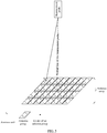
- every two antennas in a column in the matrix constitute one antenna group, a center of the antenna group is a center point A of a straight line in which the two antennas are located, and a first characteristic parameter of the antenna group may be a distance from the center point A to the center of the measurement probe.
- a second characteristic parameter of the antenna group may be an angle between a normal line P of the measurement probe and a connection line L between the center of the antenna group and the center of the measurement probe.
- the angle between the normal line P of the measurement probe and the connection line L between the center of the antenna group and the center of the measurement probe may be classified into an azimuth ⁇ and a pitch angle ⁇ .
- the azimuth between the normal line P of the measurement probe and the connection line L between the center of the antenna group and the center of the measurement probe is an angle between a projection of the connection line L on a horizontal plane and the normal line P of the measurement probe.
- the pitch angle between the normal line P of the measurement probe and the line L between the center of the antenna group and the center of the measurement probe is an angle between a projection of the line L on a vertical plane and the normal line P of the measurement probe.
- a phase compensation value of the antenna group may be obtained based on the first characteristic parameter of the antenna group and a first characteristic parameter of a target antenna group. Specifically, a phase compensation value of each antenna group may be calculated based on a distance from a center of each antenna group to the center of the measurement probe. First, a distance between a center point of each antenna group and a center point of the measurement probe needs to be determined, and an antenna group is selected from all the antenna groups as the target antenna group.
- an antenna group located at a central location of the antenna array of the first device is used as the target antenna group. Further, a distance difference between the characteristic parameters of each antenna group other than the target antenna group in the antenna groups in the antenna array and the characteristic parameters of the target antenna group is calculated. For example, there are six antenna groups A, B, C, D, E, and F in total, distances between the six antenna groups and the center of the measurement probe are respectively S1, S2, S3, S4, S5, and S6, and the antenna group D is designated as the target antenna group.
- the phase compensation value of each antenna group may be calculated based on a distance difference corresponding to each antenna group.
- a wave path difference between antenna groups is calculated by using a distance between the target antenna group and the measurement probe as a reference, so that a phase adjustment value of each antenna group can be determined, and an electromagnetic wave transmitted by each antenna group is adjusted based on the determined phase adjustment value.
- phases of the electromagnetic waves transmitted by the antenna groups are aligned when the electromagnetic waves transmitted by the antenna groups arrive at the measurement probe, so that the electromagnetic waves transmitted by the antenna groups are coherently superposed.
- the second characteristic parameter of the antenna group may be an angle between a normal line P of the measurement probe and a connection line L between the center of the antenna group to the center of the measurement probe, for example, an azimuth angle or a pitch angle.
- the second characteristic parameter of the antenna group indicates a distance between the antenna group and the measurement probe.
- the amplitude compensation value of the antenna group may be obtained based on the second characteristic parameter of the antenna group and a second characteristic parameter of the target antenna group. Specifically, the amplitude compensation value of the antenna group is calculated based on an angle between the normal line P of the measurement probe and the connection line L between the center of the antenna group and the center of the measurement probe.
- an azimuth and a pitch angle between the normal line of the measurement probe and the connection line between the center point of each antenna group and the center point of the measurement probe need to be determined. Further, a gain decrement corresponding to the azimuth of the antenna group and a gain decrement corresponding to the pitch angle of the antenna group may be obtained by comparing directivity patterns of the antenna group. A sum of the two gain decrements is a gain decrement ⁇ 1 of the antenna group.
- the gain decrement of the antenna group may be considered as a transmit gain loss of an antenna caused by an angle between the measurement probe and a direction of the antenna and a main beam.
- the directivity pattern of the antenna group records a correspondence between an angle of an antenna and a transmit gain loss
- the transmit gain loss may be determined by comparing a determined angle of the antenna with the directivity pattern of the antenna group.
- the directivity pattern of the measurement probe records a correspondence between an angle of an antenna and a receive gain loss
- the receive gain loss may be determined by comparing a determined angle of the antenna with the directivity pattern of the measurement probe.
- the first device may further first measure an amplitude and a phase of each antenna group and that are obtained when an electromagnetic wave transmitted by the antenna group arrives at the measurement probe, and then may obtain a phase compensation value and an amplitude compensation value of each antenna group based on a measurement result.
- the first characteristic parameter of the antenna group is a phase, of an electromagnetic wave transmitted by the antenna group, that exists when the electromagnetic wave transmitted by the antenna group arrives at the measurement probe
- the second characteristic parameter of the antenna group is an amplitude, of the electromagnetic wave transmitted by the antenna group, that exists when the electromagnetic wave transmitted by the antenna group arrives at the measurement probe.
- a phase compensation value of an antenna group may be obtained based on the first characteristic parameter of the antenna group and the first characteristic parameter of the target antenna group
- an amplitude compensation value of the antenna group may be obtained based on a second characteristic parameter of the antenna group and the second characteristic parameter of the target antenna group.
- the first device first transmits an electromagnetic wave by using each antenna group, and measures an amplitude and a phase of the electromagnetic wave transmitted by each antenna group that are obtained when the electromagnetic wave transmitted by each antenna group arrives at the measurement probe.
- an antenna group is selected from all antenna groups as the target antenna group. For example, an antenna group located at a central location of the antenna array of the first device is used as the target antenna group.
- an amplitude difference between each antenna group other than the target antenna group in the antenna groups in the antenna array and the target antenna group is calculated as the amplitude compensation value; and a phase difference between each antenna group other than the target antenna group in the antenna groups of the antenna array and the target antenna group is calculated as the phase compensation value.
- phase compensation values of A, B, C, E, and F are respectively ( ⁇ 1 - ⁇ 4 ), ( ⁇ 2 - ⁇ 4 ), ( ⁇ 3 - ⁇ 4 ), ( ⁇ 5 - ⁇ 4 ), and ( ⁇ 6 - ⁇ 4 ).
- Phases of the six antenna groups when the electromagnetic waves transmitted by the six antenna groups arrive at the measurement probe are respectively A1, A2, A3, A4, A5, and A6, and phase compensation values of A, B, C, E, and F are respectively (A1-A4), (A2-A4), (A3-A4), (A5-A4), and (A6-A4).
- the first device sends a control signal to the amplitude and phase adjustment module 102 connected to each antenna group, to indicate an amplitude compensation value and/or a phase compensation value corresponding to the antenna group connected to the amplitude and phase adjustment module 102.
- the amplitude and phase adjustment module 102 may correspondingly adjust, based on an indication of a processor of the first device, an amplitude and a phase of an electromagnetic wave transmitted by the antenna group connected to the amplitude and phase adjustment module 102.
- the amplitude and phase adjustment module 102 may include a phase shifter, and adjust, by using the phase shifter, the phase of the electromagnetic wave transmitted by the antenna group.
- the amplitude and phase adjustment module 102 may further include an attenuator, and adjust, by using the attenuator, the amplitude of the electromagnetic wave transmitted by the antenna group. If the amplitude compensation value is positive, the amplitude of the electromagnetic wave transmitted by the antenna group is increased. If the amplitude compensation value is negative, the amplitude of the electromagnetic wave transmitted by the antenna group is decreased. Certainly, the amplitude and phase adjustment module 102 may alternatively not include any hardware component, and may adjust, in a digital manner, the amplitude and the phase of the electromagnetic wave transmitted by the antenna group. When the antenna group includes a plurality of antennas, the amplitude and phase adjustment module 102 may separately adjust the electromagnetic wave transmitted by each antenna unit, and then weight electromagnetic waves obtained after the adjustment to obtain the electromagnetic wave of the antenna group.
- the first device may not adjust the electromagnetic wave transmitted by the target antenna group, but adjust, based on the amplitude compensation value corresponding to the antenna group, the amplitude of the electromagnetic wave transmitted by the antenna group, and adjust, based on the phase compensation value corresponding to the antenna group, the phase of the electromagnetic wave transmitted by the antenna group.
- electromagnetic waves transmitted by all antenna groups have aligned phases and/or amplitudes when the electromagnetic waves transmitted by all the antenna groups arrive at the measurement probe, achieving equivalent far-field alignment and superposition of the amplitudes and the phases of the electromagnetic waves transmitted by all the antennas.
- adjusting the electromagnetic wave transmitted by the antenna array of the first device may be understood as adjusting an amplitude and a phase of an electrical signal converted from the electromagnetic wave, so that electromagnetic waves can have spatially aligned phases and amplitudes, and are coherently superposed.
- the second device receives, by using the measurement probe, the electromagnetic wave transmitted by the first device, and measures the received electromagnetic wave, to obtain the over-the-air beam parameter of the first device.
- the over-the-air beam parameter obtained by the second device by measuring the received electromagnetic wave may be at least one of an effective isotropically radiated power (Effective Isotropically Radiated Power, EIRP), an error vector magnitude (Error Vector Magnitude, EVM), an adjacent channel leakage ratio (Adjacent Channel Leakage Ratio, ACLR), a frequency error, and effective isotropic sensitivity (Effective Isotropic Sensitivity, EIS).
- EIRP effective isotropically Radiated Power
- EVM error vector magnitude
- ACLR adjacent Channel Leakage Ratio
- ACLR adjacent Channel Leakage Ratio
- EIS effective isotropic Sensitivity
- a distance between the first device and the measurement probe of the second device in the measurement system is less than the far-field boundary distance.
- the amplitudes and the phases of the electromagnetic waves transmitted by the antenna groups are adjusted, so that the electromagnetic waves transmitted by the antenna groups have aligned phases and/or the amplitudes when the electromagnetic waves transmitted by the antenna groups arrive at the measurement probe, and are coherently superposed.
- An equivalent far-field effect is achieved within a distance of a medium or near field, the amplitude of the electromagnetic wave tends to be stable, and measurement of the over-the-air beam parameter helps obtain an accurate and stable measurement result in medium or near field measurement.
- measurement costs can be reduced while an equivalent far-field measurement effect can be achieved within a short distance by using a small-sized measurement system.
- a relatively-small-sized measurement system is no longer limited by factors such as an occupied area and occupied space, helping deploy the measurement system widely.
- the first device may further measure an electromagnetic wave transmitted by the second device, to obtain an over-the-air beam parameter of the second device. Specifically, the first device controls each amplitude and phase adjustment module 102 to adjust, based on compensation values corresponding to an antenna group, an electromagnetic wave received by each antenna unit in the antenna group, so that electromagnetic waves received by all the antenna units in the antenna array have a same phase and/or amplitude. Specifically, the first device sends a control signal to the amplitude and phase adjustment module 102 connected to each antenna group, to indicate an amplitude compensation value and/or a phase compensation value corresponding to the antenna group connected to the amplitude and phase adjustment module 102.
- the amplitude and phase adjustment module 102 may correspondingly adjust, based on an indication of the first device, an amplitude and a phase of an electromagnetic wave received by the antenna group connected to the amplitude and phase adjustment module 102, so that electromagnetic waves received by the antenna groups have aligned phases and/or amplitudes, and are coherently superposed. Then, received signals of all antenna groups are added to obtain a received signal of the entire antenna array, and the received signal may be used to measure the over-the-air beam parameter of the first device. An equivalent far-field effect is achieved within a distance of a medium or near field, the amplitude of the electromagnetic wave tends to be stable, and measurement of the over-the-air beam parameter helps obtain an accurate and stable measurement result.
- adjusting an electromagnetic wave received by the antenna array of the first device may be understood as adjusting an amplitude and a phase of an electrical signal converted from the electromagnetic wave, so that electromagnetic waves can have spatially aligned phases and amplitudes, and are coherently superposed.
- the first device may measure an electromagnetic wave received by each antenna in the antenna array, to obtain the over-the-air beam parameter of the second device, for example, at least one of an EIRP, an EVM, an ACLR, or EIS.
- the 160 phased array antennas of the base station are arranged in 10 rows by 16 columns, and may transmit an electromagnetic wave or receive an electromagnetic wave.
- a spacing between every two phased array antennas is 0.6 ⁇ , where ⁇ is a wavelength of an electromagnetic wave transmitted at a measurement frequency in a transmission medium.
- the measurement frequency may be a measured device, for example, the first device or the base station in the embodiments of the present invention.
- the phase compensation value/amplitude compensation value of each antenna group may be calculated by the first device, and then the phase compensation value/amplitude compensation value is sent to the amplitude and phase adjustment module 102 to adjust the transmitted electromagnetic wave.
- the phase compensation value/amplitude compensation value of each antenna group may be alternatively calculated by the second device, and the second device may further transfer the obtained phase compensation value/amplitude compensation value to the first device by using the system controller 30.
- the first device adjusts, based on the received phase compensation value/amplitude compensation value, an electromagnetic wave transmitted by a corresponding antenna group.
- the phase compensation value/amplitude compensation value of each antenna group may be alternatively calculated by the system controller 30, and the system controller 30 transfers the obtained phase compensation value/amplitude compensation value to the first device to adjust an amplitude and a phase of the electromagnetic wave.
- a device for calculating the phase compensation value/amplitude compensation value is not specifically limited in this embodiment of the present invention.
- every two antennas constitute one antenna group, and each antenna group is connected to one amplitude and/or phase adjustment unit 102, so that an amplitude and/or a phase of an electromagnetic wave transmitted by the antenna group can be adjusted.
- the measurement probe is placed one meter in front of the phased array antenna of the base station, and a distance between the measurement probe and the phased array antenna of the base station is less than a far-field boundary distance. This is a medium or near field measurement.
- the first device calculates compensation values of each antenna group based on the following three steps.
- a center of an antenna group may be considered as 0.3 ⁇ of a distance between two antennas in the antenna group.
- L x,y represents a distance from an antenna group in an x th row and a y th column to the measurement probe, that is, a first characteristic parameter of the antenna group in the x th row and the y th column.
- a location of each antenna and a location of the measurement probe are determined. For example, a three-dimensional coordinate system may be created, coordinates of each antenna and coordinates of the measurement probe may be set, and the entire measurement system may be further deployed based on the specified three-dimensional coordinates.
- three-dimensional coordinates of the center of the antenna group may be calculated based on the three-dimensional coordinates of the two antennas in the antenna group, and a distance between the center of the antenna group and the measurement probe may be further calculated based on the three-dimensional coordinates of the center of the antenna group and the three-dimensional coordinates of the measurement probe.
- an antenna group in a third row and a sixth column is used as a target antenna group.
- ⁇ x,y represents an azimuth corresponding to the antenna group in the x th row and the y th column
- ⁇ x,y represents a pitch angle corresponding to the antenna group in the x th row and the y th column
- the azimuth ⁇ x,y , and the pitch angle ⁇ x,y are second characteristic parameters of the antenna group in the x th row and the y th column.
- Directivity patterns of the antenna group are compared based on ⁇ x,y , to determine that a gain of the antenna group in the x th row and the y th column in this direction decreases by ⁇ Gant x,y .
- Directivity patterns of the measurement probe are compared based on ⁇ x,y , to determine that a gain decrease amount of the measurement probe is ⁇ Gprobe x,y .
- the amplitude compensation value of the antenna group in the x th row and the y th column is ( ⁇ Gant x,y + ⁇ G probe x,y ).
- ⁇ x,y and ⁇ x,y are relatively small, correspondingly, a gain decrement of the antenna group is very small, and a gain decrement of the measurement probe is very small. In this case, impact of an angle between the normal line P of the measurement probe and the connection line L between the center of the antenna group and the center of the measurement probe on a measurement result may be ignored, and the amplitude of the electromagnetic wave transmitted by the antenna group is not adjusted.
- the base station first sets an amplitude and a phase of each antenna group to a rated amplitude value and a rated phase value of a normal transmit beam, and the antenna groups perform transmission with equal amplitudes and phases. Further, an electromagnetic wave transmitted by the antenna group in the x th row and the y th column is adjusted by using an amplitude and phase adjustment module, to advance a phase of the electromagnetic wave transmitted by the antenna group in the x th row and the y th column by ⁇ P x,y , and increase an amplitude of the electromagnetic wave transmitted by the antenna group in the x th row and the y th column by ( ⁇ Gant x,y + ⁇ Gprobe x,y ).
- the measurement probe of the measurement device receives an electromagnetic wave transmitted by the base station, and a meter of the measurement device collects a signal received by the measurement probe to perform an over-the-air beam measurement.
- FIG. 7 is a possible schematic structural diagram of the first device in the foregoing embodiments.
- the first device belongs to an over-the-air measurement system, the over-the-air measurement system further includes a second device, the first device includes an antenna array, the antenna array includes at least one antenna group, the second device includes a measurement probe, and a distance between the first device and the measurement probe is less than a far-field boundary distance.
- the first device includes a processing module 701 and a communications module 702.
- the processing module 701 may include at least one amplitude and phase adjustment module 102 and a calculation module 103.
- the processing module 701 is configured to support the terminal device in performing step 401 and step 402 in the foregoing embodiment and/or is configured to perform another process in the technologies described in this specification.
- the measurement method provided in the embodiments of the present invention may be applied to a first device shown in FIG. 8 .
- the first device may include at least one processor 801, a memory 802, a transceiver 803, and a communications bus 804.
- the processor 801 is a control center of the first device, and may be one processor or may be a collective term of a plurality of processing elements.
- the processor 801 may be a central processing unit (central processing unit, CPU), or an application specific integrated circuit (Application Specific Integrated Circuit, ASIC), or may be configured as one or more integrated circuits implementing the embodiments of the present invention, for example, one or more microprocessors (digital signal processor, DSP) or one or more field programmable gate arrays (Field Programmable Gate Array, FPGA).
- the processor 801 may execute various functions of the first device by running or executing a software program stored in the memory 802 and invoking data stored in the memory 802.
- the processor 801 may include one or more CPUs, for example, a CPU 0 and a CPU 1 in FIG. 8 .
- the first device may include a plurality of processors such as the processor 801 and a processor 805 in FIG. 8 .
- Each of the processors may be a single-core (single-CPU) processor or may be a multi-core (multi-CPU) processor.
- the processor herein may be one or more first devices, circuits, and/or processing cores for processing data (for example, a computer program instruction).
- the memory 802 may be a read-only memory (read-only memory, ROM) or another type of static storage first device that can store static information and an instruction; or a random access memory (random access memory, RAM) or another type of dynamic storage first device that can store information and an instruction; or may be an electrically erasable programmable read-only memory (Electrically Erasable Programmable Read-Only Memory, EEPROM), a compact disc read-only memory (Compact Disc Read-Only Memory, CD-ROM) or another compact disc storage medium, optical disc storage medium (including a compact disc, a laser disc, an optical disc, a digital versatile disc, a Blu-ray disc, or the like), a magnetic disk storage medium, another magnetic storage first device, or any other medium that can be used to carry or store expected program code in a form of an instruction or a data structure and that can be accessed by a computer. This is not limited.
- the memory 802 may exist independently, and is connected to the processor 801 through the communications bus 804.
- the memory 802 is configured to store the software program for executing the solution in the present invention, and the processor 801 controls the execution.
- the transceiver 803 is configured to communicate with a second device.
- the transceiver 803 may be an antenna array of the first device.
- the transceiver 803 may be further configured to communicate with a communications network, for example, an Ethernet, a wireless access network (radio access network, RAN), or a wireless local area network (Wireless Local Area Networks, WLAN).
- the transceiver 803 may include a receiving unit for implementing a receiving function and a sending unit for implementing a sending function.
- the communications bus 804 may be an industry standard architecture (Industry Standard Architecture, ISA) bus, a peripheral component interconnect (Peripheral Component, PCI) bus, an extended industry standard architecture (Extended Industry Standard Architecture, EISA) bus, or the like.
- ISA Industry Standard Architecture
- PCI peripheral component interconnect
- EISA Extended Industry Standard Architecture
- the bus may be classified into an address bus, a data bus, a control bus, and the like. For ease of representation, only one thick line is used to represent the bus in FIG. 8 , but this does not mean that there is only one bus or only one type of bus.
- a structure of the first device shown in FIG. 8 does not constitute a limitation on the first device.
- the first device may include components more or fewer than those shown in the figure, or some components may be combined, or different component configurations may be used.
- the transceiver 803 may be an antenna array.
- the processor 801 may adjust, in a digital manner, an amplitude and a phase of an electromagnetic wave transmitted by the antenna array of the first device.
- the first device may further include an amplitude and phase adjuster 806.
- the amplitude and phase adjuster 806 may include an attenuator 8061 and a phase shifter 8062.
- the attenuator 8061 may adjust an amplitude of an electromagnetic wave transmitted by the antenna array of the first device
- the phase shifter 8062 may adjust a phase of an electromagnetic wave transmitted by the antenna array of the first device.
- the disclosed database access apparatus and method may be implemented in other manners.
- the described database access apparatus embodiment is merely an example.
- division into the modules or units is merely logical function division and may be other division in an actual implementation.
- a plurality of units or components may be combined or integrated into another apparatus, or some features may be ignored or not performed.
- the displayed or discussed mutual couplings or direct couplings or communication connections may be implemented through some interfaces.
- the indirect couplings or communication connections between the database access apparatuses or units may be implemented in electronic, mechanical, or other forms.
- the units described as separate parts may or may not be physically separate, and parts displayed as units may be one or more physical units, may be located in one place, or may be distributed in different places. Some or all of the units may be selected based on actual requirements to achieve the objectives of the solutions of the embodiments.
- function units in the embodiments of this application may be integrated into one processing unit, or each of the units may exist alone physically, or two or more units are integrated into one unit.
- the integrated unit may be implemented in the form of hardware, or may be implemented in the form of a software function unit.
- the integrated unit When the integrated unit is implemented in the form of a software function unit and sold or used as an independent product, the integrated unit may be stored in a readable storage medium. Based on such an understanding, the technical solutions of this application essentially, or the part contributing to the prior art, or all or some of the technical solutions may be implemented in the form of a software product.
- the software product is stored in a storage medium and includes several instructions for instructing a device (which may be a single-chip microcomputer, a chip, or the like) or a processor to perform all or some of the steps of the methods described in the embodiments of this application.
- the foregoing storage medium includes any medium that can store program code, such as a USB flash drive, a removable hard disk, a ROM, a RAM, a magnetic disk, or an optical disc.
Landscapes
- Physics & Mathematics (AREA)
- Electromagnetism (AREA)
- General Physics & Mathematics (AREA)
- Engineering & Computer Science (AREA)
- Computer Networks & Wireless Communication (AREA)
- Signal Processing (AREA)
- Variable-Direction Aerials And Aerial Arrays (AREA)
Applications Claiming Priority (2)
| Application Number | Priority Date | Filing Date | Title |
|---|---|---|---|
| CN201810702881.XA CN108963459B (zh) | 2018-06-30 | 2018-06-30 | 一种测量方法及设备 |
| PCT/CN2019/094283 WO2020001661A1 (fr) | 2018-06-30 | 2019-07-01 | Procédé et dispositif de mesure |
Publications (3)
| Publication Number | Publication Date |
|---|---|
| EP3780276A1 true EP3780276A1 (fr) | 2021-02-17 |
| EP3780276A4 EP3780276A4 (fr) | 2021-05-19 |
| EP3780276B1 EP3780276B1 (fr) | 2025-09-10 |
Family
ID=64484426
Family Applications (1)
| Application Number | Title | Priority Date | Filing Date |
|---|---|---|---|
| EP19826770.0A Active EP3780276B1 (fr) | 2018-06-30 | 2019-07-01 | Procédé et système de mesure |
Country Status (4)
| Country | Link |
|---|---|
| US (1) | US11933828B2 (fr) |
| EP (1) | EP3780276B1 (fr) |
| CN (1) | CN108963459B (fr) |
| WO (1) | WO2020001661A1 (fr) |
Families Citing this family (12)
| Publication number | Priority date | Publication date | Assignee | Title |
|---|---|---|---|---|
| US11114905B2 (en) * | 2017-07-20 | 2021-09-07 | Tdk Corporation | Primary assembly for use in a wireless power transmission system, positioning system, and method of determining a distance between a primary assembly and a secondary assembly |
| CN108963459B (zh) * | 2018-06-30 | 2021-05-18 | 华为技术有限公司 | 一种测量方法及设备 |
| CN108964800B (zh) * | 2018-07-27 | 2021-07-27 | 北京小米移动软件有限公司 | 移动终端的天线性能检测方法及系统 |
| EP3998492A4 (fr) * | 2019-07-10 | 2022-07-06 | Suteng Innovation Technology Co., Ltd. | Réseau d'antennes pour une utilisation dans un réseau à commande de phase optique, réseau à commande de phase optique et lidar |
| CN110380216B (zh) * | 2019-07-30 | 2021-09-03 | 西安天和防务技术股份有限公司 | 相控阵雷达中的相位配置方法、装置、设备和存储介质 |
| CN113204035B (zh) * | 2021-03-17 | 2024-05-28 | 网络通信与安全紫金山实验室 | 测量阵列天线的相位一致性补偿值的方法和系统 |
| CN113156224B (zh) * | 2021-03-31 | 2023-01-10 | 国家无线电监测中心检测中心 | 一种ota测试暗室 |
| TWI794840B (zh) * | 2021-06-16 | 2023-03-01 | 川升股份有限公司 | 封裝天線相控陣列輻射場型評估系統 |
| CN113533863B (zh) * | 2021-06-23 | 2022-07-12 | 北京邮电大学 | 一种幅值扫描系统 |
| AU2022303016A1 (en) * | 2021-06-29 | 2024-01-25 | Viasat, Inc. | Communication performance mapping for phased array antennas |
| CN114034938B (zh) * | 2021-11-05 | 2023-12-05 | 青岛大学 | 一种介质空间中天线性能评估方法、装置及电子设备 |
| CN116780176A (zh) * | 2022-03-09 | 2023-09-19 | 成都鼎桥通信技术有限公司 | 天线辐射方法、装置及设备 |
Family Cites Families (25)
| Publication number | Priority date | Publication date | Assignee | Title |
|---|---|---|---|---|
| FR2696553B1 (fr) * | 1992-10-01 | 1994-11-25 | Alcatel Espace | Méthode de calibration d'antenne en champ proche pour antenne active. |
| US5485158A (en) * | 1994-07-21 | 1996-01-16 | The United States Of America As Represented By The Secretary Of The Air Force | Linear near field test facility and process |
| US5721554A (en) * | 1996-12-20 | 1998-02-24 | Hughes Electronics | Near field planar wave generation for electronic range testing |
| JP2972668B2 (ja) * | 1997-08-26 | 1999-11-08 | 日本電気電波機器エンジニアリング株式会社 | フェーズドアレイ空中線のモニタ方式 |
| JP2003309513A (ja) | 2002-04-16 | 2003-10-31 | Matsushita Electric Ind Co Ltd | アダプティブアレイアンテナ受信装置及びアンテナ・アレイ校正方法 |
| CN101483273B (zh) * | 2009-02-24 | 2012-06-13 | 中国航天科技集团公司第五研究院第五○四研究所 | 一种幅度和相位可变的阵列天线的校准方法 |
| US8730111B2 (en) * | 2009-05-11 | 2014-05-20 | Panasonic Corporation | Antenna evaluation apparatus for evaluating multiple wave of radio waves transmitted from scatterer antennas with function of calibration for the same apparatus |
| JP6212879B2 (ja) * | 2013-02-22 | 2017-10-18 | 三菱電機株式会社 | アンテナ測定装置 |
| CN104283624B (zh) * | 2014-10-02 | 2016-08-17 | 工业和信息化部电信研究院 | 一种基于信道仿真器的多探头mimo-ota测试系统下行信号相位校准方法 |
| GB2531310A (en) * | 2014-10-16 | 2016-04-20 | Kathrein Werke Kg | A test apparatus and a method of testing of an antenna |
| CN106291129B (zh) * | 2015-06-01 | 2019-02-19 | 北京空间飞行器总体设计部 | 相控阵天线远场方向图测量方法 |
| WO2017132956A1 (fr) * | 2016-02-04 | 2017-08-10 | 华为技术有限公司 | Procédé et dispositif d'ajustement de phase d'un réseau d'antennes |
| CN105842670B (zh) * | 2016-04-01 | 2018-09-14 | 中国电子科技集团公司第三十八研究所 | 基于双重补偿的端射天线系统有源校正方法 |
| US10156601B2 (en) * | 2016-05-17 | 2018-12-18 | Anritsu Corporation | Antenna measurement system and antenna measurement method |
| CN106324573A (zh) * | 2016-08-24 | 2017-01-11 | 中国电子科技集团公司第三十八研究所 | 一种适用于平板端射阵列天线的幅相误差校正方法 |
| US20180062260A1 (en) * | 2016-08-26 | 2018-03-01 | Analog Devices Global | Antenna array calibration systems and methods |
| US10601695B2 (en) * | 2016-09-01 | 2020-03-24 | Keysight Technologies, Inc. | Systems and methods for radio channel emulation of a multiple input multiple output (MIMO) wireless link |
| US10608719B2 (en) * | 2016-10-12 | 2020-03-31 | Rohde & Schwarz Gmbh & Co. Kg | Antenna array, method for testing a device under test and test system |
| CN106788791B (zh) * | 2016-10-31 | 2020-06-26 | 北京中科国技信息系统有限公司 | 暗室多波面控制器测试系统、方法及装置 |
| CN106443209B (zh) * | 2016-12-03 | 2023-09-29 | 刘科宏 | 有源基站天线三维空间远场辐射特性的测试系统和方法 |
| CN106850086B (zh) * | 2017-03-27 | 2023-01-24 | 深圳市中冀联合技术股份有限公司 | 一种基于阵列天线的电磁波室 |
| CN107132427B (zh) | 2017-06-21 | 2019-09-13 | 中国电子科技集团公司第二十九研究所 | 针对饱和工作状态的相控阵天线的近场信号测试方法及装置 |
| CN107390039B (zh) * | 2017-08-22 | 2019-11-15 | 湖南卫导信息科技有限公司 | 一种快速测试天线阵方向图的方法 |
| US10571503B2 (en) * | 2018-01-31 | 2020-02-25 | Rockwell Collins, Inc. | Methods and systems for ESA metrology |
| CN108963459B (zh) | 2018-06-30 | 2021-05-18 | 华为技术有限公司 | 一种测量方法及设备 |
-
2018
- 2018-06-30 CN CN201810702881.XA patent/CN108963459B/zh active Active
-
2019
- 2019-07-01 WO PCT/CN2019/094283 patent/WO2020001661A1/fr not_active Ceased
- 2019-07-01 EP EP19826770.0A patent/EP3780276B1/fr active Active
-
2020
- 2020-12-10 US US17/118,221 patent/US11933828B2/en active Active
Also Published As
| Publication number | Publication date |
|---|---|
| EP3780276B1 (fr) | 2025-09-10 |
| US20210088569A1 (en) | 2021-03-25 |
| WO2020001661A1 (fr) | 2020-01-02 |
| CN108963459A (zh) | 2018-12-07 |
| EP3780276A4 (fr) | 2021-05-19 |
| US11933828B2 (en) | 2024-03-19 |
| CN108963459B (zh) | 2021-05-18 |
Similar Documents
| Publication | Publication Date | Title |
|---|---|---|
| US11933828B2 (en) | Measurement method and device | |
| US11309977B2 (en) | Calibration method and communications device | |
| CN114531182B (zh) | 阵列天线的校准方法、装置及存储介质 | |
| US12095171B2 (en) | Antenna array calibration systems and methods | |
| US11121464B2 (en) | Phased array correction and testing method and correction and testing apparatus | |
| CN108347268B (zh) | 用于执行多输入多输出(mimo)空中下载测试的系统和方法 | |
| US10177862B2 (en) | System and method for performing over-the-air tests for massive multi-input/multi-output wireless system | |
| CN115047256A (zh) | 一种阵列天线多通道并行测试装置、测试方法及校准方法 | |
| KR20190061025A (ko) | 총 방사 파워의 측정을 위한 감소된 그리드 | |
| US20210148958A1 (en) | Measurement system and method of performing an over-the-air test | |
| WO2020224044A1 (fr) | Procédé et dispositif de test d'antenne et support d'informations | |
| EP3142188B1 (fr) | Procédé, dispositif et système d'étalonnage d'antenne réseau | |
| CN106450796B (zh) | 一种阵列天线系统及天线的校准方法 | |
| US11349208B2 (en) | Antenna apparatus with switches for antenna array calibration | |
| CN111641464B (zh) | 基于阵列波束扫描的相控阵天线初始幅度和相位检测方法 | |
| CN115389825B (zh) | 一种有源阵列天线方向图的近场空口快速测量系统及方法 | |
| CN107483126B (zh) | 一种天线校准、校准值验证方法及校准装置 | |
| CN115622597A (zh) | 波束赋形方法、装置、基站及存储介质 | |
| CN109921865A (zh) | 一种全空域相控阵天线的标校杆近似模拟校准系统及方法 | |
| CN107948916A (zh) | 多波束定位方法、装置及系统 | |
| JP5342219B2 (ja) | アンテナ測定システム及び方法 | |
| CN116488697A (zh) | 通信方法及装置 | |
| CN120722295A (zh) | 一种球面相控阵全空域系统时延测试和稳定性监测方法 | |
| CN120880586A (zh) | 用于mimo系统测试的传导相位矩阵生成方法及装置 | |
| CN117805749A (zh) | 毫米波雷达阵元间距误差测量方法和校准方法 |
Legal Events
| Date | Code | Title | Description |
|---|---|---|---|
| STAA | Information on the status of an ep patent application or granted ep patent |
Free format text: STATUS: THE INTERNATIONAL PUBLICATION HAS BEEN MADE |
|
| PUAI | Public reference made under article 153(3) epc to a published international application that has entered the european phase |
Free format text: ORIGINAL CODE: 0009012 |
|
| STAA | Information on the status of an ep patent application or granted ep patent |
Free format text: STATUS: REQUEST FOR EXAMINATION WAS MADE |
|
| 17P | Request for examination filed |
Effective date: 20201029 |
|
| AK | Designated contracting states |
Kind code of ref document: A1 Designated state(s): AL AT BE BG CH CY CZ DE DK EE ES FI FR GB GR HR HU IE IS IT LI LT LU LV MC MK MT NL NO PL PT RO RS SE SI SK SM TR |
|
| AX | Request for extension of the european patent |
Extension state: BA ME |
|
| REG | Reference to a national code |
Ref country code: DE Ref legal event code: R079 Free format text: PREVIOUS MAIN CLASS: H01Q0003280000 Ipc: G01R0029100000 Ref document number: 602019075595 Country of ref document: DE |
|
| A4 | Supplementary search report drawn up and despatched |
Effective date: 20210416 |
|
| RIC1 | Information provided on ipc code assigned before grant |
Ipc: G01R 29/10 20060101AFI20210412BHEP Ipc: H01Q 3/26 20060101ALN20210412BHEP Ipc: H04B 17/10 20150101ALN20210412BHEP |
|
| DAV | Request for validation of the european patent (deleted) | ||
| DAX | Request for extension of the european patent (deleted) | ||
| STAA | Information on the status of an ep patent application or granted ep patent |
Free format text: STATUS: EXAMINATION IS IN PROGRESS |
|
| 17Q | First examination report despatched |
Effective date: 20230804 |
|
| GRAP | Despatch of communication of intention to grant a patent |
Free format text: ORIGINAL CODE: EPIDOSNIGR1 |
|
| STAA | Information on the status of an ep patent application or granted ep patent |
Free format text: STATUS: GRANT OF PATENT IS INTENDED |
|
| RIC1 | Information provided on ipc code assigned before grant |
Ipc: H04B 17/12 20150101ALI20250226BHEP Ipc: H01Q 3/26 20060101ALI20250226BHEP Ipc: G01R 29/10 20060101AFI20250226BHEP |
|
| INTG | Intention to grant announced |
Effective date: 20250311 |
|
| GRAS | Grant fee paid |
Free format text: ORIGINAL CODE: EPIDOSNIGR3 |
|
| GRAA | (expected) grant |
Free format text: ORIGINAL CODE: 0009210 |
|
| STAA | Information on the status of an ep patent application or granted ep patent |
Free format text: STATUS: THE PATENT HAS BEEN GRANTED |
|
| AK | Designated contracting states |
Kind code of ref document: B1 Designated state(s): AL AT BE BG CH CY CZ DE DK EE ES FI FR GB GR HR HU IE IS IT LI LT LU LV MC MK MT NL NO PL PT RO RS SE SI SK SM TR |
|
| REG | Reference to a national code |
Ref country code: GB Ref legal event code: FG4D |
|
| REG | Reference to a national code |
Ref country code: CH Ref legal event code: EP |
|
| REG | Reference to a national code |
Ref country code: DE Ref legal event code: R096 Ref document number: 602019075595 Country of ref document: DE |
|
| REG | Reference to a national code |
Ref country code: IE Ref legal event code: FG4D |
|
| PG25 | Lapsed in a contracting state [announced via postgrant information from national office to epo] |
Ref country code: NO Free format text: LAPSE BECAUSE OF FAILURE TO SUBMIT A TRANSLATION OF THE DESCRIPTION OR TO PAY THE FEE WITHIN THE PRESCRIBED TIME-LIMIT Effective date: 20251210 |
|
| REG | Reference to a national code |
Ref country code: LT Ref legal event code: MG9D |
|
| PG25 | Lapsed in a contracting state [announced via postgrant information from national office to epo] |
Ref country code: FI Free format text: LAPSE BECAUSE OF FAILURE TO SUBMIT A TRANSLATION OF THE DESCRIPTION OR TO PAY THE FEE WITHIN THE PRESCRIBED TIME-LIMIT Effective date: 20250910 |
|
| REG | Reference to a national code |
Ref country code: NL Ref legal event code: MP Effective date: 20250910 |
|
| PG25 | Lapsed in a contracting state [announced via postgrant information from national office to epo] |
Ref country code: HR Free format text: LAPSE BECAUSE OF FAILURE TO SUBMIT A TRANSLATION OF THE DESCRIPTION OR TO PAY THE FEE WITHIN THE PRESCRIBED TIME-LIMIT Effective date: 20250910 |
|
| PG25 | Lapsed in a contracting state [announced via postgrant information from national office to epo] |
Ref country code: GR Free format text: LAPSE BECAUSE OF FAILURE TO SUBMIT A TRANSLATION OF THE DESCRIPTION OR TO PAY THE FEE WITHIN THE PRESCRIBED TIME-LIMIT Effective date: 20251211 |
|
| PG25 | Lapsed in a contracting state [announced via postgrant information from national office to epo] |
Ref country code: SE Free format text: LAPSE BECAUSE OF FAILURE TO SUBMIT A TRANSLATION OF THE DESCRIPTION OR TO PAY THE FEE WITHIN THE PRESCRIBED TIME-LIMIT Effective date: 20250910 |
|
| PG25 | Lapsed in a contracting state [announced via postgrant information from national office to epo] |
Ref country code: LV Free format text: LAPSE BECAUSE OF FAILURE TO SUBMIT A TRANSLATION OF THE DESCRIPTION OR TO PAY THE FEE WITHIN THE PRESCRIBED TIME-LIMIT Effective date: 20250910 |
|
| PG25 | Lapsed in a contracting state [announced via postgrant information from national office to epo] |
Ref country code: BG Free format text: LAPSE BECAUSE OF FAILURE TO SUBMIT A TRANSLATION OF THE DESCRIPTION OR TO PAY THE FEE WITHIN THE PRESCRIBED TIME-LIMIT Effective date: 20250910 Ref country code: PL Free format text: LAPSE BECAUSE OF FAILURE TO SUBMIT A TRANSLATION OF THE DESCRIPTION OR TO PAY THE FEE WITHIN THE PRESCRIBED TIME-LIMIT Effective date: 20250910 |
|
| PG25 | Lapsed in a contracting state [announced via postgrant information from national office to epo] |
Ref country code: RS Free format text: LAPSE BECAUSE OF FAILURE TO SUBMIT A TRANSLATION OF THE DESCRIPTION OR TO PAY THE FEE WITHIN THE PRESCRIBED TIME-LIMIT Effective date: 20251210 |
|
| PG25 | Lapsed in a contracting state [announced via postgrant information from national office to epo] |
Ref country code: ES Free format text: LAPSE BECAUSE OF FAILURE TO SUBMIT A TRANSLATION OF THE DESCRIPTION OR TO PAY THE FEE WITHIN THE PRESCRIBED TIME-LIMIT Effective date: 20250910 |
|
| REG | Reference to a national code |
Ref country code: AT Ref legal event code: MK05 Ref document number: 1836400 Country of ref document: AT Kind code of ref document: T Effective date: 20250910 |
|
| PG25 | Lapsed in a contracting state [announced via postgrant information from national office to epo] |
Ref country code: NL Free format text: LAPSE BECAUSE OF FAILURE TO SUBMIT A TRANSLATION OF THE DESCRIPTION OR TO PAY THE FEE WITHIN THE PRESCRIBED TIME-LIMIT Effective date: 20250910 |
|
| PG25 | Lapsed in a contracting state [announced via postgrant information from national office to epo] |
Ref country code: SM Free format text: LAPSE BECAUSE OF FAILURE TO SUBMIT A TRANSLATION OF THE DESCRIPTION OR TO PAY THE FEE WITHIN THE PRESCRIBED TIME-LIMIT Effective date: 20250910 |
|
| PG25 | Lapsed in a contracting state [announced via postgrant information from national office to epo] |
Ref country code: AT Free format text: LAPSE BECAUSE OF FAILURE TO SUBMIT A TRANSLATION OF THE DESCRIPTION OR TO PAY THE FEE WITHIN THE PRESCRIBED TIME-LIMIT Effective date: 20250910 |
|
| PG25 | Lapsed in a contracting state [announced via postgrant information from national office to epo] |
Ref country code: IT Free format text: LAPSE BECAUSE OF FAILURE TO SUBMIT A TRANSLATION OF THE DESCRIPTION OR TO PAY THE FEE WITHIN THE PRESCRIBED TIME-LIMIT Effective date: 20250910 |
|
| PG25 | Lapsed in a contracting state [announced via postgrant information from national office to epo] |
Ref country code: IS Free format text: LAPSE BECAUSE OF FAILURE TO SUBMIT A TRANSLATION OF THE DESCRIPTION OR TO PAY THE FEE WITHIN THE PRESCRIBED TIME-LIMIT Effective date: 20260110 |
|
| PG25 | Lapsed in a contracting state [announced via postgrant information from national office to epo] |
Ref country code: CZ Free format text: LAPSE BECAUSE OF FAILURE TO SUBMIT A TRANSLATION OF THE DESCRIPTION OR TO PAY THE FEE WITHIN THE PRESCRIBED TIME-LIMIT Effective date: 20250910 Ref country code: PT Free format text: LAPSE BECAUSE OF FAILURE TO SUBMIT A TRANSLATION OF THE DESCRIPTION OR TO PAY THE FEE WITHIN THE PRESCRIBED TIME-LIMIT Effective date: 20260112 |
|
| PG25 | Lapsed in a contracting state [announced via postgrant information from national office to epo] |
Ref country code: SK Free format text: LAPSE BECAUSE OF FAILURE TO SUBMIT A TRANSLATION OF THE DESCRIPTION OR TO PAY THE FEE WITHIN THE PRESCRIBED TIME-LIMIT Effective date: 20250910 Ref country code: EE Free format text: LAPSE BECAUSE OF FAILURE TO SUBMIT A TRANSLATION OF THE DESCRIPTION OR TO PAY THE FEE WITHIN THE PRESCRIBED TIME-LIMIT Effective date: 20250910 |