EP3780287B1 - Battery module including connector having shock absorbing structure - Google Patents
Battery module including connector having shock absorbing structure Download PDFInfo
- Publication number
- EP3780287B1 EP3780287B1 EP20762754.8A EP20762754A EP3780287B1 EP 3780287 B1 EP3780287 B1 EP 3780287B1 EP 20762754 A EP20762754 A EP 20762754A EP 3780287 B1 EP3780287 B1 EP 3780287B1
- Authority
- EP
- European Patent Office
- Prior art keywords
- module
- battery
- connector
- battery module
- body portion
- Prior art date
- Legal status (The legal status is an assumption and is not a legal conclusion. Google has not performed a legal analysis and makes no representation as to the accuracy of the status listed.)
- Active
Links
Images


Classifications
-
- H—ELECTRICITY
- H01—ELECTRIC ELEMENTS
- H01M—PROCESSES OR MEANS, e.g. BATTERIES, FOR THE DIRECT CONVERSION OF CHEMICAL ENERGY INTO ELECTRICAL ENERGY
- H01M10/00—Secondary cells; Manufacture thereof
- H01M10/42—Methods or arrangements for servicing or maintenance of secondary cells or secondary half-cells
- H01M10/425—Structural combination with electronic components, e.g. electronic circuits integrated to the outside of the casing
-
- H—ELECTRICITY
- H01—ELECTRIC ELEMENTS
- H01M—PROCESSES OR MEANS, e.g. BATTERIES, FOR THE DIRECT CONVERSION OF CHEMICAL ENERGY INTO ELECTRICAL ENERGY
- H01M10/00—Secondary cells; Manufacture thereof
- H01M10/42—Methods or arrangements for servicing or maintenance of secondary cells or secondary half-cells
- H01M10/48—Accumulators combined with arrangements for measuring, testing or indicating the condition of cells, e.g. the level or density of the electrolyte
- H01M10/482—Accumulators combined with arrangements for measuring, testing or indicating the condition of cells, e.g. the level or density of the electrolyte for several batteries or cells simultaneously or sequentially
-
- H—ELECTRICITY
- H01—ELECTRIC ELEMENTS
- H01M—PROCESSES OR MEANS, e.g. BATTERIES, FOR THE DIRECT CONVERSION OF CHEMICAL ENERGY INTO ELECTRICAL ENERGY
- H01M10/00—Secondary cells; Manufacture thereof
- H01M10/42—Methods or arrangements for servicing or maintenance of secondary cells or secondary half-cells
- H01M10/48—Accumulators combined with arrangements for measuring, testing or indicating the condition of cells, e.g. the level or density of the electrolyte
- H01M10/486—Accumulators combined with arrangements for measuring, testing or indicating the condition of cells, e.g. the level or density of the electrolyte for measuring temperature
-
- H—ELECTRICITY
- H01—ELECTRIC ELEMENTS
- H01M—PROCESSES OR MEANS, e.g. BATTERIES, FOR THE DIRECT CONVERSION OF CHEMICAL ENERGY INTO ELECTRICAL ENERGY
- H01M50/00—Constructional details or processes of manufacture of the non-active parts of electrochemical cells other than fuel cells, e.g. hybrid cells
- H01M50/20—Mountings; Secondary casings or frames; Racks, modules or packs; Suspension devices; Shock absorbers; Transport or carrying devices; Holders
- H01M50/204—Racks, modules or packs for multiple batteries or multiple cells
- H01M50/207—Racks, modules or packs for multiple batteries or multiple cells characterised by their shape
- H01M50/211—Racks, modules or packs for multiple batteries or multiple cells characterised by their shape adapted for pouch cells
-
- H—ELECTRICITY
- H01—ELECTRIC ELEMENTS
- H01M—PROCESSES OR MEANS, e.g. BATTERIES, FOR THE DIRECT CONVERSION OF CHEMICAL ENERGY INTO ELECTRICAL ENERGY
- H01M50/00—Constructional details or processes of manufacture of the non-active parts of electrochemical cells other than fuel cells, e.g. hybrid cells
- H01M50/20—Mountings; Secondary casings or frames; Racks, modules or packs; Suspension devices; Shock absorbers; Transport or carrying devices; Holders
- H01M50/296—Mountings; Secondary casings or frames; Racks, modules or packs; Suspension devices; Shock absorbers; Transport or carrying devices; Holders characterised by terminals of battery packs
-
- H—ELECTRICITY
- H01—ELECTRIC ELEMENTS
- H01M—PROCESSES OR MEANS, e.g. BATTERIES, FOR THE DIRECT CONVERSION OF CHEMICAL ENERGY INTO ELECTRICAL ENERGY
- H01M50/00—Constructional details or processes of manufacture of the non-active parts of electrochemical cells other than fuel cells, e.g. hybrid cells
- H01M50/50—Current conducting connections for cells or batteries
- H01M50/569—Constructional details of current conducting connections for detecting conditions inside cells or batteries, e.g. details of voltage sensing terminals
-
- H—ELECTRICITY
- H01—ELECTRIC ELEMENTS
- H01R—ELECTRICALLY-CONDUCTIVE CONNECTIONS; STRUCTURAL ASSOCIATIONS OF A PLURALITY OF MUTUALLY-INSULATED ELECTRICAL CONNECTING ELEMENTS; COUPLING DEVICES; CURRENT COLLECTORS
- H01R13/00—Details of coupling devices of the kinds covered by groups H01R12/70 or H01R24/00 - H01R33/00
- H01R13/02—Contact members
- H01R13/22—Contacts for co-operating by abutting
- H01R13/24—Contacts for co-operating by abutting resilient; resiliently-mounted
- H01R13/2407—Contacts for co-operating by abutting resilient; resiliently-mounted characterized by the resilient means
-
- H—ELECTRICITY
- H01—ELECTRIC ELEMENTS
- H01R—ELECTRICALLY-CONDUCTIVE CONNECTIONS; STRUCTURAL ASSOCIATIONS OF A PLURALITY OF MUTUALLY-INSULATED ELECTRICAL CONNECTING ELEMENTS; COUPLING DEVICES; CURRENT COLLECTORS
- H01R13/00—Details of coupling devices of the kinds covered by groups H01R12/70 or H01R24/00 - H01R33/00
- H01R13/46—Bases; Cases
- H01R13/533—Bases, cases made for use in extreme conditions, e.g. high temperature, radiation, vibration, corrosive environment, pressure
-
- H—ELECTRICITY
- H01—ELECTRIC ELEMENTS
- H01M—PROCESSES OR MEANS, e.g. BATTERIES, FOR THE DIRECT CONVERSION OF CHEMICAL ENERGY INTO ELECTRICAL ENERGY
- H01M10/00—Secondary cells; Manufacture thereof
- H01M10/42—Methods or arrangements for servicing or maintenance of secondary cells or secondary half-cells
- H01M10/425—Structural combination with electronic components, e.g. electronic circuits integrated to the outside of the casing
- H01M2010/4278—Systems for data transfer from batteries, e.g. transfer of battery parameters to a controller, data transferred between battery controller and main controller
-
- H—ELECTRICITY
- H01—ELECTRIC ELEMENTS
- H01M—PROCESSES OR MEANS, e.g. BATTERIES, FOR THE DIRECT CONVERSION OF CHEMICAL ENERGY INTO ELECTRICAL ENERGY
- H01M2220/00—Batteries for particular applications
- H01M2220/20—Batteries in motive systems, e.g. vehicle, ship, plane
-
- H—ELECTRICITY
- H01—ELECTRIC ELEMENTS
- H01M—PROCESSES OR MEANS, e.g. BATTERIES, FOR THE DIRECT CONVERSION OF CHEMICAL ENERGY INTO ELECTRICAL ENERGY
- H01M50/00—Constructional details or processes of manufacture of the non-active parts of electrochemical cells other than fuel cells, e.g. hybrid cells
- H01M50/20—Mountings; Secondary casings or frames; Racks, modules or packs; Suspension devices; Shock absorbers; Transport or carrying devices; Holders
- H01M50/284—Mountings; Secondary casings or frames; Racks, modules or packs; Suspension devices; Shock absorbers; Transport or carrying devices; Holders with incorporated circuit boards, e.g. printed circuit boards [PCB]
-
- H—ELECTRICITY
- H01—ELECTRIC ELEMENTS
- H01R—ELECTRICALLY-CONDUCTIVE CONNECTIONS; STRUCTURAL ASSOCIATIONS OF A PLURALITY OF MUTUALLY-INSULATED ELECTRICAL CONNECTING ELEMENTS; COUPLING DEVICES; CURRENT COLLECTORS
- H01R13/00—Details of coupling devices of the kinds covered by groups H01R12/70 or H01R24/00 - H01R33/00
- H01R13/62—Means for facilitating engagement or disengagement of coupling parts or for holding them in engagement
- H01R13/629—Additional means for facilitating engagement or disengagement of coupling parts, e.g. aligning or guiding means, levers, gas pressure electrical locking indicators, manufacturing tolerances
- H01R13/631—Additional means for facilitating engagement or disengagement of coupling parts, e.g. aligning or guiding means, levers, gas pressure electrical locking indicators, manufacturing tolerances for engagement only
- H01R13/6315—Additional means for facilitating engagement or disengagement of coupling parts, e.g. aligning or guiding means, levers, gas pressure electrical locking indicators, manufacturing tolerances for engagement only allowing relative movement between coupling parts, e.g. floating connection
-
- H—ELECTRICITY
- H01—ELECTRIC ELEMENTS
- H01R—ELECTRICALLY-CONDUCTIVE CONNECTIONS; STRUCTURAL ASSOCIATIONS OF A PLURALITY OF MUTUALLY-INSULATED ELECTRICAL CONNECTING ELEMENTS; COUPLING DEVICES; CURRENT COLLECTORS
- H01R2201/00—Connectors or connections adapted for particular applications
- H01R2201/26—Connectors or connections adapted for particular applications for vehicles
-
- Y—GENERAL TAGGING OF NEW TECHNOLOGICAL DEVELOPMENTS; GENERAL TAGGING OF CROSS-SECTIONAL TECHNOLOGIES SPANNING OVER SEVERAL SECTIONS OF THE IPC; TECHNICAL SUBJECTS COVERED BY FORMER USPC CROSS-REFERENCE ART COLLECTIONS [XRACs] AND DIGESTS
- Y02—TECHNOLOGIES OR APPLICATIONS FOR MITIGATION OR ADAPTATION AGAINST CLIMATE CHANGE
- Y02E—REDUCTION OF GREENHOUSE GAS [GHG] EMISSIONS, RELATED TO ENERGY GENERATION, TRANSMISSION OR DISTRIBUTION
- Y02E60/00—Enabling technologies; Technologies with a potential or indirect contribution to GHG emissions mitigation
- Y02E60/10—Energy storage using batteries
Definitions
- the present disclosure relates to a battery module, and more particularly, to a battery module mounted with a module connector connecting to an external connector.
- secondary batteries are easily applied to various product groups and has electrical characteristics such as high energy density, it is universally applied not only for a portable device but also for an electric vehicle (EV) or a hybrid electric vehicle (HEV), an energy storage system or the like, which is driven by an electric driving source.
- EV electric vehicle
- HEV hybrid electric vehicle
- the secondary battery is attracting attention as a new environment-friendly energy source for improving energy efficiency since it gives a primary advantage of remarkably reducing the use of fossil fuels and also does not generate by-products from the use of energy at all.
- a battery pack for use in electric vehicles has a structure in which a plurality of cell assemblies, each including a plurality of unit cells, are connected in series to obtain a high output.
- the unit cell can be repeatedly charged and discharged by electrochemical reactions among components, which include a positive electrode current collector, a negative electrode current collector, a separator, an active material, an electrolyte and the like.
- a battery module composed of at least one battery cell first, and then configure a battery pack by using at least one battery module and adding other components.
- the number of battery cells included in the battery pack, or the number of battery cells included in the battery module may be variously set according to the required output voltage or the demanded charge/discharge capacity.
- the battery module includes a module case in which battery cells and various electrical parts are packaged, and a module connector connected to an external connector for electrical connection with an external device outside the module case.
- the external connector may be, for example, a connector for electrically connecting a plurality of battery modules.
- the module connector provided in the existing battery module is securely fixed to the module case; and, therefore, when a battery module or a battery pack which is an assembly thereof is mounted and driven in a vehicle that is susceptible to vibrations or shocks, there was a fear that it could be broken without withstanding a load when receiving vibrations or shocks from the outside.
- EP3605647 A1 disclosed a battery module.
- KR 2017 0050511 A refers to a battery module and battery pack including the same.
- the battery module comprises: a cartridge lamination having multiple secondary batteries respectively having electrode lids, while respectively accommodating at least one secondary battery among the secondary batteries, and multiple cartridges which are laminated in multiple floors; ICB housing having a bus bar connected to the electrode lid, while being coupled to one side of the cartridge lamination; a sensing connector assembly having a sensing wire electrically connected to the bus bar, and a sensing connector coupled to the end of the sensing wire, while sensing the voltages of the secondary batteries; and a connection connector assembly having a sub-connector coupled and connected to the sensing connector, a main connector coupled and connected to a circuit connector of a measurement circuit on the outside where the voltages of secondary batteries are measurable, and a connection wire for electrically connecting the sub-connector with main connector, to electrically connect the sensing connector assembly with the measurement circuit.
- KR 2010 0123067 A relates to a connector and battery pack having the same.
- a contact unit is formed into a connector body.
- An external terminal is inserted to the contact unit.
- the inserted external terminal is electrically connected with the contact unit.
- Supporting members having elastic power are combined with the connector body and support the contact unit.
- a battery module is defined in claim 1 and comprises: a cell assembly including at least one battery cell; a module case accommodating the cell assembly; and a module connector mounted on a mounting surface outside the module case, electrically connected to the cell assembly, and connected to an external connector outside the module case.
- the module connector includes a body portion connected to a terminal coupled to the battery cell, and a fastening portion configured to have elasticity on one side of the body portion facing the mounting surface of the module case.
- the fastening portion of the module connector is configured to impart an elastic force in a first direction parallel to the mounting surface or in a second direction perpendicular to the mounting surface.
- the fastening portion of the module connector has a portion spaced apart from the body portion to form an empty space therebetween.
- the fastening portion of the module connector includes at least one pair of elastic supports that are convexly bent outward at both sides, and the module connector further includes a mounting end fastened to the mounting surface, and the elastic supports extend in a direction away from the body portion and are coupled to the mounting end at a portion facing the body portion.
- the pair of elastic supports may have an elliptical shape when viewed from a third direction perpendicular to the first direction and the second direction.
- the elliptical shape may be formed such that a width in the first direction is larger than that in the second direction.
- the width of the pair of elastic supports spaced apart in the first direction may be equal to or smaller than the total width of the body portion measured in the first direction.
- the mounting end may be mounted on the mounting surface with a sliding insert structure.
- the fastening portion of the module connector may be molded from a resin material.
- a battery pack comprising at least one of the above battery module and a pack case packaging the at least one battery module.
- a device comprising at least one of the above battery pack.
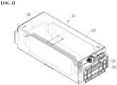
- Fig. 1 is a perspective view showing a battery module according to one embodiment of the present invention.
- the battery module 10 includes a module connector 130 mounted on the outside of a module case 150 accommodating a cell assembly 100 therein.
- Battery cells constituting the cell assembly 100 may be provided as a pouch-type secondary battery, and a plurality of battery cells may be stacked and aligned in the cell assembly 100.
- the plurality of battery cells may be electrically connected to each other, and each of the battery cells may include an electrode assembly, a battery case accommodating the electrode assembly, and an electrode lead protruding out of the battery case and electrically connected to the electrode assembly.
- the battery module 10 may include various electric components, and may include, for example, an internal circuit board (ICB) and a battery management system (BMS). Electric components such as the ICB and BMS board may be electrically connected to the plurality of battery cells.
- ICB internal circuit board
- BMS battery management system
- the module case 150 forms the exterior of the battery module 10 and accommodates the cell assembly 100 therein; and a busbar assembly is coupled to at least one side or both sides of the cell assembly 100 positioned in a direction where the electrode leads of the cell assembly 100 extend, and an insulating frame 160 may be coupled to the outside of the busbar assembly.
- the busbar assembly may include a busbar frame disposed to cover the cell assembly 100, and a busbar fixed to the busbar frame.
- the busbar frame is composed of an insulator and includes a lead slot through which the electrode leads of the cell assembly 100 can pass.
- the busbar may electrically connect the electrode leads of the cell assembly 100.
- the module connector 130 can be coupled to the busbar assembly, particularly the busbar frame.
- a mounting surface may be formed on the busbar frame, and the module connector 130 may be seated on the mounting surface and coupled thereto.
- the module connector 130 and the mounting surface may have sliding grooves formed on one of them and sliding protrusions formed on the other side so as to have a fastening structure in which they are inserted into each other by sliding.
- the battery module 10 may include a flexible printed circuit board (FPC) configured to sense the battery cells inside the module case 150.
- a terminal is coupled to the terminal portion of the flexible printed circuit board, and is exposed to the outside of the module case 150 and coupled to the module connector 130. Accordingly, the module connector 130 may be electrically connected to the cell assembly 100 through the flexible printed circuit board.
- FPC flexible printed circuit board
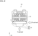
- Fig. 2 is a perspective view showing a connector mounted to a battery module according to one embodiment of the present disclosure
- Fig. 3 is a plan view of the connector shown in Fig. 2 .
- the module connector 130 of the present embodiment includes a body portion 131 connected to a terminal and a fastening portion 135 used for mounting on the outside of the module case 150.
- the terminal is electrically connected to the battery cells through the flexible printed circuit board, and the flexible printed circuit board may be connected to the terminal through a terminal portion. Accordingly, the module connector 130 may transmit electrical and thermal data of each battery cell to a measurement and control machine such as a BMS.
- the fastening portion 135 of the module connector 130 is configured to have elasticity on one side of the body portion 131 facing the mounting surface of the module case 150, thus absorbing shocks or vibrations.
- the fastening portion 135 is configured to impart an elastic force in a first direction (x-axis direction) parallel to the mounting surface or in a second direction (y-axis direction) perpendicular to the mounting surface.
- the module connector 130 is designed to impart an elastic force in the x-axis direction or in the y-axis direction according to the environmental conditions in which the module connector 130 is mounted, or may be also designed to impart an elastic force in both the x-axis direction and the y-axis direction.
- the fastening portion 135 is spaced apart from the body portion 131 to form an empty space E therebetween.
- the fastening portion 135 includes a pair of elastic supports 135a and 135b that are convex outwardly at both sides, wherein the elastic supports 135a and 135b extend in a direction away from the body portion 131 and are coupled to a mounting end 135c at a portion facing the body portion 131.
- the mounting end 135c may have a rail groove and a receiving space so as to be slidably coupled to the mounting surface.
- the pair of elastic supports 135a and 135b are convexly bent outward in opposite directions from each other at both edges and extend from one surface of the body portion 131 to be integral with the mounting end 135c and, thus, form a closed curve.
- This forms an approximately elliptical shape when viewed in a third direction (z-axis direction) perpendicular to the x-axis direction and the y-axis direction, wherein the elliptical shape may have a width in the x-axis direction larger than that in the y-axis direction.
- the width of the pair of elastic supports 135a and 135b spaced apart in the x-axis direction may be formed to be equal to or smaller than the width of the body portion 131.
- the maximum width of the pair of elastic supports 135a and 135b measured in the x-axis direction may be less than or equal to the entire width of the body portion 131 measured in the same direction. Accordingly, even if a load in the x-axis direction or in the y-axis direction is applied to the module connector 130, the elastic supports 135a and 135b of the fastening portion 135 can protrude outside the region set by the edge of the body portion 131 to be prevented from interfering with the surrounding components.
- the fastening portion 135 of the module connector 130 as described above may be manufactured by molding with a resin material.
- the elastic supports 135a and 135b and mounting end (135c) constituting the fastening portion 135 may be integrally formed through molding, and the fastening portion 135 may be integrally formed with the body portion 131.
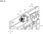
- Fig. 4 is an enlarged partial perspective view showing a state in which a module connector is mounted in a battery module according to one embodiment of the present invention
- Fig. 5 is an enlarged partial front view showing a state in which a module connector is mounted in a battery module according to one embodiment of the present invention.
- the module connector 130 may be aligned such that the body portion 131 faces outward and the fastening portion 135 faces the module case 150 incorporating the cell assembly therein, and be slidably coupled to the mounting surface 142 provided on the busbar assembly.
- Fig. 5 it can be seen that the fastening portion 135 of the module connector 130 forming the empty space E is in contact with and coupled to the module case 150.
- the fastening portion 135 of the module connector 130 can absorb vibrations or shocks which are applied in a direction perpendicular to the main surface of the insulating frame 160 (y-axis direction), or vibrations or shocks which are applied in a direction being parallel to the main surface of the insulating frame 160 and being perpendicular to the ground (or the battery module seating surface) (x-axis direction).
- a structure in which the elastic supports of the fastening portion 135 constituting the module connector 130 is formed in a plurality of pairs may be applied. That is, a plurality of elastic supports are provided on both left and right sides, respectively, and the elastic supports on both sides may be bent in opposite directions so as to be convex outwardly and thus form an elastic structure.
- the elastic supports of the fastening portion 135 constituting the module connector 130 are formed in a pair or a plurality of pairs on both sides, and the elastic supports on both sides may be bent in directions facing each other so as to be convex inwardly and thus form an elastic structure.
- Fig. 6 is a perspective view showing a module connector mounted in a battery module according to the comparative example.
- the module connector 30 shown in Fig. 6 includes a fastening portion 34 extending from one side of the body portion 32 to which a terminal electrically connected to a battery cell is connected.
- the fastening portion 34 is composed of a plurality of pins so that it can be securely fixed to the mounting surface provided on the outside of the module case, wherein the plurality of pins are fixed in a cluster and, thus, are difficult to provide elastic force. Therefore, unlike the fastening portion of the module connector according to the present embodiment, when affected by vibration or shock from the outside, the fastening portion 34 may be damaged or irreversibly deformed because it cannot absorb the vibration or shock.
- one or more of the battery module according to an embodiment of the present invention are packaged in a pack case to form a battery pack.
- the above-mentioned battery module and battery pack comprising the same can be applied to various devices.
- a device may be applied to a vehicle such as an electric bicycle, an electric vehicle, or a hybrid vehicle, but the present invention is not limited thereto, and is applicable to various devices that can use a battery module, which also belongs to the scope of the present disclosure.
Landscapes
- Chemical & Material Sciences (AREA)
- Chemical Kinetics & Catalysis (AREA)
- Electrochemistry (AREA)
- General Chemical & Material Sciences (AREA)
- Engineering & Computer Science (AREA)
- Manufacturing & Machinery (AREA)
- Microelectronics & Electronic Packaging (AREA)
- Battery Mounting, Suspending (AREA)
- Connection Of Batteries Or Terminals (AREA)
Applications Claiming Priority (2)
| Application Number | Priority Date | Filing Date | Title |
|---|---|---|---|
| KR1020190022718A KR102573133B1 (ko) | 2019-02-26 | 2019-02-26 | 충격 흡수 구조를 갖는 커넥터를 포함하는 전지 모듈 |
| PCT/KR2020/002683 WO2020175883A1 (ko) | 2019-02-26 | 2020-02-25 | 충격 흡수 구조를 갖는 커넥터를 포함하는 전지 모듈 |
Publications (3)
| Publication Number | Publication Date |
|---|---|
| EP3780287A1 EP3780287A1 (en) | 2021-02-17 |
| EP3780287A4 EP3780287A4 (en) | 2021-09-15 |
| EP3780287B1 true EP3780287B1 (en) | 2025-06-18 |
Family
ID=72239755
Family Applications (1)
| Application Number | Title | Priority Date | Filing Date |
|---|---|---|---|
| EP20762754.8A Active EP3780287B1 (en) | 2019-02-26 | 2020-02-25 | Battery module including connector having shock absorbing structure |
Country Status (9)
| Country | Link |
|---|---|
| US (1) | US12500304B2 (pl) |
| EP (1) | EP3780287B1 (pl) |
| JP (1) | JP7055487B2 (pl) |
| KR (1) | KR102573133B1 (pl) |
| CN (1) | CN112219319B (pl) |
| ES (1) | ES3035232T3 (pl) |
| HU (1) | HUE071916T2 (pl) |
| PL (1) | PL3780287T3 (pl) |
| WO (1) | WO2020175883A1 (pl) |
Families Citing this family (6)
| Publication number | Priority date | Publication date | Assignee | Title |
|---|---|---|---|---|
| USD978785S1 (en) * | 2020-11-27 | 2023-02-21 | Gs Yuasa International Ltd. | Battery |
| KR102857910B1 (ko) * | 2021-05-11 | 2025-09-09 | 주식회사 엘지에너지솔루션 | 전지 모듈 및 이를 포함하는 전지 팩 |
| KR102618199B1 (ko) * | 2021-12-06 | 2023-12-27 | (주) 에어로매스터 | 가요성 커넥터 장치 및 이를 포함하는 분리형 메모리 모듈 |
| US12160127B2 (en) | 2021-12-09 | 2024-12-03 | Honda Motor Co., Ltd. | Battery terminal fixing apparatus and method for power equipment |
| JP7835900B2 (ja) * | 2022-05-25 | 2026-03-25 | エルジー エナジー ソリューション リミテッド | 電池モジュール |
| US20230397761A1 (en) * | 2022-06-14 | 2023-12-14 | Oesso 5, Llc | Thermostatic cup structure |
Family Cites Families (28)
| Publication number | Priority date | Publication date | Assignee | Title |
|---|---|---|---|---|
| JP3696070B2 (ja) | 2000-09-18 | 2005-09-14 | 三洋電機株式会社 | 弾性接点を備える機器 |
| JP2005019305A (ja) | 2003-06-27 | 2005-01-20 | Advanex Inc | コネクタ |
| CN2772060Y (zh) | 2005-01-28 | 2006-04-12 | 陈碇祈 | 连接器结构 |
| JP5361127B2 (ja) | 2006-12-07 | 2013-12-04 | キヤノン株式会社 | 燃料電池 |
| US8252441B2 (en) | 2007-08-31 | 2012-08-28 | Micro Power Electronics, Inc. | Spacers for fixing battery cells within a battery package casing and associated systems and methods |
| KR101006881B1 (ko) | 2007-12-14 | 2011-01-12 | 주식회사 엘지화학 | 개선된 체결식 구조의 pcm 및 이를 포함하고 있는전지팩 |
| KR101087036B1 (ko) | 2008-12-17 | 2011-11-25 | 주식회사 엘지화학 | 전극단자 연결장치 및 이를 포함하는 전지모듈 어셈블리 |
| JP2010257735A (ja) | 2009-04-24 | 2010-11-11 | Toyota Motor Corp | 組電池 |
| KR101036060B1 (ko) | 2009-05-14 | 2011-05-26 | 삼성에스디아이 주식회사 | 커넥터 및 이를 구비한 배터리 팩 |
| JP2011171987A (ja) | 2010-02-18 | 2011-09-01 | Nec Corp | 接触断の発生を抑えた携帯情報端末のバッテリ接続端子構造 |
| CN101783460A (zh) * | 2010-03-01 | 2010-07-21 | 李立国 | 一种电动汽车动力电池箱盲插式连接器隔振装置 |
| EP2763255B1 (en) * | 2011-09-29 | 2019-07-31 | Yazaki Corporation | Connector comprising a plurality of terminals and a connector housing |
| KR102002344B1 (ko) | 2012-11-07 | 2019-10-01 | 에스케이이노베이션 주식회사 | 이차전지팩용 센서어셈블리와 이를 갖는 이차전지팩 |
| DE102013215436A1 (de) | 2013-08-06 | 2015-03-05 | Bayerische Motoren Werke Aktiengesellschaft | Vorrichtung zur Aufnahme zumindest eines Energiemoduls für ein Kraftfahrzeug |
| CN204144341U (zh) | 2014-09-29 | 2015-02-04 | 比亚迪股份有限公司 | 电极端子、具有其的电池盖板组件、电池和电池组 |
| KR102395752B1 (ko) | 2015-08-04 | 2022-05-09 | 삼성에스디아이 주식회사 | 배터리 팩 |
| KR102047483B1 (ko) * | 2015-10-30 | 2019-12-02 | 주식회사 엘지화학 | 배터리 모듈 및 이를 포함하는 배터리 팩 |
| KR102210887B1 (ko) | 2016-08-01 | 2021-02-02 | 삼성에스디아이 주식회사 | 배터리 모듈 |
| WO2018080181A1 (ko) | 2016-10-26 | 2018-05-03 | 삼성에스디아이 주식회사 | 인쇄 회로 기판용 커넥터 및 인쇄 회로 기판과 커넥터를 포함한 전지 시스템 |
| EP3316386B1 (en) | 2016-10-26 | 2019-08-21 | Samsung SDI Co., Ltd. | Connector part for a printed circuit board and a battery system comprising the printed circuit board and the connector part |
| CN106848675A (zh) | 2016-12-21 | 2017-06-13 | 苏州华旃航天电器有限公司 | 具有插孔接触件的电连接器 |
| JP6810622B2 (ja) | 2017-01-31 | 2021-01-06 | トヨタ自動車株式会社 | 自動車の駆動用バッテリ保護構造 |
| CN111755903B (zh) | 2017-06-23 | 2022-08-30 | 上海电巴新能源科技有限公司 | 电连接装置 |
| JP7160809B2 (ja) * | 2017-07-27 | 2022-10-25 | 三洋電機株式会社 | 電池パック及びその製造方法 |
| JP7288269B2 (ja) | 2017-10-10 | 2023-06-07 | 古河電池株式会社 | バッテリ装着ユニット、電動機器及び電源ユニット |
| WO2019073949A1 (ja) | 2017-10-10 | 2019-04-18 | マクセルホールディングス株式会社 | バッテリ装着ユニット、電動機器及び電源ユニット |
| KR102280995B1 (ko) * | 2017-11-16 | 2021-07-22 | 주식회사 엘지에너지솔루션 | 커넥터가 설치된 하우징을 포함하는 배터리 모듈 |
| CN208781900U (zh) | 2018-08-29 | 2019-04-23 | 宁波金雄塑料有限公司 | 一种车用蓄电池盖板 |
-
2019
- 2019-02-26 KR KR1020190022718A patent/KR102573133B1/ko active Active
-
2020
- 2020-02-25 ES ES20762754T patent/ES3035232T3/es active Active
- 2020-02-25 PL PL20762754.8T patent/PL3780287T3/pl unknown
- 2020-02-25 EP EP20762754.8A patent/EP3780287B1/en active Active
- 2020-02-25 JP JP2020560829A patent/JP7055487B2/ja active Active
- 2020-02-25 WO PCT/KR2020/002683 patent/WO2020175883A1/ko not_active Ceased
- 2020-02-25 HU HUE20762754A patent/HUE071916T2/hu unknown
- 2020-02-25 US US17/265,955 patent/US12500304B2/en active Active
- 2020-02-25 CN CN202080002920.0A patent/CN112219319B/zh active Active
Also Published As
| Publication number | Publication date |
|---|---|
| PL3780287T3 (pl) | 2025-08-18 |
| EP3780287A4 (en) | 2021-09-15 |
| KR102573133B1 (ko) | 2023-08-30 |
| ES3035232T3 (en) | 2025-09-01 |
| US20210296725A1 (en) | 2021-09-23 |
| KR20200104142A (ko) | 2020-09-03 |
| EP3780287A1 (en) | 2021-02-17 |
| HUE071916T2 (hu) | 2025-10-28 |
| CN112219319A (zh) | 2021-01-12 |
| JP2021521604A (ja) | 2021-08-26 |
| WO2020175883A1 (ko) | 2020-09-03 |
| CN112219319B (zh) | 2022-04-15 |
| US12500304B2 (en) | 2025-12-16 |
| JP7055487B2 (ja) | 2022-04-18 |
Similar Documents
| Publication | Publication Date | Title |
|---|---|---|
| EP3780287B1 (en) | Battery module including connector having shock absorbing structure | |
| US11196120B2 (en) | Battery module, and battery pack and vehicle comprising same | |
| EP3761396B1 (en) | Battery module including protective cover for covering flexible printed circuit board | |
| US10497911B2 (en) | Battery module, battery pack including battery module, and automobile including battery pack | |
| KR102455471B1 (ko) | 배터리 셀, 이를 포함하는 배터리 모듈, 배터리 랙 및 전력 저장 장치 | |
| EP3688826B1 (en) | Battery pack including cell restraint | |
| KR20200069720A (ko) | 인서트 사출된 버스바 조립체를 포함하는 전지 모듈 | |
| JP7154382B2 (ja) | バッテリーパック及びそれを含む自動車 | |
| EP4071903A1 (en) | Battery pack and vehicle comprising same | |
| EP3579298A1 (en) | Battery pack and holder | |
| KR20220101475A (ko) | 배터리 팩 및 이를 포함하는 자동차 | |
| EP3764421B1 (en) | Battery module including connector having bidirectional coupling structure | |
| KR102053965B1 (ko) | 배터리 모듈, 배터리 모듈을 포함하는 배터리 팩 및 배터리 팩을 포함하는 자동차 | |
| KR20200120421A (ko) | 전지 모듈 | |
| EP3688825B1 (en) | Battery pack including cell restraint | |
| KR102111767B1 (ko) | 배터리 팩 및 이러한 배터리 팩을 포함하는 자동차 | |
| KR102850081B1 (ko) | 배터리 팩 | |
| KR20210130549A (ko) | 전지 모듈 및 그 제조 방법 |
Legal Events
| Date | Code | Title | Description |
|---|---|---|---|
| STAA | Information on the status of an ep patent application or granted ep patent |
Free format text: STATUS: THE INTERNATIONAL PUBLICATION HAS BEEN MADE |
|
| PUAI | Public reference made under article 153(3) epc to a published international application that has entered the european phase |
Free format text: ORIGINAL CODE: 0009012 |
|
| STAA | Information on the status of an ep patent application or granted ep patent |
Free format text: STATUS: REQUEST FOR EXAMINATION WAS MADE |
|
| 17P | Request for examination filed |
Effective date: 20201029 |
|
| AK | Designated contracting states |
Kind code of ref document: A1 Designated state(s): AL AT BE BG CH CY CZ DE DK EE ES FI FR GB GR HR HU IE IS IT LI LT LU LV MC MK MT NL NO PL PT RO RS SE SI SK SM TR |
|
| AX | Request for extension of the european patent |
Extension state: BA ME |
|
| A4 | Supplementary search report drawn up and despatched |
Effective date: 20210812 |
|
| RIC1 | Information provided on ipc code assigned before grant |
Ipc: H01M 50/524 20210101ALI20210806BHEP Ipc: H01M 50/503 20210101ALI20210806BHEP Ipc: H01R 13/24 20060101ALI20210806BHEP Ipc: H01R 13/533 20060101AFI20210806BHEP |
|
| RAP1 | Party data changed (applicant data changed or rights of an application transferred) |
Owner name: LG ENERGY SOLUTION LTD. |
|
| RAP3 | Party data changed (applicant data changed or rights of an application transferred) |
Owner name: LG ENERGY SOLUTION, LTD. |
|
| DAV | Request for validation of the european patent (deleted) | ||
| DAX | Request for extension of the european patent (deleted) | ||
| STAA | Information on the status of an ep patent application or granted ep patent |
Free format text: STATUS: EXAMINATION IS IN PROGRESS |
|
| 17Q | First examination report despatched |
Effective date: 20230209 |
|
| GRAP | Despatch of communication of intention to grant a patent |
Free format text: ORIGINAL CODE: EPIDOSNIGR1 |
|
| STAA | Information on the status of an ep patent application or granted ep patent |
Free format text: STATUS: GRANT OF PATENT IS INTENDED |
|
| INTG | Intention to grant announced |
Effective date: 20250210 |
|
| GRAS | Grant fee paid |
Free format text: ORIGINAL CODE: EPIDOSNIGR3 |
|
| GRAA | (expected) grant |
Free format text: ORIGINAL CODE: 0009210 |
|
| STAA | Information on the status of an ep patent application or granted ep patent |
Free format text: STATUS: THE PATENT HAS BEEN GRANTED |
|
| P01 | Opt-out of the competence of the unified patent court (upc) registered |
Free format text: CASE NUMBER: APP_17975/2025 Effective date: 20250414 |
|
| AK | Designated contracting states |
Kind code of ref document: B1 Designated state(s): AL AT BE BG CH CY CZ DE DK EE ES FI FR GB GR HR HU IE IS IT LI LT LU LV MC MK MT NL NO PL PT RO RS SE SI SK SM TR |
|
| REG | Reference to a national code |
Ref country code: GB Ref legal event code: FG4D |
|
| REG | Reference to a national code |
Ref country code: CH Ref legal event code: EP |
|
| REG | Reference to a national code |
Ref country code: DE Ref legal event code: R096 Ref document number: 602020052958 Country of ref document: DE |
|
| REG | Reference to a national code |
Ref country code: CH Ref legal event code: EP |
|
| REG | Reference to a national code |
Ref country code: IE Ref legal event code: FG4D |
|
| REG | Reference to a national code |
Ref country code: SE Ref legal event code: TRGR |
|
| REG | Reference to a national code |
Ref country code: ES Ref legal event code: FG2A Ref document number: 3035232 Country of ref document: ES Kind code of ref document: T3 Effective date: 20250901 |
|
| PG25 | Lapsed in a contracting state [announced via postgrant information from national office to epo] |
Ref country code: FI Free format text: LAPSE BECAUSE OF FAILURE TO SUBMIT A TRANSLATION OF THE DESCRIPTION OR TO PAY THE FEE WITHIN THE PRESCRIBED TIME-LIMIT Effective date: 20250618 |
|
| REG | Reference to a national code |
Ref country code: LT Ref legal event code: MG9D |
|
| PG25 | Lapsed in a contracting state [announced via postgrant information from national office to epo] |
Ref country code: NO Free format text: LAPSE BECAUSE OF FAILURE TO SUBMIT A TRANSLATION OF THE DESCRIPTION OR TO PAY THE FEE WITHIN THE PRESCRIBED TIME-LIMIT Effective date: 20250918 Ref country code: GR Free format text: LAPSE BECAUSE OF FAILURE TO SUBMIT A TRANSLATION OF THE DESCRIPTION OR TO PAY THE FEE WITHIN THE PRESCRIBED TIME-LIMIT Effective date: 20250919 |
|
| PG25 | Lapsed in a contracting state [announced via postgrant information from national office to epo] |
Ref country code: BG Free format text: LAPSE BECAUSE OF FAILURE TO SUBMIT A TRANSLATION OF THE DESCRIPTION OR TO PAY THE FEE WITHIN THE PRESCRIBED TIME-LIMIT Effective date: 20250618 |
|
| PG25 | Lapsed in a contracting state [announced via postgrant information from national office to epo] |
Ref country code: HR Free format text: LAPSE BECAUSE OF FAILURE TO SUBMIT A TRANSLATION OF THE DESCRIPTION OR TO PAY THE FEE WITHIN THE PRESCRIBED TIME-LIMIT Effective date: 20250618 |
|
| PG25 | Lapsed in a contracting state [announced via postgrant information from national office to epo] |
Ref country code: RS Free format text: LAPSE BECAUSE OF FAILURE TO SUBMIT A TRANSLATION OF THE DESCRIPTION OR TO PAY THE FEE WITHIN THE PRESCRIBED TIME-LIMIT Effective date: 20250918 |
|
| REG | Reference to a national code |
Ref country code: NL Ref legal event code: MP Effective date: 20250618 |
|
| REG | Reference to a national code |
Ref country code: HU Ref legal event code: AG4A Ref document number: E071916 Country of ref document: HU |
|
| PG25 | Lapsed in a contracting state [announced via postgrant information from national office to epo] |
Ref country code: LV Free format text: LAPSE BECAUSE OF FAILURE TO SUBMIT A TRANSLATION OF THE DESCRIPTION OR TO PAY THE FEE WITHIN THE PRESCRIBED TIME-LIMIT Effective date: 20250618 |
|
| PG25 | Lapsed in a contracting state [announced via postgrant information from national office to epo] |
Ref country code: NL Free format text: LAPSE BECAUSE OF FAILURE TO SUBMIT A TRANSLATION OF THE DESCRIPTION OR TO PAY THE FEE WITHIN THE PRESCRIBED TIME-LIMIT Effective date: 20250618 |
|
| PG25 | Lapsed in a contracting state [announced via postgrant information from national office to epo] |
Ref country code: PT Free format text: LAPSE BECAUSE OF FAILURE TO SUBMIT A TRANSLATION OF THE DESCRIPTION OR TO PAY THE FEE WITHIN THE PRESCRIBED TIME-LIMIT Effective date: 20251020 |
|
| REG | Reference to a national code |
Ref country code: AT Ref legal event code: MK05 Ref document number: 1805112 Country of ref document: AT Kind code of ref document: T Effective date: 20250618 |
|
| PG25 | Lapsed in a contracting state [announced via postgrant information from national office to epo] |
Ref country code: IS Free format text: LAPSE BECAUSE OF FAILURE TO SUBMIT A TRANSLATION OF THE DESCRIPTION OR TO PAY THE FEE WITHIN THE PRESCRIBED TIME-LIMIT Effective date: 20251018 |
|
| PG25 | Lapsed in a contracting state [announced via postgrant information from national office to epo] |
Ref country code: AT Free format text: LAPSE BECAUSE OF FAILURE TO SUBMIT A TRANSLATION OF THE DESCRIPTION OR TO PAY THE FEE WITHIN THE PRESCRIBED TIME-LIMIT Effective date: 20250618 Ref country code: SM Free format text: LAPSE BECAUSE OF FAILURE TO SUBMIT A TRANSLATION OF THE DESCRIPTION OR TO PAY THE FEE WITHIN THE PRESCRIBED TIME-LIMIT Effective date: 20250618 |
|
| PG25 | Lapsed in a contracting state [announced via postgrant information from national office to epo] |
Ref country code: CZ Free format text: LAPSE BECAUSE OF FAILURE TO SUBMIT A TRANSLATION OF THE DESCRIPTION OR TO PAY THE FEE WITHIN THE PRESCRIBED TIME-LIMIT Effective date: 20250618 |
|
| PG25 | Lapsed in a contracting state [announced via postgrant information from national office to epo] |
Ref country code: EE Free format text: LAPSE BECAUSE OF FAILURE TO SUBMIT A TRANSLATION OF THE DESCRIPTION OR TO PAY THE FEE WITHIN THE PRESCRIBED TIME-LIMIT Effective date: 20250618 |
|
| PG25 | Lapsed in a contracting state [announced via postgrant information from national office to epo] |
Ref country code: SK Free format text: LAPSE BECAUSE OF FAILURE TO SUBMIT A TRANSLATION OF THE DESCRIPTION OR TO PAY THE FEE WITHIN THE PRESCRIBED TIME-LIMIT Effective date: 20250618 Ref country code: RO Free format text: LAPSE BECAUSE OF FAILURE TO SUBMIT A TRANSLATION OF THE DESCRIPTION OR TO PAY THE FEE WITHIN THE PRESCRIBED TIME-LIMIT Effective date: 20250618 |
|
| PGFP | Annual fee paid to national office [announced via postgrant information from national office to epo] |
Ref country code: HU Payment date: 20260227 Year of fee payment: 7 |
|
| PGFP | Annual fee paid to national office [announced via postgrant information from national office to epo] |
Ref country code: SE Payment date: 20260121 Year of fee payment: 7 |
|
| PGFP | Annual fee paid to national office [announced via postgrant information from national office to epo] |
Ref country code: GB Payment date: 20260122 Year of fee payment: 7 |
|
| PGFP | Annual fee paid to national office [announced via postgrant information from national office to epo] |
Ref country code: ES Payment date: 20260324 Year of fee payment: 7 |
|
| PG25 | Lapsed in a contracting state [announced via postgrant information from national office to epo] |
Ref country code: DK Free format text: LAPSE BECAUSE OF FAILURE TO SUBMIT A TRANSLATION OF THE DESCRIPTION OR TO PAY THE FEE WITHIN THE PRESCRIBED TIME-LIMIT Effective date: 20250618 |
|
| PGFP | Annual fee paid to national office [announced via postgrant information from national office to epo] |
Ref country code: DE Payment date: 20260120 Year of fee payment: 7 |
|
| PG25 | Lapsed in a contracting state [announced via postgrant information from national office to epo] |
Ref country code: IT Free format text: LAPSE BECAUSE OF FAILURE TO SUBMIT A TRANSLATION OF THE DESCRIPTION OR TO PAY THE FEE WITHIN THE PRESCRIBED TIME-LIMIT Effective date: 20250618 |
|
| PGFP | Annual fee paid to national office [announced via postgrant information from national office to epo] |
Ref country code: BE Payment date: 20260121 Year of fee payment: 7 |
|
| PGFP | Annual fee paid to national office [announced via postgrant information from national office to epo] |
Ref country code: FR Payment date: 20260121 Year of fee payment: 7 |
|
| PLBE | No opposition filed within time limit |
Free format text: ORIGINAL CODE: 0009261 |
|
| STAA | Information on the status of an ep patent application or granted ep patent |
Free format text: STATUS: NO OPPOSITION FILED WITHIN TIME LIMIT |