EP3780288A1 - Dispositif de fermeture à contact électrique - Google Patents
Dispositif de fermeture à contact électrique Download PDFInfo
- Publication number
- EP3780288A1 EP3780288A1 EP20195515.0A EP20195515A EP3780288A1 EP 3780288 A1 EP3780288 A1 EP 3780288A1 EP 20195515 A EP20195515 A EP 20195515A EP 3780288 A1 EP3780288 A1 EP 3780288A1
- Authority
- EP
- European Patent Office
- Prior art keywords
- engagement
- closure
- closure part
- another
- parts
- Prior art date
- Legal status (The legal status is an assumption and is not a legal conclusion. Google has not performed a legal analysis and makes no representation as to the accuracy of the status listed.)
- Granted
Links
Images


Classifications
-
- B—PERFORMING OPERATIONS; TRANSPORTING
- B62—LAND VEHICLES FOR TRAVELLING OTHERWISE THAN ON RAILS
- B62J—CYCLE SADDLES OR SEATS; AUXILIARY DEVICES OR ACCESSORIES SPECIALLY ADAPTED TO CYCLES AND NOT OTHERWISE PROVIDED FOR, e.g. ARTICLE CARRIERS OR CYCLE PROTECTORS
- B62J6/00—Arrangement of optical signalling or lighting devices on cycles; Mounting or supporting thereof; Circuits therefor
- B62J6/02—Headlights
-
- B—PERFORMING OPERATIONS; TRANSPORTING
- B62—LAND VEHICLES FOR TRAVELLING OTHERWISE THAN ON RAILS
- B62J—CYCLE SADDLES OR SEATS; AUXILIARY DEVICES OR ACCESSORIES SPECIALLY ADAPTED TO CYCLES AND NOT OTHERWISE PROVIDED FOR, e.g. ARTICLE CARRIERS OR CYCLE PROTECTORS
- B62J6/00—Arrangement of optical signalling or lighting devices on cycles; Mounting or supporting thereof; Circuits therefor
- B62J6/04—Rear lights
-
- F—MECHANICAL ENGINEERING; LIGHTING; HEATING; WEAPONS; BLASTING
- F16—ENGINEERING ELEMENTS AND UNITS; GENERAL MEASURES FOR PRODUCING AND MAINTAINING EFFECTIVE FUNCTIONING OF MACHINES OR INSTALLATIONS; THERMAL INSULATION IN GENERAL
- F16B—DEVICES FOR FASTENING OR SECURING CONSTRUCTIONAL ELEMENTS OR MACHINE PARTS TOGETHER, e.g. NAILS, BOLTS, CIRCLIPS, CLAMPS, CLIPS OR WEDGES; JOINTS OR JOINTING
- F16B1/00—Devices for securing together, or preventing relative movement between, constructional elements or machine parts
-
- H—ELECTRICITY
- H01—ELECTRIC ELEMENTS
- H01R—ELECTRICALLY-CONDUCTIVE CONNECTIONS; STRUCTURAL ASSOCIATIONS OF A PLURALITY OF MUTUALLY-INSULATED ELECTRICAL CONNECTING ELEMENTS; COUPLING DEVICES; CURRENT COLLECTORS
- H01R13/00—Details of coupling devices of the kinds covered by groups H01R12/70 or H01R24/00 - H01R33/00
- H01R13/62—Means for facilitating engagement or disengagement of coupling parts or for holding them in engagement
- H01R13/6205—Two-part coupling devices held in engagement by a magnet
-
- H—ELECTRICITY
- H01—ELECTRIC ELEMENTS
- H01R—ELECTRICALLY-CONDUCTIVE CONNECTIONS; STRUCTURAL ASSOCIATIONS OF A PLURALITY OF MUTUALLY-INSULATED ELECTRICAL CONNECTING ELEMENTS; COUPLING DEVICES; CURRENT COLLECTORS
- H01R13/00—Details of coupling devices of the kinds covered by groups H01R12/70 or H01R24/00 - H01R33/00
- H01R13/62—Means for facilitating engagement or disengagement of coupling parts or for holding them in engagement
- H01R13/627—Snap or like fastening
- H01R13/6271—Latching means integral with the housing
-
- B—PERFORMING OPERATIONS; TRANSPORTING
- B62—LAND VEHICLES FOR TRAVELLING OTHERWISE THAN ON RAILS
- B62J—CYCLE SADDLES OR SEATS; AUXILIARY DEVICES OR ACCESSORIES SPECIALLY ADAPTED TO CYCLES AND NOT OTHERWISE PROVIDED FOR, e.g. ARTICLE CARRIERS OR CYCLE PROTECTORS
- B62J6/00—Arrangement of optical signalling or lighting devices on cycles; Mounting or supporting thereof; Circuits therefor
- B62J6/02—Headlights
- B62J6/028—Headlights specially adapted for rider-propelled cycles with or without additional source of power
- B62J6/03—Supporting means therefor, e.g. mounting brackets
-
- F—MECHANICAL ENGINEERING; LIGHTING; HEATING; WEAPONS; BLASTING
- F16—ENGINEERING ELEMENTS AND UNITS; GENERAL MEASURES FOR PRODUCING AND MAINTAINING EFFECTIVE FUNCTIONING OF MACHINES OR INSTALLATIONS; THERMAL INSULATION IN GENERAL
- F16B—DEVICES FOR FASTENING OR SECURING CONSTRUCTIONAL ELEMENTS OR MACHINE PARTS TOGETHER, e.g. NAILS, BOLTS, CIRCLIPS, CLAMPS, CLIPS OR WEDGES; JOINTS OR JOINTING
- F16B2200/00—Constructional details of connections not covered for in other groups of this subclass
- F16B2200/83—Use of a magnetic material
-
- F—MECHANICAL ENGINEERING; LIGHTING; HEATING; WEAPONS; BLASTING
- F16—ENGINEERING ELEMENTS AND UNITS; GENERAL MEASURES FOR PRODUCING AND MAINTAINING EFFECTIVE FUNCTIONING OF MACHINES OR INSTALLATIONS; THERMAL INSULATION IN GENERAL
- F16B—DEVICES FOR FASTENING OR SECURING CONSTRUCTIONAL ELEMENTS OR MACHINE PARTS TOGETHER, e.g. NAILS, BOLTS, CIRCLIPS, CLAMPS, CLIPS OR WEDGES; JOINTS OR JOINTING
- F16B2200/00—Constructional details of connections not covered for in other groups of this subclass
- F16B2200/93—Fastener comprising feature for establishing a good electrical connection, e.g. electrostatic discharge or insulation feature
-
- H—ELECTRICITY
- H01—ELECTRIC ELEMENTS
- H01R—ELECTRICALLY-CONDUCTIVE CONNECTIONS; STRUCTURAL ASSOCIATIONS OF A PLURALITY OF MUTUALLY-INSULATED ELECTRICAL CONNECTING ELEMENTS; COUPLING DEVICES; CURRENT COLLECTORS
- H01R13/00—Details of coupling devices of the kinds covered by groups H01R12/70 or H01R24/00 - H01R33/00
- H01R13/62—Means for facilitating engagement or disengagement of coupling parts or for holding them in engagement
- H01R13/627—Snap or like fastening
- H01R13/6275—Latching arms not integral with the housing
Definitions
- the invention relates to a closure device for connecting two parts according to the preamble of claim 1.
- Such a closure device comprises a first closure part which has a first engagement projection and a second closure part which has a second engagement projection.
- first closure part and the second closure part can be attached to one another and are mechanically connected to one another in a closed position by the first engagement projection and the second engagement projection being positively engaged with one another in the closed position.
- a magnetic device acting between the first closure part and the second closure part serves to support the attachment of the first closure part and the second closure part to one another by providing a magnetic force of attraction.
- a closure part is fastened to an object via a fastening plate.
- the fastening plate here has openings which can be brought into engagement with engagement projections of the closure part.
- Spring tongues are provided on the openings, which deflect elastically when the closure part is attached to the fastening plate and, after establishing a positive connection between the engagement projections of the closure part and the edge of the openings in the fastening plate, return to their basic position in order to release the engagement projections from their basic position Lock intervention.
- a pin is arranged on a first closure part, which can be brought into engagement with an engagement recess on a second closure part.
- a locking element which, after the engagement of the pin of the first closure part with the engagement recess of the second closure part, returns to a basic position in which the engagement of the pin with the engagement recess is locked.
- the locking element can be actuated to release the pin and remove it from the engagement recess.
- closure devices that can be closed in a haptically pleasant, smooth-running manner, ensure a firm hold in the closed position and thus a secure connection between the parts to be connected and, moreover, can be opened in an easy, convenient manner.
- electrical assemblies may be desirable to connect electrical assemblies to one another in order to transmit electrical signals between the electrical assemblies, for example in order to provide a power supply or to transmit data signals.
- the US 2009 / 0215283A1 describes a connector having a male and female connector.
- the plug has a plurality of contacts and a first magnet.
- the socket forms a plurality of insertion holes and has a second magnet. Magnetic repulsion should be made available via the magnets when the plug and socket are connected to one another.
- the object of the present invention is to provide a locking device which enables easy closing, a firm hold in the closed position and simple opening and which can be particularly suitable for connecting electrical assemblies.
- the first closure part has a first electrical contact element
- the second closure part has a second electrical contact element.
- the first electrical contact element and the second electrical contact element are in operative connection with one another in an electrically contacting manner.
- Electrical contact can thus be established via the closure device with two assemblies mechanically held together.
- the locking device thus allows assemblies to be attached to one another in a simple manner, with a simple, magnetically assisted closing process and with a mechanically firm hold in the closed position.
- electrical contacting of the contact elements is simultaneously effected, so that in the closed position the closure parts of the closure device are also electrically connected to one another.
- the present closure device provides (at least) one engagement projection on two closure parts, which is designed in the manner of an undercut and can, for example, be rigidly arranged on a base body of the respectively assigned closure part.
- the engagement projections are brought into engagement with one another to close the closure device, for this purpose the engagement projections are moved past one another, for example, until the first engagement projection can be pushed into engagement with the second engagement projection in a form-fitting manner.
- the engagement projections establish a firm hold of the closure parts on one another, so that the closure device can be loaded without the closure parts becoming detached from one another.
- a locking element is additionally provided in one embodiment, which is designed, for example, as an elastic spring tongue arranged on a base body of one of the locking parts or as a resilient, for example pivotable locking part arranged on the base body.
- the locking element During or after the engagement is established, the locking element returns to its basic position and, in this basic position, blocks the positive engagement of the first engagement projection with the second engagement projection opposite to the engagement direction. The retention of the first engagement projection on the second engagement projection and thus of the first closure part on the second closure part is thus secured, so that the closure device cannot be opened inadvertently.
- magnetic means are provided, for example in the form of a magnet on the first closure part and a magnet on the second closure part or in the form of a magnet on one of the closure parts and a magnetic armature in the form of a component made of a ferromagnetic material on the other of the closure parts are trained.
- the magnetic means act between the first closure part and the second closure part in that they interact magnetically attractively when the first closure part is attached to the second closure part and thus the first closure part is drawn into engagement with the second closure part with magnetic support.
- the magnetic means can advantageously be dimensioned in such a way that the engagement of the first engagement projection with the second engagement projection when the closure parts are attached to one another is produced largely automatically and, in particular, the escape of the locking element when the closure parts are attached to one another is largely automatic in a magnetically supported manner.
- an easy-to-close closure is provided in which the closure parts only have to be attached to one another in a comparatively imprecise manner for closing and the actual closure of the closure then takes place largely automatically in a magnetically supported manner.
- the locking element can be designed such that it returns to its basic position when the engagement is established or only after the engagement has been established between the first engagement projection and the second engagement projection.
- the locking element can, for example, snap back into its basic position as soon as the engagement is established (i.e. after the engagement has been established). It is also possible, however, that the locking element, due to its elastic design, already causes a bias on the other closure part when the engagement is established, which presses the first engagement projection in the engagement direction into engagement with the second engagement projection and thus already supports the engagement when establishing the engagement.
- the locking element can, for example, be pivotably arranged on the associated closure part.
- the locking element can be spring-loaded in the direction of its basic position, so that after deflection when being applied, the locking element automatically returns to its basic position when the locking parts are in the closed position or are approaching their closed position.
- the first engagement projection of the first closure part is in positive engagement with the second engagement projection of the second closure part.
- This engagement is blocked by the locking element in that the locking element prevents the locking parts from moving towards one another against the direction of engagement, so that the engagement projections cannot be disengaged from one another against the direction of engagement.
- the blocking can be canceled, for example by the blocking element being deflected again from its basic position, for example by manual operation. If the locking of the positive engagement between the engagement projections of the first closure part and the second closure part is canceled, the engagement projections can counter to the Engagement direction are disengaged from each other, so that the closure parts can be released from each other.
- the first closure part and / or the second closure part have a run-up bevel which is designed in such a way that when the first closure part is attached to the second closure part in a closing direction different from the engagement direction, the first engagement projection runs onto the second engagement projection and the first closure part runs against it is urged in the engaging direction until the first engaging projection is engageable with the second engaging projection in the engaging direction.
- the closing direction is directed, for example, transversely to the direction of engagement.
- the run-up slope describes an inclined plane at an angle between z. B. 30 ° to 60 °, in particular 45 ° (based on the surface normal of the inclined plane) is directed to the closing direction and the direction of engagement. Such a run-up slope facilitates the attachment of the closure parts to one another.
- the engagement projections are designed as rigid elements on a base body of the closure parts
- the engagement projections have to be moved past one another for engagement, whereby it is also necessary to move the first engagement projection (which is designed in the manner of an undercut) against the engagement direction so far relative to move to the second engagement projection so that the engagement projections formed in the manner of undercuts can be brought into engagement with one another.
- This movement counter to the direction of engagement is supported by the run-up slope, along which the closure parts slide along one another until the engagement projections can be brought into engagement with one another.
- the magnetic device is advantageously formed by at least one first magnetic element of the first closure part and at least one second magnetic element of the second closure part.
- the magnetic elements are advantageously arranged on the closure parts in such a way that they attract each other magnetically when the first closure part is attached to the second closure part, but in the closed position - viewed along the direction of engagement - the first magnetic element and the second magnetic element are offset from one another in such a way that a magnetic attraction force acts on the first locking part in the engaging direction.
- the magnetic device thus causes a preload between the closure parts, which tries to pull the first engagement projection in the engagement direction into engagement with the second engagement projection, and thus magnetically supports the engagement and also the retention of the first engagement projection in the second engagement projection.
- the magnetic element of the first closure part is thus in front of the magnetic element of the second Closing part arranged so that the magnetic force of attraction between the magnets has at least one force component in the direction of engagement.
- the magnetic device has a magnetically attractive effect in the closing direction, which can be directed approximately perpendicular to the direction of engagement, for example. Due to the effect of the magnetic device, the closure parts are mutually attracted when they are applied in the closing direction, the force effect between the magnetic means being such that the first engagement projection of the first closure part is brought into engagement with the second engagement projection of the second closure part in a magnetically assisted manner and thus the closing of the closure device can be done largely automatically in a magnetically assisted manner.
- a pair of two magnetic elements can be provided on each closure part, which are offset from one another along the direction of engagement. In this way, tilting of the closure parts with respect to one another when closing the closure device can be counteracted. In addition, an advantageous force effect in the direction of engagement of the engagement projections with one another can be achieved.
- the magnet elements can be designed as permanent magnet elements, the magnet elements of the closure parts in this case facing each other with different magnetic poles and thus interacting in a magnetically attractive manner.
- the magnetic elements can be formed on the one hand by permanent magnet elements and on the other hand, for example, by ferromagnetic elements (magnetic armatures) that face one another and interact so that there is a magnetic force of attraction between the closure parts.
- the first engagement projection on the first closure part and the second engagement projection on the second closure part are advantageously shaped and designed in such a way that the engagement is strengthened when the closure device is loaded.
- two engagement projections can be provided on each of the first closure part and the second closure part which extend at an (acute) angle to one another, so that a V-shape results.
- the tip of the V points in the engagement direction, which preferably also corresponds to a loading direction, so that in the loaded state the hold of the engagement projections of the first closure part in the engagement projections of the second closure part is reinforced.
- the V shape is also advantageous with regard to two other aspects. Firstly, by virtue of the V-shaped arrangement, forces which deviate from the loading direction within an angle predetermined by the V-shape are advantageously absorbed by the form fit between the first engagement projections and the second engagement projections. Secondly, the V-shape stabilizes such that pivoting forces that act on the closure in the closed position about the closing direction can be absorbed over a comparatively large effective width (compared to the depth of the engagement projections). The effective width here is approximately the width of the V-shaped engagement projections in the loading direction.
- first engagement projection and the second engagement projection can each have an arcuate shape.
- the two first engagement projections of the first closure part and / or the two second engagement projections of the second closure part can be connected to one another and thus create a continuous, but possibly angled engagement device.
- the engagement projections can also be separated from one another so that there is a gap between the two first engagement projections and / or the two second engagement projections.
- each closure part which are offset from one another along the engagement direction.
- the engagement projections can be arranged in the manner of a row or in the manner of a matrix on the respective closure part, so that several engagement projections are brought into engagement with one another for closing.
- the number of locking elements does not have to correspond to the number of engagement projections. In principle, a single locking element is sufficient for locking the movement of the first closure part against the direction of engagement relative to the second closure part. However, several locking elements can advantageously also be present.
- Engagement projections can, for example, also be arranged periodically or in groups on the closure parts, so that the closure parts can be brought into engagement with one another in different closed positions.
- the engagement projections can also be implemented by groups of V-shaped or arcuate engagement projections arranged in the manner of a row or matrix.
- the first closure part has an engagement projection in addition to the first engagement device
- the second closure part likewise has an engagement projection in addition to the second engagement device.
- the engagement projection additional to the first engagement means is offset from the first engagement projections along the engagement direction
- the engagement projection additional to the second engagement means is offset from the second engagement projections along the engagement direction.
- the engagement projection additional to the first engagement device and the engagement projection additional to the second engagement device extend transversely (and in a straight line) to the engagement direction.
- the additional engagement projection on each closure part thus extends transversely to the direction of engagement.
- the closure device when used as intended, the closure device is arranged such that the engagement direction extends vertically, the additional engagement projections are advantageously arranged above the first engagement device and the second engagement device, which can bring about an advantageous hold of the closure device.
- At least one of the electrical contact elements has a contact spring which is elastically deformed when the closure parts are attached to one another. Due to the contact spring, the contact elements of the closure parts come into contact with one another under elastic pretension when the closure parts are placed against one another, so that favorable electrical contacting can be provided. In the closed position, the contact spring of one contact element presses against the other contact element, so that reliable electrical contact is ensured.
- the contact elements of the closure parts advantageously rub against one another when the closure device is closed.
- the contact elements can each be arranged on a base body of the associated closure part and can point to one another with contact surfaces in such a way that the contact elements drag tangentially against one another when the engagement projections of the closure parts are brought into engagement in the engagement direction.
- the contact elements slide against one another when the closure device is opened, that is, when the closure parts are released from one another against the engagement direction.
- one of the closure parts has a guide element, for example in the form of a projection protruding from a base body, which engages with a guide opening of the other closure part when the closure parts are attached. Via the guide element and its engagement in the associated guide opening of the other closure part, a guide of the closure parts to one another is thus provided, in particular along the engagement direction in which the engagement projections of the closure parts are to be brought into engagement when the closure parts are attached.
- each closure part can have a base body which is composed of two sub-bodies.
- the partial bodies can be made of different materials, for example different plastic materials (for example with a different hardness) or on the one hand from a metal material and on the other hand from a plastic material.
- an inner partial body can be made of an electrically insulating material for electrically insulating the contact element arranged on the respective closure part, while an outer partial body can be made, for example, of a metal material to provide a resilient, impact-resistant housing.
- first engagement projection on the first closure part and the second engagement projection on the second closure part can be shaped and designed in such a way that the engagement is strengthened when the closure device is loaded.
- two engagement projections can be provided on each of the first closure part and the second closure part which extend at an (acute) angle to one another, so that a V-shape results.
- the tip of the V points in the engagement direction, which preferably also corresponds to a loading direction, so that in the loaded state the hold of the engagement projections of the first closure part in the engagement projections of the second closure part is reinforced.
- the first closure part has a first electrical contact element
- the second closure part has a second electrical contact element.
- the first electrical contact element and the second electrical contact element are in operative connection with one another in an electrically contacting manner. Electrical contact can thus be established via the closure device with two assemblies mechanically held together.
- the locking device thus allows assemblies to be attached to one another in a simple manner, with a simple, magnetically assisted closing process and with a mechanically firm hold in the closed position.
- electrical contacting of the contact elements is simultaneously effected, so that in the closed position the closure parts of the closure device are also electrically connected to one another.
- a locking element is additionally provided in one embodiment, which is designed, for example, as an elastic spring tongue arranged on a base body of one of the closure parts or as a resilient, for example pivotable, locking part on the base body is.
- the locking element gives way when attaching the first closure part to the second closure part in such a way that the first engagement projection of the first closure part can be pushed in the engagement direction into engagement with the second engagement projection of the second closure part. When it is applied, the locking element is thus pushed aside in such a way that the first engagement projection can be guided into engagement with the second engagement projection.
- the locking element During or after the engagement is established, the locking element returns to its basic position and, in this basic position, blocks the positive engagement of the first engagement projection with the second engagement projection opposite to the engagement direction. The retention of the first engagement projection on the second engagement projection and thus the first closure part on the second closure part is thus secured, so that the closure device cannot be opened inadvertently.
- the locking element can be designed such that it returns to its basic position when the engagement is established or only after the engagement has been established between the first engagement projection and the second engagement projection.
- the locking element can, for example, snap back into its basic position as soon as the engagement is established (i.e. after the engagement has been established). It is also possible, however, that the locking element, due to its elastic design, already causes a bias on the other closure part when the engagement is established, which presses the first engagement projection in the engagement direction into engagement with the second engagement projection and thus already supports the engagement when establishing the engagement.
- the locking element can, for example, be pivotably arranged on the associated closure part.
- the locking element can be spring-loaded in the direction of its basic position, so that after deflection when being applied, the locking element automatically returns to its basic position when the locking parts are in the closed position or are approaching their closed position.
- the first engagement projection of the first closure part is in positive engagement with the second engagement projection of the second closure part.
- This engagement is blocked by the locking element in that the locking element prevents the locking parts from moving towards one another against the direction of engagement, so that the engagement projections cannot be disengaged from one another against the direction of engagement.
- the blocking can be canceled, for example by the blocking element being deflected again from its basic position, for example by manual operation. Is the blocking of the positive engagement between the engagement projections of the first closure part and the second closure part is canceled, the engagement projections can be disengaged from one another counter to the direction of engagement, so that the closure parts can be released from one another.
- the magnetic device has a magnetically attractive effect in the closing direction, which can be directed approximately perpendicular to the direction of engagement, for example. Due to the effect of the magnetic device, the closure parts are mutually attracted when they are applied in the closing direction, the force effect between the magnetic means being such that the first engagement projection of the first closure part is brought into engagement with the second engagement projection of the second closure part in a magnetically assisted manner and thus the closing of the closure device can be done largely automatically in a magnetically assisted manner.
- a pair of two magnetic elements can be provided on each closure part, which are offset from one another along the direction of engagement. In this way, tilting of the closure parts with respect to one another when closing the closure device can be counteracted. In addition, an advantageous force effect in the direction of engagement of the engagement projections with one another can be achieved.
- the magnet elements can be designed as permanent magnet elements, the magnet elements of the closure parts in this case facing each other with different magnetic poles and thus interacting in a magnetically attractive manner.
- the magnetic elements can be formed on the one hand by permanent magnet elements and on the other hand, for example, by ferromagnetic elements (magnetic armatures) that face one another and interact so that there is a magnetic force of attraction between the closure parts.
- one of the closure parts has a guide element, for example in the form of a projection protruding from a base body, which engages with a guide opening of the other closure part when the closure parts are attached. Via the guide element and its engagement in the associated guide opening of the other closure part, a guide of the closure parts to one another is thus provided, in particular along the engagement direction in which the engagement projections of the closure parts are to be brought into engagement when the closure parts are attached.
- each closure part can have a base body which is composed of two sub-bodies.
- the body parts can be made here be made of different materials, for example from different plastic materials (for example with a different hardness) or on the one hand from a metal material and on the other hand from a plastic material.
- an inner partial body can be made of an electrically insulating material for electrically insulating the contact element arranged on the respective closure part, while an outer partial body can be made, for example, of a metal material to provide a resilient, impact-resistant housing.
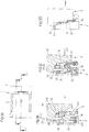
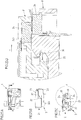
- Figures 1 through 17A-17D such as Figure 31A , 31B to 34A , 34B show an embodiment of a closure device 1, which has two closure parts 2, 3 and serves to releasably connect two parts to one another.
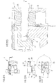
- each closure part 2, 3 has a base body 20, 30 which is composed of two sub-bodies 200, 201, 300, 301, which can be made of different materials.
- the partial bodies 200, 201, 300, 301 can be made from different plastic materials or, on the one hand, from a plastic material and, on the other hand, from a metal material.
- An engagement device 22, 32 is arranged on each of the base bodies 20, 30, which is each formed on the inner part body 201, 301 and by two at an angle mutually arranged, V-shape engaging projections 220, 221, 320, 321 (see Fig. 1 ) is formed.
- the engagement device 22 of one closure part 2 is designed as a recess
- the engagement device 32 of the other closure part 3 is designed as a raised section that can be inserted into the recess of the other engagement device 22.
- the engagement devices 22, 32 can be attached to one another, so that in a closed position the engagement projections 220, 221, 320, 321 are positively engaged with one another and the closure parts 2, 3 are mechanically connected to one another.
- the engagement projections 220, 221, 320, 321 are formed as rigid sections on the inner part-bodies 201, 301 of the base bodies 20, 30 of the closure parts 2, 3. Offset to the engagement devices 22, 32, a further, additional engagement projection 23, 33 is arranged on each closure part 2, 3 (viewed along an engagement direction Y, along which the engagement devices 22, 32 can be positively engaged with one another), which is on the outer Partial body 200, 300 of the associated base body 20, 30 is shaped and extends in a straight line and transversely to the direction of engagement Y.
- Both the engagement projections 220, 221, 320, 321 of the engagement devices 22, 32 and the additional engagement projections 23, 33 are designed as undercuts and are in pairs in engagement with each other when the closure parts 2, 3 are attached to each other in a closed position of the closure device 1, so that the closure parts 2, 3 are mechanically held together against a closing direction X.
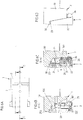
- a pair of magnetic elements 250, 251, 350, 351 are arranged on each base body 20, 30, which face each other with dissimilar magnetic poles and thus cause a magnetic force of attraction between the closure parts 2, 3.
- the attachment of the closure parts 2, 3 is magnetically supported by the magnetic elements 250, 251, 350, 351, so that the connection between the closure parts 2, 3 is at least largely automatically established.
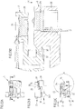
- a locking element 36 in the form of a lever element pivotable about a pivot axis 361 (see for example FIG Figure 4C ) arranged, which can be deflected from a basic position and serves to secure the closure parts 2, 3 to one another in their closed position, so that the engagement between the engagement projections 220, 221, 320, 321, 23, 33 is secured and not readily, at least not without Removal of the lock by the locking element 36 can be released.
- the locking element 36 engages in a locking opening 26 on the side of the other locking part 2, so that in this way the locking parts 2, 3 are secured to one another against the direction of engagement Y.
- an electrical contact element 24, 34 is arranged, which is used to establish electrical contact between the closure parts 2, 3 in the closed position of the closure device 1. In the closed position, the contact elements 24, 34 are in contact with one another in electrical contact so that a current can flow via the contact elements 24, 34.
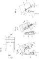
- FIGS 2A-2C to Figures 6A-6D show the closure device 1 during closing, that is, when the closure parts 2, 3 are attached to one another to close the closure device 1.
- the closure parts 2, 3 can be attached to one another in a closing direction X.
- the magnetic elements 250, 251, 350, 351 of the closure parts 2, 3 interact in a magnetically attracting manner, so that the closure parts 2, 3 are magnetically drawn towards one another when they approach.
- the magnet elements 250, 251, 350, 351 are arranged on the base bodies 20, 30 of the closure parts 2, 3 in such a way that the magnet elements 250, 251, 350, 351 are offset from one another in the closed position and one in the closed position as well as in the closed position magnetic attraction force (also) in the direction of the closed position, that is, in the direction of engagement of the engagement projections 220, 221, 320, 321, 23, 33 with one another.
- the locking element 36 which is pivotably arranged on the closure part 3, is deflected out of its basic position, as shown in FIG Figure 4C and 5C can be seen, due to an interaction of the closure part 2 with the locking element 36.
- the deflection of the locking element 36 from the basic position takes place against a pretensioning effect of a spring element 37, as shown in FIG Figure 4B It can be seen that a spring-mechanical tension acts on the locking element 36 in the direction of the basic position.
- the closing position of the closing parts 2, 3 is reached, the blocking element 36 is returned to the basic position and comes into engagement with the blocking opening 26 on the closing part 2, as is the case Figure 6C can be seen.
- the locking element 36 is arranged on the closure parts 3 in the immediate vicinity of the engagement device 32, so that the form fit between the closure parts 2, 3 is secured where the form fit engagement exists. This improves the mechanical hold of the closure parts 2, 3 on one another.
- Figures 7A-7D through 12A-12D such as Figures 13A-13D through 17A-17D show the closing of the closure device 1 when the closure parts 2, 3 are attached to one another at an angle (the direction of inclination of the closure part 3 with respect to the closure part 2 being reversed in the sequences of the figures).
- the advantageous combination of the angled engagement projections 220, 221, 320, 321, the locking element 36 arranged in the vicinity of these engagement projections and the straight engagement projections 23, 33 ensures that there is no misalignment, ie that only one group of engagement projections does not accidentally engage and the locking element engages.
- the angled engagement projections 220, 221, 320, 321 can also be formed by functionally identical, arc-shaped engagement projections.
- the contact elements 24, 34 slide one above the other even when the closure parts 2, 3 are placed on one another at an angle, when the engagement projections 220, 221, 320, 321, 23, 33 come into engagement with one another and before the closed position is established, as shown in FIG Figure 11C and 16C can be seen. Again, the connection of the closure parts 2, 3 is thus established by grinding the contact elements 24, 34 over one another.
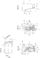
- the locking element 36 can be moved out of its engagement with the locking opening 26 via an actuating handle 360, so that the locking between the locking parts 2, 3 is canceled and the locking parts 2, 3 are removed from their engagement opposite the direction of engagement Y positive engagement can be solved.
- the closure parts 2, 3 By sliding the locking parts 2, 3 from each other against the direction of engagement Y (in an opening direction Z, see Figure 2C ) the closure parts 2, 3 can thus be separated from one another in order to release the assemblies assigned to the closure parts 2, 3.
- a guide element 31 on the closure part 3 also comes into engagement with a guide opening 21 on the other closure part 2.
- a linear guide of the closure parts 2, 3 is provided along the engagement direction Y against one another so that when placed of the closure parts 2, 3 against one another, the closure parts 2, 3 are guided to one another along the engagement direction Y and are thus fixed to one another in particular transversely to the engagement direction Y.
- an engagement element 230 is formed on the closure part 2, as shown for example in FIG Figure 31A and Figure 33B can be seen.
- the engagement element 230 is assigned an engagement opening 330 on the engagement projection 33 of the other closure part 3 (see FIG Figure 33B ), so that in the closed position of the locking device 1, shown in Figures 34A, 34B , via the engagement of the engagement element 230 in the engagement opening 330, the closure parts 2, 3 are additionally fixed transversely to the engagement direction Y to one another.
- a locking device 1 of the type described can serve to connect any number of assemblies to one another.
- the assemblies are mechanically firmly connected to one another, with simultaneous electrical contact between the locking parts 2, 3, so that, for example, an energy supply / energy transmission can be provided between the assemblies.
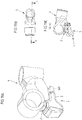
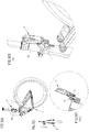
- the locking device 1 is used to attach a bicycle light to a bicycle and is correspondingly assigned to a holder 4, which can connect, for example, a handlebar of a bicycle to a front fork via fastening openings 40, 41.
- the closure part 2 is attached to the holder 4, while the other closure part 3 is assigned to the bicycle light.
- the bicycle light can be attached to the holder 4 and thus to the bicycle, with simultaneous electrical contact, for example for the purpose of supplying the bicycle light with electricity.
- the actuation handle 360 can be operated in order in this way to cancel the position between the closure parts 2, 3, so that the bicycle light, as shown in FIG Figures 21A-21D is shown, can be released from the holder 4.
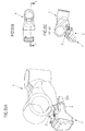
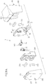
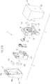
- the locking device 1 can also serve to connect other assemblies of a bicycle, for example also to connect a rear light 6 to a bicycle frame 50 of a bicycle 5, as shown in Figures 28A-28D through 30A-30D is shown. Again, the locking device 1 is used to produce a mechanical hold of the rear light 6 on the bicycle frame 50 and also for electrical contacting.
- a locking device can in particular also be designed without electrical contacts and thus serve for the purely mechanical-magnetic connection of two assemblies to one another.
- a locking device - with or without electrical contact elements - can be used to connect assemblies on a bicycle, but can also serve to connect any other assemblies to one another.
Landscapes
- Engineering & Computer Science (AREA)
- Mechanical Engineering (AREA)
- General Engineering & Computer Science (AREA)
- Buckles (AREA)
- Details Of Connecting Devices For Male And Female Coupling (AREA)
- Operating, Guiding And Securing Of Roll- Type Closing Members (AREA)
- Casings For Electric Apparatus (AREA)
Applications Claiming Priority (3)
| Application Number | Priority Date | Filing Date | Title |
|---|---|---|---|
| DE102017212149.1A DE102017212149A1 (de) | 2017-07-14 | 2017-07-14 | Verschlussvorrichtung mit elektrischem Kontakt |
| EP18746583.6A EP3652811B1 (fr) | 2017-07-14 | 2018-07-06 | Dispositif de fermeture |
| PCT/EP2018/068438 WO2019011819A1 (fr) | 2017-07-14 | 2018-07-06 | Dispositif de fermeture avec contact électrique |
Related Parent Applications (2)
| Application Number | Title | Priority Date | Filing Date |
|---|---|---|---|
| EP18746583.6A Division-Into EP3652811B1 (fr) | 2017-07-14 | 2018-07-06 | Dispositif de fermeture |
| EP18746583.6A Division EP3652811B1 (fr) | 2017-07-14 | 2018-07-06 | Dispositif de fermeture |
Publications (2)
| Publication Number | Publication Date |
|---|---|
| EP3780288A1 true EP3780288A1 (fr) | 2021-02-17 |
| EP3780288B1 EP3780288B1 (fr) | 2025-10-15 |
Family
ID=63041960
Family Applications (2)
| Application Number | Title | Priority Date | Filing Date |
|---|---|---|---|
| EP20195515.0A Active EP3780288B1 (fr) | 2017-07-14 | 2018-07-06 | Dispositif de fermeture à contact électrique |
| EP18746583.6A Active EP3652811B1 (fr) | 2017-07-14 | 2018-07-06 | Dispositif de fermeture |
Family Applications After (1)
| Application Number | Title | Priority Date | Filing Date |
|---|---|---|---|
| EP18746583.6A Active EP3652811B1 (fr) | 2017-07-14 | 2018-07-06 | Dispositif de fermeture |
Country Status (6)
| Country | Link |
|---|---|
| US (1) | US11245223B2 (fr) |
| EP (2) | EP3780288B1 (fr) |
| CN (1) | CN110892591B (fr) |
| DE (1) | DE102017212149A1 (fr) |
| ES (1) | ES2896310T3 (fr) |
| WO (1) | WO2019011819A1 (fr) |
Families Citing this family (4)
| Publication number | Priority date | Publication date | Assignee | Title |
|---|---|---|---|---|
| CN111934126A (zh) * | 2020-08-13 | 2020-11-13 | 刘培秀 | 一种卡扣式磁吸端子 |
| EP4013256B1 (fr) | 2020-11-05 | 2023-02-22 | Cardo Systems, Ltd. | Dispositif de fixation magnétique |
| US12103660B2 (en) | 2022-02-02 | 2024-10-01 | Textron Innovations Inc. | Aircraft stair system including deployable table |
| DE102024118817B3 (de) * | 2024-07-02 | 2025-11-20 | Fidlock Gmbh | Verbinderbaugruppe und Verbinderbauteil |
Citations (9)
| Publication number | Priority date | Publication date | Assignee | Title |
|---|---|---|---|---|
| FR2638907A1 (fr) * | 1988-11-04 | 1990-05-11 | Dalmau Raymond | Dispositif ameliore relatif a l'utilisation de l'attraction magnetique et au positionnement des contacts electriques dans la connexion d'une ampoule et d'une douille |
| KR960009916Y1 (ko) | 1994-01-17 | 1996-11-19 | 김한기 | 지퍼용 탈피기 |
| DE4312032C2 (de) | 1992-04-14 | 1997-04-17 | Rixen & Kaul Gmbh | Kupplung zum Befestigen und Lösen von Ausrüstungsgegenständen |
| EP1220369A1 (fr) * | 2001-01-02 | 2002-07-03 | Furas S.A. | Connecteur de sécurité pour un appareil ménager électrique pour le plateau de table |
| WO2008068241A1 (fr) * | 2006-12-04 | 2008-06-12 | Pilkington Automotive Deutschland Gmbh | Connecteur |
| US20090215283A1 (en) | 2008-02-21 | 2009-08-27 | Hong Fu Jin Precision Industry (Shenzhen) Co., Ltd. | Connector |
| WO2014090926A1 (fr) * | 2012-12-14 | 2014-06-19 | Fidlock Gmbh | Dispositif de fermeture pour relier deux pièces de manière détachable |
| EP2955092A1 (fr) * | 2012-10-30 | 2015-12-16 | Bonopark, S.L. | Système d'ancrage et de recharge pour bicyclettes électriques de location |
| WO2016166538A1 (fr) * | 2015-04-15 | 2016-10-20 | Ab Connectors Ltd | Ensemble connecteur |
Family Cites Families (5)
| Publication number | Priority date | Publication date | Assignee | Title |
|---|---|---|---|---|
| JPS5315729B2 (fr) * | 1973-12-04 | 1978-05-26 | ||
| CN1178402A (zh) | 1996-08-09 | 1998-04-08 | 住友电装株式会社 | 电动汽车用充电连接器 |
| EP0977215A3 (fr) * | 1996-08-09 | 2000-12-06 | SUMITOMO WIRING SYSTEMS, Ltd. | Connecteur pour charger un véhicule électrique |
| US8920178B2 (en) * | 2011-12-01 | 2014-12-30 | Htc Corporation | Electronic apparatus assembly |
| AU2013389284B2 (en) | 2013-05-08 | 2018-08-09 | Fidlock Gmbh | Closure device |
-
2017
- 2017-07-14 DE DE102017212149.1A patent/DE102017212149A1/de not_active Withdrawn
-
2018
- 2018-07-06 ES ES18746583T patent/ES2896310T3/es active Active
- 2018-07-06 EP EP20195515.0A patent/EP3780288B1/fr active Active
- 2018-07-06 WO PCT/EP2018/068438 patent/WO2019011819A1/fr not_active Ceased
- 2018-07-06 CN CN201880046660.XA patent/CN110892591B/zh active Active
- 2018-07-06 US US16/630,760 patent/US11245223B2/en active Active
- 2018-07-06 EP EP18746583.6A patent/EP3652811B1/fr active Active
Patent Citations (9)
| Publication number | Priority date | Publication date | Assignee | Title |
|---|---|---|---|---|
| FR2638907A1 (fr) * | 1988-11-04 | 1990-05-11 | Dalmau Raymond | Dispositif ameliore relatif a l'utilisation de l'attraction magnetique et au positionnement des contacts electriques dans la connexion d'une ampoule et d'une douille |
| DE4312032C2 (de) | 1992-04-14 | 1997-04-17 | Rixen & Kaul Gmbh | Kupplung zum Befestigen und Lösen von Ausrüstungsgegenständen |
| KR960009916Y1 (ko) | 1994-01-17 | 1996-11-19 | 김한기 | 지퍼용 탈피기 |
| EP1220369A1 (fr) * | 2001-01-02 | 2002-07-03 | Furas S.A. | Connecteur de sécurité pour un appareil ménager électrique pour le plateau de table |
| WO2008068241A1 (fr) * | 2006-12-04 | 2008-06-12 | Pilkington Automotive Deutschland Gmbh | Connecteur |
| US20090215283A1 (en) | 2008-02-21 | 2009-08-27 | Hong Fu Jin Precision Industry (Shenzhen) Co., Ltd. | Connector |
| EP2955092A1 (fr) * | 2012-10-30 | 2015-12-16 | Bonopark, S.L. | Système d'ancrage et de recharge pour bicyclettes électriques de location |
| WO2014090926A1 (fr) * | 2012-12-14 | 2014-06-19 | Fidlock Gmbh | Dispositif de fermeture pour relier deux pièces de manière détachable |
| WO2016166538A1 (fr) * | 2015-04-15 | 2016-10-20 | Ab Connectors Ltd | Ensemble connecteur |
Also Published As
| Publication number | Publication date |
|---|---|
| EP3652811A1 (fr) | 2020-05-20 |
| EP3652811B1 (fr) | 2021-09-01 |
| EP3780288B1 (fr) | 2025-10-15 |
| US11245223B2 (en) | 2022-02-08 |
| DE102017212149A1 (de) | 2019-01-17 |
| CN110892591A (zh) | 2020-03-17 |
| WO2019011819A1 (fr) | 2019-01-17 |
| ES2896310T3 (es) | 2022-02-24 |
| CN110892591B (zh) | 2022-03-29 |
| US20200235520A1 (en) | 2020-07-23 |
Similar Documents
| Publication | Publication Date | Title |
|---|---|---|
| DE102020207107B4 (de) | Magnetische schnallenbaugruppe | |
| EP3652811B1 (fr) | Dispositif de fermeture | |
| DE69311012T2 (de) | Elektrischer Verbinder | |
| EP3220781B1 (fr) | Dispositif de fermeture permettant de fixer un appareil électronique à un dispositif de retenue | |
| DE69737280T2 (de) | Gehäuse angepasst an ein Lagesicherungssystem für einen elektrischen Verbinder | |
| EP2833754B1 (fr) | Dispositif de fermeture pour relier deux pièces de manière détachable | |
| DE60309100T2 (de) | Vorrichtung zur Lagesicherung eines Verbinders | |
| DE69411224T2 (de) | Verbindereinrichtung | |
| EP3066724B1 (fr) | Connecteur enfichable push-pull muni d'un élément de verrouillage supplémentaire | |
| DE102014101952B4 (de) | Steckverbinderteil mit einem Rastelement | |
| EP3652399B1 (fr) | Dispositif de fermeture | |
| DE10308321A1 (de) | Verbinder und Verbinderanordnung | |
| WO2010084191A1 (fr) | Dispositif de fermeture destiné à relier deux pièces | |
| DE2140039B2 (de) | Steckvorrichtung fur eine elek trische Leitungsverbindung | |
| DE2730115A1 (de) | Magnetverschluss | |
| EP4277489B1 (fr) | Dispositif de fermeture mécanique magnétique | |
| DE3818092C2 (fr) | ||
| DE602005000836T2 (de) | Elektrischer Steckverbinder | |
| DE102006024963A1 (de) | Verbinder vom Hebeltyp | |
| DE102004019994B4 (de) | Verbinder | |
| DE19532623B4 (de) | Elektrischer Stecker mit einem Betätigungsschieber | |
| DE102022206462B3 (de) | Haltevorrichtung zum Halten eines Gegenstands an einer Baugruppe | |
| DE69223513T2 (de) | Verschluss | |
| DE102024118802B4 (de) | Verbinderbaugruppe mit verstellbarem Kontaktabschnitt für eine elektrische Kontaktierung | |
| DE102011119442A1 (de) | Vorrichtung zur Halterung von Identifikationskarten |
Legal Events
| Date | Code | Title | Description |
|---|---|---|---|
| PUAI | Public reference made under article 153(3) epc to a published international application that has entered the european phase |
Free format text: ORIGINAL CODE: 0009012 |
|
| STAA | Information on the status of an ep patent application or granted ep patent |
Free format text: STATUS: THE APPLICATION HAS BEEN PUBLISHED |
|
| AC | Divisional application: reference to earlier application |
Ref document number: 3652811 Country of ref document: EP Kind code of ref document: P |
|
| AK | Designated contracting states |
Kind code of ref document: A1 Designated state(s): AL AT BE BG CH CY CZ DE DK EE ES FI FR GB GR HR HU IE IS IT LI LT LU LV MC MK MT NL NO PL PT RO RS SE SI SK SM TR |
|
| STAA | Information on the status of an ep patent application or granted ep patent |
Free format text: STATUS: REQUEST FOR EXAMINATION WAS MADE |
|
| 17P | Request for examination filed |
Effective date: 20210812 |
|
| RBV | Designated contracting states (corrected) |
Designated state(s): AL AT BE BG CH CY CZ DE DK EE ES FI FR GB GR HR HU IE IS IT LI LT LU LV MC MK MT NL NO PL PT RO RS SE SI SK SM TR |
|
| STAA | Information on the status of an ep patent application or granted ep patent |
Free format text: STATUS: EXAMINATION IS IN PROGRESS |
|
| 17Q | First examination report despatched |
Effective date: 20230224 |
|
| GRAP | Despatch of communication of intention to grant a patent |
Free format text: ORIGINAL CODE: EPIDOSNIGR1 |
|
| STAA | Information on the status of an ep patent application or granted ep patent |
Free format text: STATUS: GRANT OF PATENT IS INTENDED |
|
| INTG | Intention to grant announced |
Effective date: 20250516 |
|
| RIN1 | Information on inventor provided before grant (corrected) |
Inventor name: FIEDLER, JOACHIM Inventor name: SIEBERT, ARTUR Inventor name: HILLER, LASSE |
|
| GRAS | Grant fee paid |
Free format text: ORIGINAL CODE: EPIDOSNIGR3 |
|
| GRAA | (expected) grant |
Free format text: ORIGINAL CODE: 0009210 |
|
| STAA | Information on the status of an ep patent application or granted ep patent |
Free format text: STATUS: THE PATENT HAS BEEN GRANTED |
|
| AC | Divisional application: reference to earlier application |
Ref document number: 3652811 Country of ref document: EP Kind code of ref document: P |
|
| AK | Designated contracting states |
Kind code of ref document: B1 Designated state(s): AL AT BE BG CH CY CZ DE DK EE ES FI FR GB GR HR HU IE IS IT LI LT LU LV MC MK MT NL NO PL PT RO RS SE SI SK SM TR |
|
| P01 | Opt-out of the competence of the unified patent court (upc) registered |
Free format text: CASE NUMBER: UPC_APP_6403_3780288/2025 Effective date: 20250909 |
|
| REG | Reference to a national code |
Ref country code: GB Ref legal event code: FG4D Free format text: NOT ENGLISH Ref country code: CH Ref legal event code: F10 Free format text: ST27 STATUS EVENT CODE: U-0-0-F10-F00 (AS PROVIDED BY THE NATIONAL OFFICE) Effective date: 20251015 |
|
| REG | Reference to a national code |
Ref country code: IE Ref legal event code: FG4D Free format text: LANGUAGE OF EP DOCUMENT: GERMAN |
|
| REG | Reference to a national code |
Ref country code: DE Ref legal event code: R096 Ref document number: 502018016162 Country of ref document: DE |
|
| REG | Reference to a national code |
Ref country code: NL Ref legal event code: MP Effective date: 20251015 |
|
| PG25 | Lapsed in a contracting state [announced via postgrant information from national office to epo] |
Ref country code: NL Free format text: LAPSE BECAUSE OF FAILURE TO SUBMIT A TRANSLATION OF THE DESCRIPTION OR TO PAY THE FEE WITHIN THE PRESCRIBED TIME-LIMIT Effective date: 20251015 |
|
| PG25 | Lapsed in a contracting state [announced via postgrant information from national office to epo] |
Ref country code: ES Free format text: LAPSE BECAUSE OF FAILURE TO SUBMIT A TRANSLATION OF THE DESCRIPTION OR TO PAY THE FEE WITHIN THE PRESCRIBED TIME-LIMIT Effective date: 20251015 |
|
| REG | Reference to a national code |
Ref country code: LT Ref legal event code: MG9D |
|
| PG25 | Lapsed in a contracting state [announced via postgrant information from national office to epo] |
Ref country code: NO Free format text: LAPSE BECAUSE OF FAILURE TO SUBMIT A TRANSLATION OF THE DESCRIPTION OR TO PAY THE FEE WITHIN THE PRESCRIBED TIME-LIMIT Effective date: 20260115 |
|
| PG25 | Lapsed in a contracting state [announced via postgrant information from national office to epo] |
Ref country code: FI Free format text: LAPSE BECAUSE OF FAILURE TO SUBMIT A TRANSLATION OF THE DESCRIPTION OR TO PAY THE FEE WITHIN THE PRESCRIBED TIME-LIMIT Effective date: 20251015 Ref country code: HR Free format text: LAPSE BECAUSE OF FAILURE TO SUBMIT A TRANSLATION OF THE DESCRIPTION OR TO PAY THE FEE WITHIN THE PRESCRIBED TIME-LIMIT Effective date: 20251015 |
|
| PG25 | Lapsed in a contracting state [announced via postgrant information from national office to epo] |
Ref country code: RS Free format text: LAPSE BECAUSE OF FAILURE TO SUBMIT A TRANSLATION OF THE DESCRIPTION OR TO PAY THE FEE WITHIN THE PRESCRIBED TIME-LIMIT Effective date: 20260115 |
|
| PG25 | Lapsed in a contracting state [announced via postgrant information from national office to epo] |
Ref country code: IS Free format text: LAPSE BECAUSE OF FAILURE TO SUBMIT A TRANSLATION OF THE DESCRIPTION OR TO PAY THE FEE WITHIN THE PRESCRIBED TIME-LIMIT Effective date: 20260215 |