EP3780311A1 - Leistungswandlungssystem - Google Patents
Leistungswandlungssystem Download PDFInfo
- Publication number
- EP3780311A1 EP3780311A1 EP19785119.9A EP19785119A EP3780311A1 EP 3780311 A1 EP3780311 A1 EP 3780311A1 EP 19785119 A EP19785119 A EP 19785119A EP 3780311 A1 EP3780311 A1 EP 3780311A1
- Authority
- EP
- European Patent Office
- Prior art keywords
- voltage
- power
- converter
- current
- command value
- Prior art date
- Legal status (The legal status is an assumption and is not a legal conclusion. Google has not performed a legal analysis and makes no representation as to the accuracy of the status listed.)
- Pending
Links
Images





Classifications
-
- H—ELECTRICITY
- H02—GENERATION; CONVERSION OR DISTRIBUTION OF ELECTRIC POWER
- H02J—ELECTRIC POWER NETWORKS; CIRCUIT ARRANGEMENTS OR SYSTEMS FOR SUPPLYING OR DISTRIBUTING ELECTRIC POWER; SYSTEMS FOR STORING ELECTRIC ENERGY
- H02J3/00—Circuit arrangements for AC mains or AC distribution networks
- H02J3/36—Arrangements for transfer of electric power between AC networks via high-voltage DC [HVDC] links; Arrangements for transfer of electric power between generators and networks via HVDC links
-
- H—ELECTRICITY
- H02—GENERATION; CONVERSION OR DISTRIBUTION OF ELECTRIC POWER
- H02H—EMERGENCY PROTECTIVE CIRCUIT ARRANGEMENTS
- H02H7/00—Emergency protective circuit arrangements specially adapted for specific types of electric machines or apparatus or for sectionalised protection of cable or line systems, and effecting automatic switching in the event of an undesired change from normal working conditions
- H02H7/06—Emergency protective circuit arrangements specially adapted for specific types of electric machines or apparatus or for sectionalised protection of cable or line systems, and effecting automatic switching in the event of an undesired change from normal working conditions for dynamo-electric generators; for synchronous capacitors
- H02H7/062—Emergency protective circuit arrangements specially adapted for specific types of electric machines or apparatus or for sectionalised protection of cable or line systems, and effecting automatic switching in the event of an undesired change from normal working conditions for dynamo-electric generators; for synchronous capacitors for parallel connected generators
-
- H—ELECTRICITY
- H02—GENERATION; CONVERSION OR DISTRIBUTION OF ELECTRIC POWER
- H02J—ELECTRIC POWER NETWORKS; CIRCUIT ARRANGEMENTS OR SYSTEMS FOR SUPPLYING OR DISTRIBUTING ELECTRIC POWER; SYSTEMS FOR STORING ELECTRIC ENERGY
- H02J1/00—Circuit arrangements for DC mains or DC distribution networks
- H02J1/002—Circuit arrangements for DC mains or DC distribution networks using intermediate DC-AC-DC conversion
-
- H—ELECTRICITY
- H02—GENERATION; CONVERSION OR DISTRIBUTION OF ELECTRIC POWER
- H02J—ELECTRIC POWER NETWORKS; CIRCUIT ARRANGEMENTS OR SYSTEMS FOR SUPPLYING OR DISTRIBUTING ELECTRIC POWER; SYSTEMS FOR STORING ELECTRIC ENERGY
- H02J3/00—Circuit arrangements for AC mains or AC distribution networks
- H02J3/38—Arrangements for feeding a single network from two or more generators or sources in parallel; Arrangements for feeding already energised networks from additional generators or sources in parallel
-
- H—ELECTRICITY
- H02—GENERATION; CONVERSION OR DISTRIBUTION OF ELECTRIC POWER
- H02J—ELECTRIC POWER NETWORKS; CIRCUIT ARRANGEMENTS OR SYSTEMS FOR SUPPLYING OR DISTRIBUTING ELECTRIC POWER; SYSTEMS FOR STORING ELECTRIC ENERGY
- H02J3/00—Circuit arrangements for AC mains or AC distribution networks
- H02J3/38—Arrangements for feeding a single network from two or more generators or sources in parallel; Arrangements for feeding already energised networks from additional generators or sources in parallel
- H02J3/381—Dispersed generators
-
- H—ELECTRICITY
- H02—GENERATION; CONVERSION OR DISTRIBUTION OF ELECTRIC POWER
- H02M—APPARATUS FOR CONVERSION BETWEEN AC AND AC, BETWEEN AC AND DC, OR BETWEEN DC AND DC, AND FOR USE WITH MAINS OR SIMILAR POWER SUPPLY SYSTEMS; CONVERSION OF DC OR AC INPUT POWER INTO SURGE OUTPUT POWER; CONTROL OR REGULATION THEREOF
- H02M1/00—Details of apparatus for conversion
- H02M1/32—Means for protecting converters other than automatic disconnection
-
- H—ELECTRICITY
- H02—GENERATION; CONVERSION OR DISTRIBUTION OF ELECTRIC POWER
- H02M—APPARATUS FOR CONVERSION BETWEEN AC AND AC, BETWEEN AC AND DC, OR BETWEEN DC AND DC, AND FOR USE WITH MAINS OR SIMILAR POWER SUPPLY SYSTEMS; CONVERSION OF DC OR AC INPUT POWER INTO SURGE OUTPUT POWER; CONTROL OR REGULATION THEREOF
- H02M3/00—Conversion of DC power input into DC power output
- H02M3/22—Conversion of DC power input into DC power output with intermediate conversion into AC
- H02M3/24—Conversion of DC power input into DC power output with intermediate conversion into AC by static converters
- H02M3/28—Conversion of DC power input into DC power output with intermediate conversion into AC by static converters using discharge tubes with control electrode or semiconductor devices with control electrode to produce the intermediate AC
- H02M3/325—Conversion of DC power input into DC power output with intermediate conversion into AC by static converters using discharge tubes with control electrode or semiconductor devices with control electrode to produce the intermediate AC using devices of a triode or a transistor type requiring continuous application of a control signal
- H02M3/335—Conversion of DC power input into DC power output with intermediate conversion into AC by static converters using discharge tubes with control electrode or semiconductor devices with control electrode to produce the intermediate AC using devices of a triode or a transistor type requiring continuous application of a control signal using semiconductor devices only
- H02M3/33569—Conversion of DC power input into DC power output with intermediate conversion into AC by static converters using discharge tubes with control electrode or semiconductor devices with control electrode to produce the intermediate AC using devices of a triode or a transistor type requiring continuous application of a control signal using semiconductor devices only having several active switching elements
- H02M3/33576—Conversion of DC power input into DC power output with intermediate conversion into AC by static converters using discharge tubes with control electrode or semiconductor devices with control electrode to produce the intermediate AC using devices of a triode or a transistor type requiring continuous application of a control signal using semiconductor devices only having several active switching elements having at least one active switching element at the secondary side of an isolation transformer
-
- H—ELECTRICITY
- H02—GENERATION; CONVERSION OR DISTRIBUTION OF ELECTRIC POWER
- H02M—APPARATUS FOR CONVERSION BETWEEN AC AND AC, BETWEEN AC AND DC, OR BETWEEN DC AND DC, AND FOR USE WITH MAINS OR SIMILAR POWER SUPPLY SYSTEMS; CONVERSION OF DC OR AC INPUT POWER INTO SURGE OUTPUT POWER; CONTROL OR REGULATION THEREOF
- H02M7/00—Conversion of AC power input into DC power output; Conversion of DC power input into AC power output
- H02M7/02—Conversion of AC power input into DC power output without possibility of reversal
- H02M7/04—Conversion of AC power input into DC power output without possibility of reversal by static converters
- H02M7/06—Conversion of AC power input into DC power output without possibility of reversal by static converters using discharge tubes without control electrode or semiconductor devices without control electrode
-
- H—ELECTRICITY
- H02—GENERATION; CONVERSION OR DISTRIBUTION OF ELECTRIC POWER
- H02M—APPARATUS FOR CONVERSION BETWEEN AC AND AC, BETWEEN AC AND DC, OR BETWEEN DC AND DC, AND FOR USE WITH MAINS OR SIMILAR POWER SUPPLY SYSTEMS; CONVERSION OF DC OR AC INPUT POWER INTO SURGE OUTPUT POWER; CONTROL OR REGULATION THEREOF
- H02M7/00—Conversion of AC power input into DC power output; Conversion of DC power input into AC power output
- H02M7/42—Conversion of DC power input into AC power output without possibility of reversal
- H02M7/44—Conversion of DC power input into AC power output without possibility of reversal by static converters
- H02M7/48—Conversion of DC power input into AC power output without possibility of reversal by static converters using discharge tubes with control electrode or semiconductor devices with control electrode
-
- H—ELECTRICITY
- H02—GENERATION; CONVERSION OR DISTRIBUTION OF ELECTRIC POWER
- H02H—EMERGENCY PROTECTIVE CIRCUIT ARRANGEMENTS
- H02H3/00—Emergency protective circuit arrangements for automatic disconnection directly responsive to an undesired change from normal electric working condition with or without subsequent reconnection ; integrated protection
- H02H3/08—Emergency protective circuit arrangements for automatic disconnection directly responsive to an undesired change from normal electric working condition with or without subsequent reconnection ; integrated protection responsive to excess current
- H02H3/087—Emergency protective circuit arrangements for automatic disconnection directly responsive to an undesired change from normal electric working condition with or without subsequent reconnection ; integrated protection responsive to excess current for DC applications
-
- H—ELECTRICITY
- H02—GENERATION; CONVERSION OR DISTRIBUTION OF ELECTRIC POWER
- H02J—ELECTRIC POWER NETWORKS; CIRCUIT ARRANGEMENTS OR SYSTEMS FOR SUPPLYING OR DISTRIBUTING ELECTRIC POWER; SYSTEMS FOR STORING ELECTRIC ENERGY
- H02J2101/00—Supply or distribution of decentralised, dispersed or local electric power generation
- H02J2101/20—Dispersed power generation using renewable energy sources
- H02J2101/28—Wind energy
-
- H—ELECTRICITY
- H02—GENERATION; CONVERSION OR DISTRIBUTION OF ELECTRIC POWER
- H02M—APPARATUS FOR CONVERSION BETWEEN AC AND AC, BETWEEN AC AND DC, OR BETWEEN DC AND DC, AND FOR USE WITH MAINS OR SIMILAR POWER SUPPLY SYSTEMS; CONVERSION OF DC OR AC INPUT POWER INTO SURGE OUTPUT POWER; CONTROL OR REGULATION THEREOF
- H02M1/00—Details of apparatus for conversion
- H02M1/0067—Converter structures employing plural converter units, other than for parallel operation of the units on a single load
- H02M1/007—Plural converter units in cascade
-
- H—ELECTRICITY
- H02—GENERATION; CONVERSION OR DISTRIBUTION OF ELECTRIC POWER
- H02M—APPARATUS FOR CONVERSION BETWEEN AC AND AC, BETWEEN AC AND DC, OR BETWEEN DC AND DC, AND FOR USE WITH MAINS OR SIMILAR POWER SUPPLY SYSTEMS; CONVERSION OF DC OR AC INPUT POWER INTO SURGE OUTPUT POWER; CONTROL OR REGULATION THEREOF
- H02M3/00—Conversion of DC power input into DC power output
- H02M3/22—Conversion of DC power input into DC power output with intermediate conversion into AC
- H02M3/24—Conversion of DC power input into DC power output with intermediate conversion into AC by static converters
- H02M3/28—Conversion of DC power input into DC power output with intermediate conversion into AC by static converters using discharge tubes with control electrode or semiconductor devices with control electrode to produce the intermediate AC
- H02M3/325—Conversion of DC power input into DC power output with intermediate conversion into AC by static converters using discharge tubes with control electrode or semiconductor devices with control electrode to produce the intermediate AC using devices of a triode or a transistor type requiring continuous application of a control signal
- H02M3/335—Conversion of DC power input into DC power output with intermediate conversion into AC by static converters using discharge tubes with control electrode or semiconductor devices with control electrode to produce the intermediate AC using devices of a triode or a transistor type requiring continuous application of a control signal using semiconductor devices only
- H02M3/33569—Conversion of DC power input into DC power output with intermediate conversion into AC by static converters using discharge tubes with control electrode or semiconductor devices with control electrode to produce the intermediate AC using devices of a triode or a transistor type requiring continuous application of a control signal using semiconductor devices only having several active switching elements
- H02M3/33576—Conversion of DC power input into DC power output with intermediate conversion into AC by static converters using discharge tubes with control electrode or semiconductor devices with control electrode to produce the intermediate AC using devices of a triode or a transistor type requiring continuous application of a control signal using semiconductor devices only having several active switching elements having at least one active switching element at the secondary side of an isolation transformer
- H02M3/33584—Bidirectional converters
-
- H—ELECTRICITY
- H02—GENERATION; CONVERSION OR DISTRIBUTION OF ELECTRIC POWER
- H02M—APPARATUS FOR CONVERSION BETWEEN AC AND AC, BETWEEN AC AND DC, OR BETWEEN DC AND DC, AND FOR USE WITH MAINS OR SIMILAR POWER SUPPLY SYSTEMS; CONVERSION OF DC OR AC INPUT POWER INTO SURGE OUTPUT POWER; CONTROL OR REGULATION THEREOF
- H02M5/00—Conversion of AC power input into AC power output, e.g. for change of voltage, for change of frequency, for change of number of phases
- H02M5/40—Conversion of AC power input into AC power output, e.g. for change of voltage, for change of frequency, for change of number of phases with intermediate conversion into DC
- H02M5/42—Conversion of AC power input into AC power output, e.g. for change of voltage, for change of frequency, for change of number of phases with intermediate conversion into DC by static converters
- H02M5/44—Conversion of AC power input into AC power output, e.g. for change of voltage, for change of frequency, for change of number of phases with intermediate conversion into DC by static converters using discharge tubes or semiconductor devices to convert the intermediate DC into AC
- H02M5/453—Conversion of AC power input into AC power output, e.g. for change of voltage, for change of frequency, for change of number of phases with intermediate conversion into DC by static converters using discharge tubes or semiconductor devices to convert the intermediate DC into AC using devices of a triode or transistor type requiring continuous application of a control signal
- H02M5/458—Conversion of AC power input into AC power output, e.g. for change of voltage, for change of frequency, for change of number of phases with intermediate conversion into DC by static converters using discharge tubes or semiconductor devices to convert the intermediate DC into AC using devices of a triode or transistor type requiring continuous application of a control signal using semiconductor devices only
-
- Y—GENERAL TAGGING OF NEW TECHNOLOGICAL DEVELOPMENTS; GENERAL TAGGING OF CROSS-SECTIONAL TECHNOLOGIES SPANNING OVER SEVERAL SECTIONS OF THE IPC; TECHNICAL SUBJECTS COVERED BY FORMER USPC CROSS-REFERENCE ART COLLECTIONS [XRACs] AND DIGESTS
- Y02—TECHNOLOGIES OR APPLICATIONS FOR MITIGATION OR ADAPTATION AGAINST CLIMATE CHANGE
- Y02E—REDUCTION OF GREENHOUSE GAS [GHG] EMISSIONS, RELATED TO ENERGY GENERATION, TRANSMISSION OR DISTRIBUTION
- Y02E60/00—Enabling technologies; Technologies with a potential or indirect contribution to GHG emissions mitigation
- Y02E60/60—Arrangements for transfer of electric power between AC networks or generators via a high voltage DC link [HVCD]
Definitions
- the present invention relates to a power conversion system, and more particularly to a power conversion system that transmits alternating-current (AC) power generated by a power generator through a direct-current (DC) power grid to an AC power grid.
- AC alternating-current
- DC direct-current
- a DC power transmission system is known in which high-voltage DC power is transmitted between bulk power conversion devices interconnected with direct current.
- DC power transmission is advantageous over AC power transmission in that the DC power transmission is free from current loss caused by the skin effect and thus has lower transmission loss in long-distance power transmission. Further, DC power transmission is also advantageous because it requires only two power lines, whereas AC power transmission using three-phase power requires three power lines.
- DC power transmission which is suitable for bulk power transmission, is increasingly employed with the spread of renewable energy such as photovoltaic power generation or wind power generation.
- Japanese Patent Laying-Open No. 2016-1981 discloses a configuration of a DC power transmission system in which AC power generated in a power generation facility such as a wind power generation facility is converted by an AC/DC converter into DC power, which is then output to a DC collection grid and further raised by a DC/DC converter to a prescribed DC voltage for implementing DC power transmission through a power transmission line (DC power transmission grid). Furthermore, the DC power after DC power transmission is converted by a DC/AC converter into AC power, and thereafter, lowered by a transformer to a prescribed voltage and then supplied to AC devices.
- PTL 1 also discloses that the control mode is switched between a normal state and a fault state. Specifically, in the normal state, the DC/DC converter controls the voltage in the DC collection grid and the DC/AC converter controls the voltage in the DC power transmission grid. In contrast, at occurrence of an AC fault, the AC/DC converter controls the voltage in the DC collection grid and the DC/DC converter controls the voltage in the DC power transmission grid.
- An object of the present invention is to improve the operation continuity at occurrence of a short-time grid fault in a power conversion system that transmits AC power generated by a power generator through a DC power grid to an AC power grid.
- a power conversion system is a power conversion system that transmits AC power generated by a power generator through a DC power grid to an AC power grid.
- the power conversion system includes: an AC/DC power converter; a DC/DC power converter; and a control device to control the AC/DC power converter and the DC/DC power converter.
- the AC/DC power converter converts the AC power from the power generator into electric power of a first DC voltage, and outputs the electric power of the first DC voltage.
- the DC/DC power converter converts the electric power output from the AC/DC power converter into electric power of a second DC voltage, and outputs the electric power of the second DC voltage to the DC power grid.
- the control device includes a first drive control unit and a second drive control unit.
- the first drive control unit controls the AC/DC power converter such that an active current component and a reactive current component of an AC current output from the power generator follow an active current command value and a reactive current command value, respectively.
- the second drive control unit controls the DC/DC power converter such that the first DC voltage follows a DC voltage command value. Furthermore, when a fault occurs in the DC power grid or the AC power grid, the control device decreases at least one of the active current command value and the DC voltage command value in accordance with fluctuations of the second DC voltage, to suppress electric power that flows from the power generator into the AC/DC power converter.
- a control command value for an AC/DC power converter or a DC/DC power converter is adjusted so as to suppress incoming electric power flowing from the power generator in accordance with voltage fluctuations in the DC power grid.
- FIG. 1 is a block diagram illustrating the configuration of a power conversion system 100 according to the first embodiment.
- power conversion system 100 converts AC power generated by a plurality of wind power generation facilities 2A and 2B into DC power, collects electric power in the state of DC power, further steps up the collected DC power, and supplies AC power to an AC distribution grid 70.
- the number of wind power generation facilities connected to power conversion system 100 is two for convenience of illustration in FIG. 1 , but any number of wind power generation facilities may be connected to power conversion system 100.
- Wind power generation facilities 2A and 2B are installed on the sea or on a mountain, for example.
- Wind power generation facility 2A includes a windmill 10A and a power generator 20A coupled to a rotation shaft of windmill 10A.
- Wind power generation facility 2B includes a windmill 10B and a power generator 20B coupled to a rotation shaft of windmill 10B. Windmills 10A and 10B rotate so as to rotate respective rotors of power generators 20A and 20B, which then generate electric power to produce AC power.
- Power conversion system 100 includes a control device 1A, an AC/DC power converter 30A, a power line 31A, a first DC/DC power converter 40A, and a collection line 41A that correspond to wind power generation facility 2A.
- Power conversion system 100 also includes a control device 1B, an AC/DC power converter 30B, a power line 31B, a first DC/DC power converter 40B, and a collection line 41B that correspond to wind power generation facility 2B.
- Power conversion system 100 further includes a second DC/DC power converter 50, a power transmission line 51, and a DC/AC power converter 60.
- each of the AC/DC power converters, each of the DC/DC power converters, and each of the DC/AC power converters will be denoted simply as an AC/DC converter, a DC/DC converter, and a DC/AC converter, respectively.
- Control device 1A controls AC/DC converter 30A and first DC/DC converter 40A.
- Control device 1B controls AC/DC converter 30B and first DC/DC converter 40B.
- control devices for second DC/DC converter 50 and the DC/AC converter are further disposed.
- Control devices 1A and 1B each of which is representatively formed of a microcomputer, control the operations of AC/DC converter 30A and first DC/DC converter 40A and the operations of AC/DC converter 30B and first DC/DC converter 40B, respectively, by hardware processing by electronic circuits (not shown) incorporated therein and software processing by a central processing unit (CPU) (not shown) executing a program installed therein.
- CPU central processing unit
- AC/DC converters 30A and 30B convert three-phase AC power generated by respective power generators 20A and 20B into DC power, and output the converted DC power to power lines 31A and 31B, respectively.
- the DC power voltages on power lines 31A and 31B will also be referred to as "generated voltages VgnA and VgnB", respectively.
- First DC/DC converters 40A and 40B convert (step up) the DC power voltages (generated voltages VgnA and VgnB) converted by respective AC/DC converters 30A and 30B into different voltages, and output the converted voltages to respective collection lines 41A and 41B.
- Collection lines 41A and 41B are connected in parallel on the input side of second DC/DC converter 50 to thereby form a collection grid 45.
- Collection grid 45 collects DC power that is obtained by converting the electric power generated by wind power generation facilities 2A and 2B.
- the DC power voltage in collection grid 45 will be also referred to as a "collection voltage Vmdc”.
- Power conversion system 100 includes control devices 1A and 1B similarly configured, AC/DC converters 30A and 30B similarly configured, power lines 31A and 31B similarly configured, first DC/DC converters 40A and 40B similarly configured, and collection lines 41A and 41B similarly configured, which are disposed corresponding to respective wind power generation facilities 2A and 2B.
- These elements are denoted by reference numerals with suffixes A and B when the elements are distinguished from each other, whereas the elements are denoted by reference numerals with no suffix when the description is common to the elements.
- power conversion system 100 is provided with a pair of AC/DC converter 30 and first DC/DC converter 40 so as to correspond to each of wind power generation facilities 2A and 2B.
- DC power stepped-up by first DC/DC converter 40 is collected.
- second DC/DC converter 50 collects the collected DC power and further steps up the collected DC power for implementing high-voltage DC transmission (HVDC).
- HVDC high-voltage DC transmission
- the voltage of the DC power transmitted through power transmission line 51 (a DC power transmission grid) will be also referred to as a "transmission voltage Vhdc".
- the devices from AC/DC converter 30 to second DC/DC converter 50 are disposed in a conversion station adjacent to wind power generation facility 2 on the sea.
- the DC power converted by second DC/DC converter 50 is transmitted through power transmission line 51, for example, to land.
- the transmitted DC power is supplied to a DC/AC converter 60 installed in a conversion station on the land side.
- DC/AC converter 60 converts the DC power into AC power, and supplies the converted AC power to AC distribution grid 70.
- power lines 31A and 31B (31) correspond to one example of the "first DC line”
- collection lines 41A and 41B (41) correspond to one example of the "second DC line”
- collection grid 45 corresponds to one example of a "DC power grid”.
- a generated voltage Vgn corresponds to one example of the "first DC voltage”
- collection voltage Vmdc corresponds to the "second DC voltage”.
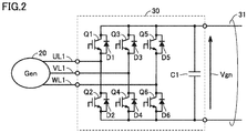
- FIG. 2 is a circuit diagram showing a configuration example of AC/DC converter 30 interconnected with power generator 20.
- AC/DC converter 30 includes: self-arc-extinguishing type semiconductor switching elements Q1 to Q6 that form a three-phase bridge circuit; diode elements D1 to D6 that are connected in antiparallel to semiconductor switching elements Q1 to Q6, respectively; and a smoothing capacitor C1.
- semiconductor switching elements Q1 to Q6 insulated gate bipolar transistors (IGBT) may be representatively applicable without being limited thereto, and other self-arc-extinguishing type semiconductor switching elements may also be applicable.
- Semiconductor switching elements Q1 to Q6 correspond to the "first semiconductor switching elements".
- the AC power generated by power generator 20 is supplied through power lines UL1, UV1, and UW1 to a three-phase bridge circuit of AC/DC converter 30 and then rectified.
- the DC power obtained by rectification is smoothed by smoothing capacitor C1 and supplied to power line 31.
- generated voltage Vgn is output from AC/DC converter 30 to this power line 31.
- FIG. 3 is a circuit diagram illustrating a detailed configuration example of first DC/DC converter 40.
- first DC/DC converter 40 has an insulation-type dual active bridge (DAB) configuration that includes: two self-excited and full bridge-type inverter circuits 111, 112; an insulating transformer (hereinafter simply referred to as a "transformer") TR1; and smoothing capacitors C11, C12.
- DAB insulation-type dual active bridge
- TR1 insulating transformer
- C11, C12 smoothing capacitors
- the DC/DC converter for high power transmission generally has a high-voltage circuit configuration formed of series-parallel connection of a plurality of DC/DC conversion circuits each having an insulation-type DAB configuration, but a circuit configured in one stage will be hereinafter described by way of example for simplification of description.
- Inverter circuit 111 includes: smoothing capacitor C11; semiconductor switching elements Q11 and Q12 connected in series; and semiconductor switching elements Q13 and Q14 connected in series, each of which is connected between power lines PL1 and NL1.
- Semiconductor switching elements Q11 to Q14 include diodes D11 to D14, respectively, that are connected in antiparallel thereto.
- Power lines PL1 and NL1 on the primary side of first DC/DC converter 40 (on the primary winding side of transformer TR1) are connected to power line 31 through which generated voltage Vgn is output from AC/DC converter 30.
- Inverter circuit 111 converts the DC power smoothed by smoothing capacitor C11 into AC power and outputs the converted AC power to transformer TR1. While ensuring electrical insulation, transformer TR1 transfers, to the secondary winding, the AC power supplied from inverter circuit 111 to the primary winding. The AC power of the secondary winding is input into inverter circuit 112.
- Inverter circuit 112 is basically similar in configuration to inverter circuit 111. Specifically, inverter circuit 112 includes: semiconductor switching elements Q15 and Q16 connected in series; semiconductor switching elements Q17 and Q18 connected in series; and smoothing capacitor C12, each of which is connected between power lines PL2 and NL2. Semiconductor switching elements Q15 to Q18 include diodes D15 to D18, respectively, that are connected in antiparallel thereto.
- Inverter circuit 112 charges and discharges smoothing capacitor C12 with the AC power supplied from transformer TR1 (on the secondary side) for smoothing, and then, outputs DC power (collection voltage Vmdc).
- Inverter circuits 111 and 112 each are not limited to a full bridge-type inverter but may be a three-level inverter, for example.
- FIG. 3 shows an example in which an IGBT is used as each of semiconductor switching elements Q11 to Q18 included in inverter circuits 111 and 112, but semiconductor switching elements Q11 to Q18 are not limited thereto and may be formed using other self-arc-extinguishing type semiconductor switching elements.
- Semiconductor switching elements Q11 to Q18 correspond to the "second semiconductor switching elements".
- First DC/DC converter 40 and second DC/DC converter 50 have the same basic hardware configuration.
- second DC converter 50 power lines PL1 and NL1 on the primary side are connected to a collection line 41 through which collection voltage Vmdc is output from first DC/DC converter 40.
- power lines PL2 and NL2 on the secondary side are connected to power transmission line 51 through which transmission voltage Vhdc is output.
- FIG. 4 is a block diagram illustrating the detailed configuration from a windmill 10 to second DC/DC converter 50 in the power conversion system according to the first embodiment.
- Collection lines 41A and 41B are provided with, as a protection device; DC reactors (DCL1A, DCL2A, DCL1B, DCL2B, DCL3, DCL4) for suppressing a fault current at occurrence of a DC line fault; DC circuit breakers (CB1A to CB4A, CB1B to CB4B); arresters (ARIA, AR2A, AR1B, AR2B) for protection from a surge voltage; and filters (FLA, FLB) for suppressing circuit resonance.
- DC reactors DCL1A, DCL2A, DCL1B, DCL2B, DCL3, DCL4
- DC circuit breakers CB1A to CB4A, CB1B to CB4B
- arresters ARIA, AR2A, AR1B, AR2B
- FLA, FLB filters
- a protection control device 3 Based on current detection values ICB3B and ICB4B by respective current detectors 65B and 66B disposed on collection line 41B, a protection control device 3 outputs control commands (OPCB3B, OPCB4B) for opening DC circuit breakers CB3B and CB4B, respectively, when a DC line short-circuit fault occurs.
- control commands OPCB3B, OPCB4B
- AC/DC converter 30B and DC/DC converter 40B are stopped while the operation is continued by control device 1A for AC/DC converter 30A and DC/DC converter 40A that are interconnected with a sound path (collection line) 41A.
- current detectors 65A and 65B are disposed in the same manner as current detectors 65B and 66B.
- occurrence of a DC line short-circuit fault (DC grid fault) on collection line 41A can be detected in the same manner as on collection line 41.
- DC circuit breakers CB3A and CB4A are opened.
- DC circuit breakers CB3A and CB4A do not detect a current in the reverse direction, so that the circuit breakers are not opened.
- control device 1A continues to control AC/DC converter 30A and DC/DC converter 40A.
- Control device 1A receives inputs of: current detection values IACA, IDC1A, and IDC2A by current detectors 61A, 63A, and 64A, respectively; and voltage detection values VgnA and VmdcA by voltage detectors 71A and 72A, respectively.
- Current detector 61A is disposed on the power lines (corresponding to UL1, VL1 and WL1 in FIG. 2 ) that connect power generator 20A and AC/DC converter 30A. Current detector 61A detects a generated current IACA by power generator 20A. Voltage detector 71A is connected to the primary side of first DC/DC converter 40A and detects a generated voltage VgnA. Current detectors 63A and 64A detect currents IDC1A and IDC2A, respectively, on the DC line (collection line 41A) on the secondary side of first DC/DC converter 40A. Voltage detector 72A is connected on collection line 41A to the end in close proximity to first DC/DC converter 40A and detects a collection voltage VmdcA.
- control device 1A Based on these current detection values IACA, IDC1A, IDC2A and voltage detection values VgnA, VmdcA, control device 1A outputs: a gate drive pulse signal PG ⁇ A for driving the semiconductor switching elements in first DC/DC converter 40A; and a gate drive signal SPWMA for driving the semiconductor switching elements in AC/DC converter 30A.
- control device 1B receives inputs of: current detection values IACB, IDC1B and IDC2B by current detectors 61B, 63B and 64B, respectively; and voltage detection values VgnB and VmdcB by voltage detectors 71B and 72B, respectively.
- Current detector 61B detects generated current IACB by power generator 20B in the same manner as current detector 61A.
- voltage detector 71B is connected to the primary side of first DC/DC converter 40B and detects generated voltage VgnB.
- current detectors 63A and 64A current detectors 63B and 64B detect currents IDC1B and IDC2B, respectively, on collection line 41B.
- voltage detector 72B is disposed on collection line 41B and detects collection voltage VmdcB.
- control device 1B Based on these current detection values IACB, IDC1B, IDC2B and voltage detection values VgnB, VmdcB, control device 1B outputs a gate drive pulse signal PG ⁇ B for driving the semiconductor switching elements in first DC/DC converter 40B and a gate drive signal SPWMB for driving the semiconductor switching elements in AC/DC converter 30B.
- inverter circuit 111 semiconductor switching elements Q11 and Q14 are turned on and off according to a first gate drive pulse signal PG ⁇ 1 while semiconductor switching elements Q12 and Q13 are turned on and off according to an inverted signal of first gate drive pulse signal PG ⁇ 1.
- semiconductor switching elements Q15 and Q18 are turned on and off according to a second gate drive pulse signal PG ⁇ 2 while semiconductor switching elements Q16 and Q17 are turned on and off according to an inverted signal of second gate drive pulse signal PG ⁇ 2.
- the above-mentioned gate drive pulse signal PG ⁇ A includes a first gate drive pulse signal PG ⁇ 1A and a second gate drive pulse signal PG ⁇ 2A in first DC/DC converter 40A.
- Gate drive pulse signal PG ⁇ B includes a first gate drive pulse signal PG ⁇ 1B and a second gate drive pulse signal PG ⁇ 2B in first DC/DC converter 40B.
- first gate drive pulse signal PG ⁇ 1 comprehensively represents first gate drive pulse signals PG ⁇ 1A and PG ⁇ 1B from first DC/DC converters 40A and 40B, respectively.
- Second gate drive pulse signal PG ⁇ 2 comprehensively represents second gate drive pulse signals PG ⁇ 2A and PG ⁇ 2B from first DC/DC converters 40A and 40B, respectively.
- each of first and second gate drive pulse signals PG ⁇ 1 and PG ⁇ 2 is fixed at the same frequency and at 50% of duty ratio, the phase of the gate drive pulse signal from inverter circuit 111 on the primary side is shifted with respect to the phase of the second gate drive pulse signal from inverter circuit 112 on the secondary side, thereby allowing control of generated voltage Vgn.
- second DC/DC converter 50 that can be configured in the manner similar to first DC/DC converter 40, switching of semiconductor switching elements Q11 to Q18 is controlled in the same manner as first DC/DC converter 40 to thereby change the phase difference of the gate drive pulse signals between inverter circuits 111 and 112. Thereby, collection voltage Vmdc on collection line 41 at the input end of second DC/DC converter 50 can be controlled.
- semiconductor switching elements Q1 to Q6 that form AC/DC converter 30 are turned on and off by pulse width modulation (PWM) control according to gate drive signals SPWMA and SPWMB shown in FIG. 5 .
- PWM pulse width modulation
- the command value of this PWM control is set to control the active current (AC current) supplied from power generator 20.
- power conversion system 100 includes one pair of AC/DC converter 30 and first DC/DC converter 40, and control device 1 for each of a plurality of wind power generation facilities 2.
- control devices 1A and 1B each of which corresponds to such AC/DC converter 30 and first DC/DC converter 40, each determine that the operation cannot be continued based on the voltage detection value and the current detection value at each interconnection point, and then, stops AC/DC converter 30 and first DC/DC converter 40.
- control device 1B stops AC/DC converter 30B and first DC/DC converter 40B.
- the operation is continued by control device 1A for AC/DC converter 30A and DC/DC converter 40A that are interconnected with a sound path (collection line) 41A.
- the FRT fault ride through
- the time taken for the voltage at the interconnection point to decease to 0V is set to be equal to or less than 140 ms.
- control device 1 controls AC/DC converter 30 and first DC/DC converter 40 at occurrence of a DC grid fault to stabilize the grid voltage speedily, thereby suppressing generation of an overvoltage and the like.
- the operation continuity can be improved.
- FIG. 5 is a control block diagram of AC/DC converter 30 and first DC/DC converter 40 controlled by control device 1.
- the control blocks of AC/DC converter 30 and first DC/DC converter 40 comprehensively shown in FIG. 5 are applicable in common to: control of AC/DC converter 30A and first DC/DC converter 40A; and control of AC/DC converter 30B and first DC/DC converter 40B.
- the function of each block in the configuration shown in FIG. 5 can be implemented by at least one of hardware processing and software processing by control device 1.
- control device 1 includes a DC voltage detection unit 83, a DC current detection unit 84, a voltage command value adjustment unit 89, a DC voltage control unit 93, a phase limiter 94, and a gate drive control unit 95, which serve as a functional block for controlling first DC/DC converter 40.
- Gate drive control unit 95 generates first and second gate drive pulse signals PG ⁇ 1 and PG ⁇ 2 of first DC/DC converter 40 for controlling generated voltage Vgn.
- DC voltage detection unit 83 detects generated voltage Vgn and collection voltage Vmdc based on the outputs from voltage detectors 71 and 72.
- Generated voltage Vgn is set based on: the voltage of smoothing capacitor C1 of AC/DC converter 30 (the synthesis value of the voltages of the smoothing capacitors in a multistage configuration); and the voltage of smoothing capacitor C11 on the primary side of first DC/DC converter 40 (the synthesis value of the voltages of the smoothing capacitors on the primary side in a multistage configuration).
- collection voltage Vmdc is set based on: the voltage of smoothing capacitor C12 on the secondary side of first DC/DC converter 40 (the synthesis value of the voltages of the smoothing capacitors on the secondary side in a multistage configuration); and the voltage of the smoothing capacitor (not shown) on the primary side of second DC/DC converter 50.
- current detectors 64 and 113 to 115 are further disposed in first DC/DC converter 40.
- Current detectors 113 and 114 are disposed on power line 31 at an end in close proximity to inverter circuit 111.
- Current detector 115 is disposed on the primary side of transformer TR1.
- Current detector 64 is disposed on the line on the lower voltage side of collection line 41 at an end in close proximity to inverter circuit 112.
- current detector 63 is disposed on the line on the lower voltage side of collection line 41.
- DC current detection unit 84 Based on the outputs from current detectors 63, 64 and 113 to 115, DC current detection unit 84 detects output currents IDC1, IDC2, input currents ILP1, ILN1, and a converter current IINV.
- Voltage command value adjustment unit 89 receives an input of a detection value of collection voltage Vmdc by DC voltage detection unit 83 and outputs a generated voltage command value Vgn_ref.
- generated voltage command value Vgn_ref is set as a predetermined rated value (a rated voltage) of the collection voltage.
- the upper limit of the normal operation voltage can be set to be about 110% of the above-mentioned rated voltage.
- voltage command value adjustment unit 89 sets generated voltage command value Vgn_ref to be lower than the above-mentioned rated value.
- the value (adjustment amount) obtained by multiplying the increase amount of collection voltage Vmdc with respect to the rated voltage (i.e., Vmdc - rated voltage) by K (K: a constant) is subtracted from the rated voltage, thereby allowing generated voltage command value Vgn_ref to be set.
- Generated voltage command value Vgn ref is output approximately in a range of 80% to 110% of the rated voltage in order to suppress fluctuations of the generated voltage caused by a sudden change in the command value.
- the electric power output from first DC/DC converter 40 can be calculated from the product of collection voltage Vmdc (voltage detector 72) and output current IDC1 (current detector 63). By feed forward of the electric power output from first DC/DC converter 40, the control response for collection voltage Vmdc can be enhanced.
- Phase difference ⁇ calculated by DC voltage control unit 93 is limited within a predetermined range (for example, equal to or less than ⁇ 60 degrees) by phase limiter 94.
- gate drive control unit 95 According to phase difference ⁇ obtained after passage through phase limiter 94, gate drive control unit 95 generates first gate drive pulse signal PG ⁇ 1 (inverter circuit 111) and second gate drive pulse signal PG ⁇ 2 (inverter circuit 112). Between first and second gate drive pulse signals PG ⁇ 1 and PG ⁇ 2 that are fixed at 50% of duty ratio and at the same frequency, phase difference ⁇ (after limitation by phase limiter 94) is provided. Specifically, phase difference ⁇ is subtracted from a reference phase ⁇ of second gate drive pulse signal PG ⁇ 2 in inverter circuit 112 to generate first gate drive pulse signal PG ⁇ 1.
- control device 1 includes an AC voltage detection unit 81, an AC current detection unit 82, a phase detection unit 85, a dq conversion unit 86, an AC voltage control unit 87, an active current command value adjustment unit 88, an active current command value limiter 97, an AC current control unit 90, a modulation factor limiter 91, and a gate drive control unit 92, which serve as a functional block for controlling AC/DC converter 30.
- Gate drive control unit 92 generates a gate drive signal SPWM (which comprehensively represent SPWMA and SPWMB) for AC/DC converter 30 for controlling an active current.
- AC voltage detection unit 81 detects the voltages (VU, VV, VW) in the respective phases (a U-phase, a V-phase, and a W-phase) of the three-phase AC power output from power generator 20.
- Phase detection unit 85 outputs a phase ⁇ of the output from the power generator based on the detection values of the three-phase AC voltages (VU, VV, VW).
- AC current detection unit 82 detects the phase currents (IU, IV and IW) of the three-phase AC power from power generator 20. Then, dq conversion unit 86 performs dq conversion of the three-phase voltages and the three-phase currents using the AC voltages (VU, VV, VW), the AC currents (IU, IV, IW), and phase ⁇ . Then, dq conversion unit 86 outputs a d-axis voltage Vd, a q-axis voltage Vq, a d-axis current Id, and a q-axis current Iq.
- AC voltage control unit 87 generates a reactive current command value Id_ref from the voltages (Vd, Vq) obtained by dq conversion.
- Active current command value adjustment unit 88 generates an active current command value Iq_ref based on generated voltage Vgn from DC voltage detection unit 83 and generated voltage command value Vgn_ref from voltage command value adjustment unit 89.
- the value (adjustment amount) obtained by multiplying, by h (h: a constant), the increase amount of generated voltage Vgn with respect to generated voltage command value Vgn_ref (Vgn - Vgn_ref) as a target value of generated voltage Vgn is subtracted from the predetermined active current command value in the normal state (in this case, the maximum value is 1 pu), thereby generating active current command value Iq_ref.
- Active current command value Iq_ref calculated by active current command value adjustment unit 88 is limited within a predetermined range (for example, 0% to 110% of the rated current) by active current command value limiter 97.
- PI proportional-integral
- Pulse width modulation factor MFpwm calculated by AC current control unit 90 is limited by modulation factor limiter 91 to fall within a predetermined range such that AC/DC converter 30 is controlled within the stable operation region.
- gate drive control unit 92 According to pulse width modulation factor MFpwm obtained after passage through modulation factor limiter 91, gate drive control unit 92 generates gate drive signal SPWM for driving semiconductor switching elements Q1 to Q6 in AC/DC converter 30.
- pulse width modulation factor MFpwm corresponds to one example of the "first control output”
- gate drive control unit 92 corresponds to one example of the "first gate drive control unit”.
- AC current control unit 90 and gate drive control unit 92 can form one example of the "first drive control unit".
- gate drive signal SPWM is generated so as to control turning on and off of the semiconductor switching elements in the U-phase (Q1, Q2), the V-phase (Q3, Q4), and the W-phase (Q5, Q6).
- the respective phase modulation waves mentioned above each are generated so as to have the same frequency as that of the generated electric power and to have an amplitude corresponding to the pulse width modulation factor.
- AC/DC converter 30 can control the active current supplied from power generator 20.
- AC/DC converter 30 controls the active current supplied from power generator 20 to power conversion system 100. Also, according to generated voltage command value Vgn_ref, first DC/DC converter 40 controls generated voltage Vgn (on power line 31).
- collection voltage Vmdc on collection line 41 is controlled by second DC/DC converter 50 while transmission voltage Vhdc on power transmission line 51 is controlled by DC/AC converter 60.
- control device 1 includes a converter protection control unit 96 for device protection from an overvoltage and an overcurrent.
- Converter protection control unit 96 outputs an OFF command for the gate signal when the DC voltage (Vmdc) detected by DC voltage detection unit 83 and the DC currents (IINV, ILP1, ILP2, IDC1, IDC2) detected by DC current detection unit 84 exceed their respective predetermined upper limit values.
- Vmdc DC voltage
- the gate block state of first DC/DC converter 40 is canceled (gate deblock) and semiconductor switching elements Q11 to Q18 are turned on and off according to first and second gate drive pulse signals PG ⁇ 1 and PG ⁇ 2 that are generated by gate drive control unit 95.
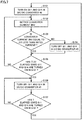
- control device 1 determines whether or not voltage detector 73 detects a decrease in collection voltage Vmdc at the end in close proximity to the secondary side of first DC/DC converter 40. For example, when collection voltage Vmdc decreases to be equal to or less than approximately 20% of the rated voltage, a "decrease in the collection voltage" is detected, and it is determined as YES in step S10. When a decrease in the collection voltage is detected, the process in and after step S20 is started to start the control process performed at occurrence of a DC grid fault.
- control device 1 determines whether at least one of output currents IDC1 and IDC2 from first DC/DC converter 40 by current detectors 63 and 64 exceeds a withstand current threshold value Imax or not. In other words, when at least one of
- a DC short-circuit fault occurs, normally, a short-circuit current flows into a fault point. Thus, a decrease in the collection voltage is detected in a short while in step S10, and thereafter, an overcurrent is detected.
- step S10 In the case where no overcurrent is detected even if a predetermined time period elapses since it is determined as YES in step S10, then, it is determined as NO in step S20. Further, in steps S30 and S40, AC/DC converter 30 and first DC/DC converter 40 each perform normal control. In other words, as described with reference to FIG. 5 , control (S30) of the DC voltage (generated voltage Vgn) by first DC/DC converter 40 and control (S40) of the active current by AC/DC converter 30 are performed.
- step S50 control device 1 sets first DC/DC converter 40 in a gate block state in order to prevent an overcurrent from flowing through each semiconductor switching element.
- step S50 converter protection control unit 96 ( FIG. 5 ) outputs an OFF command for a gate signal, thereby turning off each of semiconductor switching elements Q11 to Q18.
- first DC/DC converter 40 While first DC/DC converter 40 is in the gate block state, control of generated voltage Vgn by first DC/DC converter 40 is stopped and electric power flows in from power generator 20, with the result that generated voltage Vgn rises.
- control device 1 determines whether generated voltage Vgn detected by voltage detector 71 exceeds a normal operation range (approximately 110% of the rated voltage) or not. When generated voltage Vgn exceeds the normal operation range (when it is determined as YES in S60), then in step S70, control device 1 adjusts the active current command value for AC/DC converter 30. Specifically, active current command value adjustment unit 88 ( FIG.
- step S60 sets adjusted active current command value Iq_ref by subtracting the difference between generated voltage Vgn (Vgn ⁇ 1.1 pu) and the rated voltage of the generated voltage, i.e., the value (adjustment amount) corresponding to the increase amount of the generated voltage with respect to the rated voltage, from the active current command value (its maximum value is 1 pu in normal power transmission).
- the upper limit voltage (for example, 1.1 pu) in the normal operation range determined in step S60 corresponds to one example of the "first voltage".
- step S70 is skipped and the active current command value is not corrected.
- control device 1 performs feedback control of the active current of AC/DC converter 30 such that an active current Iq obtained by dq conversion of the three-phase AC currents (IU, IV, IW) detected by current detector 61 follows active current command value Iq_ref.
- the active current command value can be corrected to control the active current.
- the amount of incoming electric power flowing from power generator 20 can be suppressed to thereby suppress a rise in generated voltage Vgn.
- control device 1 causes first DC/DC converter 40 to autonomously control the collection voltage to rise again.
- the constant time period is set to fall within a time period satisfying the FRT requirements, which is approximately 20 [ms] to 100 [ms], for example.
- first DC/DC converter 40 can be started to autonomously control the collection voltage to rise again (S100).
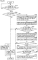
- FIG. 7 is a flowchart for illustrating details of the control process in step S100 for controlling the collection voltage to rise again.
- control device 1 turns on semiconductor switching elements Q11 and Q14 ( FIG. 3 ) in first DC/DC converter 40.
- control device 1 detects converter current IINV based on the output from current detector 115.
- control device 1 determines whether or not converter current IINV is equal to or less than the rated current on the primary side of first DC/DC converter 40.
- converter current IINV When converter current IINV is equal to or less than the rated current (when it is determined as YES in S103), semiconductor switching elements Q11 and Q14 each are maintained in the ON state. In contrast, when converter current IINV exceeds the rated current (when it is determined as NO in S103), semiconductor switching elements Q11 and Q14 are turned off in step S104.
- control device 1 determines whether a time period (T/2) corresponding to the half period of a predetermined switching period T has elapsed or not since semiconductor switching elements Q11 and Q14 are turned on in step S101. Until (T/2) elapses (when it is determined as NO in S105), semiconductor switching elements Q11 and Q14 are controlled to be turned on and off in steps S102 to S104.
- FIG. 8 shows a current path in first DC/DC converter 40 in control of the collection voltage to rise again.
- semiconductor switching elements Q11 and Q14 are turned on to form a current path on the primary side of transformer TR1. Thereby, electromotive force occurs also on the secondary side of transformer TR1. By this electromotive force, a current path caused by conduction of diodes D15 and D18 is formed on the secondary side of transformer TR1.
- an equivalent current path 300 is formed so as to extend in order of power line 31 (high voltage side) - semiconductor switching element Q11 - transformer TR1 - diode D15 -- smoothing capacitor C12 - diode D16 - transformer TR1 - semiconductor switching element Q14 - power line 31 (low voltage side), as indicated by a dotted line in the figure.
- smoothing capacitor C12 is charged while smoothing capacitor C11 ( FIG. 3 ) on the primary side of second DC/DC converter 50 is also charged.
- collection voltage Vmdc decreased due to the DC grid fault can be raised.
- control device 1 turns off semiconductor switching elements Q11 and Q14 in step S106. Thereby, semiconductor switching elements Q11 to Q14 are turned off. Furthermore, in step S107, it is determined whether switching period T has elapsed or not since semiconductor switching elements Q11 and Q14 are turned on in step S101. Then, semiconductor switching elements Q11 to Q14 each are kept in the OFF state (S106) until switching period T elapses.
- control device 1 When switching period T has elapsed (when it is determined as YES in S107), control device 1 returns the process to step S101. Thereby, the ON periods of semiconductor switching elements Q11 and Q14 can be controlled in a similar manner in each switching period T.
- the duty ratio at the time of ignition of semiconductor switching elements Q11 and Q14 is controlled to be equal to or less than 50 (%), and also adjusted to be within the range of 0 (%) to 50 (%) so as to keep converter current IINV to be equal to or less than the rated current.
- control device 1 determines in step S110 whether an overcurrent is detected or not, and determines in step S120 whether or not collection voltage Vmdc rises to be equal to or greater than 0.9 pu.
- Overcurrent detection in step S110 can be performed based on the determination similar to that in step S20.
- control device 1 determines that the grid (collection line 41B) having a DC line short-circuit fault is not interrupted. Then, control device 1 returns the process to step S50. Thereby, first DC/DC converter 40 is again set in a gate block state.
- control device 1 continuously causes first DC/DC converter 40 to control the collection voltage to rise again (S100) until collection voltage Vmdc rises to be equal to or greater than 0.9 pu (when it is determined as NO in S120).
- control device 1 When collection voltage Vmdc rises to be equal to or greater than 0.9 pu (when it is determined as YES in S120), control device 1 restarts the normal control by first DC/DC converter 40 in step S130. Thereby, power conversion system 100 returns from the operation for a fault performed upon overcurrent detection in and after step S50 to the normal power transmission operation under active current control by AC/DC converter 30 (S30) and generated voltage control by first DC/DC converter 40 (S40).
- the control of the collection voltage by first DC/DC converter 40 to rise again (S100) is autonomously started after a DC short-circuit fault occurs and before the information as to whether the fault path (collection line 41B in the example in FIG. 4 ) has been interrupted or not is obtained by communication from protection control device 3 ( FIG. 4 ).
- collection voltage Vmdc can be immediately recovered.
- overcurrent detection is performed in step S110.
- first DC/DC converter 40 autonomously allows the duty ratio to be variable so as to allow the collection voltage to rise again. Thereby, first DC/DC converter 40 can be immediately restarted at occurrence of a short-time grid fault, so that the operation continuity of the power conversion system can be improved.
- the configuration of power conversion system 100 and the control performed in the normal power transmission operation are the same as those in the first embodiment, and therefore, the detailed explanation thereof will not be repeated.
- FIG. 9 is a block diagram illustrating a point of occurrence of an AC grid fault described in the second embodiment.
- DC/AC converter 60 When DC/AC converter 60 stops, the target of voltage control by second DC/DC converter 40 is switched from collection voltage Vmdc on collection line 41 (the primary side) to transmission voltage Vhdc on power transmission line 51 (the secondary side). Thereby, the disturbance of transmission voltage Vhdc, i.e., HVDC grid voltage, can be suppressed. However, DC/AC converter 60 is stopped to thereby disallow transmission of electric power generated in wind power generation facility 2. Thus, electric power is excessively generated and the collection voltage rises.
- DC/AC converter 60 may not detect an overcurrent but may be continuously operated while controlling the transmission voltage in the normal operation range.
- transmission voltage Vhdc can be uniformly controlled by DC/AC converter 60.
- power transmission from DC/AC converter 60 to AC distribution grid 70 is however prohibited or limited by protection control in AC distribution grid 70.
- the collection voltage is to rise inside power conversion system 100. In this way, a fault occurring in AC distribution grid 70 causes a problem that the collection voltage rises inside power conversion system 100.
- FIG. 10 is a flowchart illustrating a control process performed at occurrence of an AC grid fault by a power conversion system according to the second embodiment.
- control device 1 determines whether or not voltage detector 72 detects a rise in collection voltage Vmdc at the end in close proximity to the secondary side of first DC/DC converter 40.
- the collection voltage rises when it is determined as YES in S210, it is determined in step S220 whether or not the detection value of collection voltage Vmdc is equal to or greater than 1.1 times (1.1 pu) as high as the rated voltage.
- the determination value (for example, 1.1 pu) in step S220 corresponds to one example of the "second voltage".
- control device 1 causes first DC/DC converter 40 to control generated voltage Vgn (the DC voltage on the primary side) in step S230 and causes AC/DC converter 30 to control the active current input from power generator 20 in step S240.
- control device 1 adjusts voltage command value Vgn ref of the DC voltage (generated voltage Vgn) on the primary side of first DC/DC converter 40.
- voltage command value adjustment unit 89 subtracts collection voltage Vmdc (detection value) and the value (adjustment amount) corresponding to the increase amount of the collection voltage with respect to the rated voltage (Vmdc - rated voltage) from the generated voltage command value (1.0 pu in the normal power transmission), to thereby set an adjusted generated voltage command value Vgn_ref.
- the above-mentioned adjustment amount can be calculated by multiplying, by a predetermined coefficient, the value obtained by subtracting the rated voltage from the detection value of collection voltage Vmdc.
- control device 1 causes first DC/DC converter 40 to perform feedback control of generated voltage Vgn according to generated voltage command value Vgn_ref adjusted in step S250.
- active current command value Iq_ref of AC/DC converter 30 is limited by active current command value limiter 97.
- active current command value Iq_ref is limited from increasing such that the electric power input from power generator 20 to power conversion system 100 is maintained uniformly even when generated voltage command value Vgn_ref is decreased.
- Vgn ref generated voltage command value
- Vmdc collection voltage
- DC/AC converter 60 is not stopped by an overcurrent.
- the voltage on the primary side (generated voltage Vgn) in first DC/DC converter 40 is controlled to be decreased to thereby suppress a rise in the collection voltage, so that power transmission can be continued.
- control device 1 detects a rise of the transmission voltage, and switches the target of voltage control by second DC/DC converter 50 from the collection voltage (on collection line 41) to the transmission voltage (on power transmission line 51) so as to suppress fluctuations of the transmission voltage. Such switching of the control target then causes a problem that a collection voltage rises.
- control device 1 detects a phenomenon in which: generated voltage command value Vgn_ref of first DC/DC converter 40 becomes equal to the lower limit value of the normal operation voltage (approximately 80% of the rated voltage); and collection voltage Vmdc detected by voltage detector 73 exceeds the normal operation range (approximately equal to or greater than 110% of the rated voltage).
- the lower limit value of the normal operation voltage determined in step S270 corresponds to one example of the "third voltage".
- control device 1 adjusts active current command value Iq_ref of AC/DC converter 30 in step S280. Specifically, as indicated by a dotted line in FIG. 5 , the detection value of collection voltage Vmdc is input to active current command value adjustment unit 88. Then, the value obtained by multiplying the difference between collection voltage Vmdc and the rated voltage of the collection voltage by a coefficient is subtracted from the active current command value in the normal state (in this case, the maximum value is 1 pu). Thereby, adjusted active current command value Iq_ref can be set.
- control device 1 causes AC/DC converter 30 to perform feedback control of the active current according to active current command value Iq_ref adjusted in step S280.
- control device 1 sets inverter circuit 112 on the secondary side of first DC/DC converter 40 in a gate block state. In other words, semiconductor switching elements Q15 to Q18 in FIG. 3 are turned off.
- Control device 1 keeps the gate block state set in step S310 until it is determined in step S320 that a predetermined constant time period has elapsed (when it is determined as NO in S320).
- the constant time period in step S320 can be set to fall within a time period satisfying the FRT requirements, for example, approximately in a range of several tens [ms] to several hundreds [ms].
- step S330 control device 1 cancels the gate block state of inverter circuit 112 on the secondary side of first DC/DC converter 40, to restart first DC/DC converter 40.
- the normal power transmission operation can be resumed in step S230 by first DC/DC converter 40 controlling generated voltage Vgn (the DC voltage on the primary side) and in step S240 by AC/DC converter 30 controlling the active current input from power generator 20.
- the voltage command value (generated voltage command value Vgn_ref) of first DC/DC converter 40 is adjusted as collection voltage Vmdc rises. Accordingly, by the effects of: the voltage control by DC/DC converter 40; and the current limitation by AC/DC converter 30 (active current command value limiter 97), incoming flow of the generated electric power from power generator 20 can be suppressed, and power transmission can be continued.
- Power conversion system 100 has been described with regard to the configuration example in which the electric power generated in wind power generation facility 2 is converted by first DC/DC converter 40 into a DC voltage (generated voltage), which is then collected by second DC/DC converter 50 and raised to transmission voltage Vhdc to implement high-voltage DC transmission (HVDC).
- a modification may have a system configuration in which second DC/DC converter 50 is not interconnected but DC/AC converter 60 collects electric power and transmits the collected electric power to AC distribution grid 70.
- one pair of AC/DC converter 30 and DC/DC converter 40 control the same target (active current and generated voltage Vgn).
- the present embodiment has been described with regard to the system configuration in which AC/DC converter 30 and DC/DC converter 40 are disposed in each of two power generators 20.
- AC/DC converter 30 and DC/DC converter 40 are similarly controlled for each power generator 20.
- the effects described in the first and second embodiments can be achieved.
- the power conversion system according to each of the first and second embodiments can also be regarded as including each collection line 41 as a "DC power grid" for controlling AC/DC converter 30 and DC/DC converter 40 that are disposed corresponding to one power generator 20.
- the present embodiment is applicable also to a power conversion system including a single power generator 20.
- power conversion system 100 transmits AC power, which is received from power generator 20 disposed in wind power generation facility 2, through a DC power grid to an AC power grid.
- the energy source of power generator 20 that supplies AC power is not limited to wind power but may be any source.
Landscapes
- Engineering & Computer Science (AREA)
- Power Engineering (AREA)
- Inverter Devices (AREA)
- Supply And Distribution Of Alternating Current (AREA)
- Direct Current Feeding And Distribution (AREA)
Applications Claiming Priority (2)
| Application Number | Priority Date | Filing Date | Title |
|---|---|---|---|
| JP2018076912 | 2018-04-12 | ||
| PCT/JP2019/002221 WO2019198300A1 (ja) | 2018-04-12 | 2019-01-24 | 電力変換システム |
Publications (2)
| Publication Number | Publication Date |
|---|---|
| EP3780311A4 EP3780311A4 (de) | 2021-02-17 |
| EP3780311A1 true EP3780311A1 (de) | 2021-02-17 |
Family
ID=68162848
Family Applications (1)
| Application Number | Title | Priority Date | Filing Date |
|---|---|---|---|
| EP19785119.9A Pending EP3780311A1 (de) | 2018-04-12 | 2019-01-24 | Leistungswandlungssystem |
Country Status (4)
| Country | Link |
|---|---|
| US (1) | US11239664B2 (de) |
| EP (1) | EP3780311A1 (de) |
| JP (1) | JP6559388B1 (de) |
| WO (1) | WO2019198300A1 (de) |
Cited By (1)
| Publication number | Priority date | Publication date | Assignee | Title |
|---|---|---|---|---|
| CN113178895A (zh) * | 2021-06-11 | 2021-07-27 | 盛东如东海上风力发电有限责任公司 | 海上风电交流故障穿越协同控制方法、装置及存储介质 |
Families Citing this family (11)
| Publication number | Priority date | Publication date | Assignee | Title |
|---|---|---|---|---|
| WO2020044890A1 (ja) * | 2018-08-30 | 2020-03-05 | 日立オートモティブシステムズ株式会社 | インバータ装置 |
| US11888403B2 (en) * | 2019-01-29 | 2024-01-30 | United States Of America As Represented By The Secretary Of The Air Force | High-bandwidth analog-controlled DC breaker on DC/DC converter with galvanic isolation |
| US11855445B2 (en) * | 2019-07-11 | 2023-12-26 | Mitsubishi Electric Corporation | Power conversion device |
| US11996696B2 (en) * | 2020-04-02 | 2024-05-28 | Hitachi Energy, Ltd | Power supporting arrangement for a power grid |
| WO2022074715A1 (ja) * | 2020-10-05 | 2022-04-14 | 東芝三菱電機産業システム株式会社 | 電力変換装置の制御装置 |
| EP4356503B1 (de) * | 2021-10-13 | 2025-08-27 | Huawei Technologies Co., Ltd. | Wechselstrom-gleichstrom-wandlervorrichtung und spannungswandlerschaltung |
| FR3128594B1 (fr) * | 2021-10-25 | 2024-05-10 | Safran Electronics & Defense | Dispositif de surveillance d’un convertisseur, aéronef et procédé associés |
| CN114157010A (zh) * | 2021-12-16 | 2022-03-08 | 西安大医集团股份有限公司 | 一种新型供电电路及系统 |
| TWI806352B (zh) * | 2022-01-11 | 2023-06-21 | 盛群半導體股份有限公司 | 全橋式逆變器相位偵測電路 |
| EP4473630A4 (de) * | 2022-03-08 | 2026-04-01 | Vertiv Corp | Kapazitätswiederherstellung und mehrquellen-stromverteilung |
| US12603584B1 (en) * | 2022-10-07 | 2026-04-14 | Motiv Power Systems, Inc. | Integrated power hub |
Family Cites Families (16)
| Publication number | Priority date | Publication date | Assignee | Title |
|---|---|---|---|---|
| JP2006014456A (ja) * | 2004-06-24 | 2006-01-12 | Hitachi Ltd | 直流多端子配電システム |
| JP5260092B2 (ja) | 2008-03-10 | 2013-08-14 | 株式会社日立製作所 | 電力変換装置及び発電変換システム |
| US8559197B2 (en) * | 2008-10-13 | 2013-10-15 | Infinia Corporation | Electrical control circuits for an energy converting apparatus |
| EP2528184B1 (de) * | 2011-05-25 | 2014-09-10 | Siemens Aktiengesellschaft | Verfahren und Vorrichtung zur Steuerung eines DC-Übertragungslinks |
| PL2597746T3 (pl) | 2011-11-23 | 2021-10-18 | Siemens Energy Global GmbH & Co. KG | Sposób sterowania mocą wejściową łącza przesyłowego HVDC |
| US9048694B2 (en) * | 2012-02-01 | 2015-06-02 | Abb Research Ltd | DC connection scheme for windfarm with internal MVDC collection grid |
| US9300132B2 (en) * | 2012-02-02 | 2016-03-29 | Abb Research Ltd | Medium voltage DC collection system |
| JP6194193B2 (ja) * | 2013-06-20 | 2017-09-06 | 一般財団法人電力中央研究所 | 直流昇圧変換器、制御方法及びコンバータ部制御装置 |
| JP6380985B2 (ja) | 2014-05-23 | 2018-08-29 | 一般財団法人電力中央研究所 | 直流送電システム |
| AU2015311401B2 (en) * | 2014-09-01 | 2018-08-02 | Vertiv Tech Co., Ltd. | Power supply system and method |
| KR102332172B1 (ko) * | 2014-09-26 | 2021-11-29 | 삼성전자주식회사 | 무선 전력 송신기 및 무선 전력 수신기 |
| JP6362270B2 (ja) * | 2015-02-03 | 2018-07-25 | 三菱重工業株式会社 | 発電制御装置、電力変換器制御装置、発電制御方法およびプログラム |
| PT3378141T (pt) * | 2016-02-03 | 2019-12-05 | Siemens Ag | Capacidade de manutenção da alimentação em caso de falha para uma turbina eólica |
| JP6253858B1 (ja) | 2016-03-15 | 2017-12-27 | 三菱電機株式会社 | 電力変換装置および電力システム |
| US10348093B2 (en) * | 2016-12-14 | 2019-07-09 | Abb Schweiz Ag | Medium voltage direct current power collection systems and methods |
| WO2018135031A1 (ja) | 2017-01-19 | 2018-07-26 | 三菱電機株式会社 | 直流送電システムおよびそれに用いられるdc/dc変換器 |
-
2019
- 2019-01-24 EP EP19785119.9A patent/EP3780311A1/de active Pending
- 2019-01-24 US US16/967,227 patent/US11239664B2/en active Active
- 2019-01-24 WO PCT/JP2019/002221 patent/WO2019198300A1/ja not_active Ceased
- 2019-01-24 JP JP2019525933A patent/JP6559388B1/ja active Active
Cited By (1)
| Publication number | Priority date | Publication date | Assignee | Title |
|---|---|---|---|---|
| CN113178895A (zh) * | 2021-06-11 | 2021-07-27 | 盛东如东海上风力发电有限责任公司 | 海上风电交流故障穿越协同控制方法、装置及存储介质 |
Also Published As
| Publication number | Publication date |
|---|---|
| EP3780311A4 (de) | 2021-02-17 |
| WO2019198300A1 (ja) | 2019-10-17 |
| US11239664B2 (en) | 2022-02-01 |
| JPWO2019198300A1 (ja) | 2020-04-30 |
| JP6559388B1 (ja) | 2019-08-14 |
| US20200395758A1 (en) | 2020-12-17 |
Similar Documents
| Publication | Publication Date | Title |
|---|---|---|
| EP3780311A1 (de) | Leistungswandlungssystem | |
| CN103944190B (zh) | 一种三相双模式逆变器的稳态控制方法 | |
| US12074535B2 (en) | Control device and power conversion device | |
| EP2755315A1 (de) | Hybrider modularer Stromrichter | |
| EP3432459B1 (de) | Stromumwandlungsvorrichtung und stromsystem | |
| JP7051028B1 (ja) | 電力変換装置、および電力変換システム | |
| US20260018991A1 (en) | Power conversion device and offshore wind power generation system | |
| JP6647444B1 (ja) | 制御装置 | |
| EP3869682B1 (de) | Verfahren und steuerungsvorrichtung zur steuerung eines stromwandlers | |
| US12068679B2 (en) | Power conversion device preventing overcurrent at the time of starting | |
| US11942876B2 (en) | Power conversion device | |
| US12381397B2 (en) | Power conversion system and control device for same | |
| JP5490801B2 (ja) | 自励式無効電力補償装置 | |
| US12525895B2 (en) | Power conversion device | |
| JP6608184B2 (ja) | パワーコンディショナ、およびその制御方法 | |
| JP2013243934A (ja) | 自励式無効電力補償装置 | |
| KR101750224B1 (ko) | 인버터의 절체 제어 장치 및 그 방법 |
Legal Events
| Date | Code | Title | Description |
|---|---|---|---|
| STAA | Information on the status of an ep patent application or granted ep patent |
Free format text: STATUS: THE INTERNATIONAL PUBLICATION HAS BEEN MADE |
|
| PUAI | Public reference made under article 153(3) epc to a published international application that has entered the european phase |
Free format text: ORIGINAL CODE: 0009012 |
|
| STAA | Information on the status of an ep patent application or granted ep patent |
Free format text: STATUS: REQUEST FOR EXAMINATION WAS MADE |
|
| 17P | Request for examination filed |
Effective date: 20200917 |
|
| A4 | Supplementary search report drawn up and despatched |
Effective date: 20210119 |
|
| AK | Designated contracting states |
Kind code of ref document: A1 Designated state(s): AL AT BE BG CH CY CZ DE DK EE ES FI FR GB GR HR HU IE IS IT LI LT LU LV MC MK MT NL NO PL PT RO RS SE SI SK SM TR |
|
| AX | Request for extension of the european patent |
Extension state: BA ME |
|
| DAV | Request for validation of the european patent (deleted) | ||
| DAX | Request for extension of the european patent (deleted) | ||
| STAA | Information on the status of an ep patent application or granted ep patent |
Free format text: STATUS: EXAMINATION IS IN PROGRESS |
|
| 17Q | First examination report despatched |
Effective date: 20240229 |