EP3780337A1 - Dispositif et procédé de charge sans fil - Google Patents
Dispositif et procédé de charge sans fil Download PDFInfo
- Publication number
- EP3780337A1 EP3780337A1 EP19827113.2A EP19827113A EP3780337A1 EP 3780337 A1 EP3780337 A1 EP 3780337A1 EP 19827113 A EP19827113 A EP 19827113A EP 3780337 A1 EP3780337 A1 EP 3780337A1
- Authority
- EP
- European Patent Office
- Prior art keywords
- resonance
- coil
- coils
- resonance coil
- power
- Prior art date
- Legal status (The legal status is an assumption and is not a legal conclusion. Google has not performed a legal analysis and makes no representation as to the accuracy of the status listed.)
- Pending
Links
Images


Classifications
-
- H—ELECTRICITY
- H02—GENERATION; CONVERSION OR DISTRIBUTION OF ELECTRIC POWER
- H02J—ELECTRIC POWER NETWORKS; CIRCUIT ARRANGEMENTS OR SYSTEMS FOR SUPPLYING OR DISTRIBUTING ELECTRIC POWER; SYSTEMS FOR STORING ELECTRIC ENERGY
- H02J50/00—Circuit arrangements or systems for wireless supply or distribution of electric power
- H02J50/50—Circuit arrangements or systems for wireless supply or distribution of electric power using additional energy repeaters between transmitting devices and receiving devices
- H02J50/502—Circuit arrangements or systems for wireless supply or distribution of electric power using additional energy repeaters between transmitting devices and receiving devices the energy repeater being integrated together with the emitter or the receiver
-
- H—ELECTRICITY
- H02—GENERATION; CONVERSION OR DISTRIBUTION OF ELECTRIC POWER
- H02J—ELECTRIC POWER NETWORKS; CIRCUIT ARRANGEMENTS OR SYSTEMS FOR SUPPLYING OR DISTRIBUTING ELECTRIC POWER; SYSTEMS FOR STORING ELECTRIC ENERGY
- H02J50/00—Circuit arrangements or systems for wireless supply or distribution of electric power
- H02J50/10—Circuit arrangements or systems for wireless supply or distribution of electric power using inductive coupling
- H02J50/12—Circuit arrangements or systems for wireless supply or distribution of electric power using inductive coupling of the resonant type
-
- H—ELECTRICITY
- H02—GENERATION; CONVERSION OR DISTRIBUTION OF ELECTRIC POWER
- H02J—ELECTRIC POWER NETWORKS; CIRCUIT ARRANGEMENTS OR SYSTEMS FOR SUPPLYING OR DISTRIBUTING ELECTRIC POWER; SYSTEMS FOR STORING ELECTRIC ENERGY
- H02J50/00—Circuit arrangements or systems for wireless supply or distribution of electric power
- H02J50/40—Circuit arrangements or systems for wireless supply or distribution of electric power using two or more transmitting or receiving devices
- H02J50/402—Circuit arrangements or systems for wireless supply or distribution of electric power using two or more transmitting or receiving devices the two or more transmitting or the two or more receiving devices being integrated in the same unit, e.g. power mats with several coils or antennas with several sub-antennas
-
- H—ELECTRICITY
- H02—GENERATION; CONVERSION OR DISTRIBUTION OF ELECTRIC POWER
- H02J—ELECTRIC POWER NETWORKS; CIRCUIT ARRANGEMENTS OR SYSTEMS FOR SUPPLYING OR DISTRIBUTING ELECTRIC POWER; SYSTEMS FOR STORING ELECTRIC ENERGY
- H02J50/00—Circuit arrangements or systems for wireless supply or distribution of electric power
- H02J50/80—Circuit arrangements or systems for wireless supply or distribution of electric power involving the exchange of data, concerning supply or distribution of electric power, between transmitting devices and receiving devices
-
- H—ELECTRICITY
- H02—GENERATION; CONVERSION OR DISTRIBUTION OF ELECTRIC POWER
- H02J—ELECTRIC POWER NETWORKS; CIRCUIT ARRANGEMENTS OR SYSTEMS FOR SUPPLYING OR DISTRIBUTING ELECTRIC POWER; SYSTEMS FOR STORING ELECTRIC ENERGY
- H02J50/00—Circuit arrangements or systems for wireless supply or distribution of electric power
- H02J50/90—Circuit arrangements or systems for wireless supply or distribution of electric power involving detection or optimisation of position, e.g. alignment
-
- H—ELECTRICITY
- H02—GENERATION; CONVERSION OR DISTRIBUTION OF ELECTRIC POWER
- H02J—ELECTRIC POWER NETWORKS; CIRCUIT ARRANGEMENTS OR SYSTEMS FOR SUPPLYING OR DISTRIBUTING ELECTRIC POWER; SYSTEMS FOR STORING ELECTRIC ENERGY
- H02J7/00—Circuit arrangements for charging or discharging batteries or for supplying loads from batteries
- H02J7/02—Circuit arrangements for charging or discharging batteries or for supplying loads from batteries for charging batteries from AC mains by converters
-
- H—ELECTRICITY
- H02—GENERATION; CONVERSION OR DISTRIBUTION OF ELECTRIC POWER
- H02J—ELECTRIC POWER NETWORKS; CIRCUIT ARRANGEMENTS OR SYSTEMS FOR SUPPLYING OR DISTRIBUTING ELECTRIC POWER; SYSTEMS FOR STORING ELECTRIC ENERGY
- H02J7/00—Circuit arrangements for charging or discharging batteries or for supplying loads from batteries
- H02J7/80—Circuit arrangements for charging or discharging batteries or for supplying loads from batteries including monitoring or indicating arrangements
-
- H—ELECTRICITY
- H04—ELECTRIC COMMUNICATION TECHNIQUE
- H04B—TRANSMISSION
- H04B1/00—Details of transmission systems, not covered by a single one of groups H04B3/00 - H04B13/00; Details of transmission systems not characterised by the medium used for transmission
- H04B1/38—Transceivers, i.e. devices in which transmitter and receiver form a structural unit and in which at least one part is used for functions of transmitting and receiving
- H04B1/3827—Portable transceivers
Definitions
- This application relates to wireless power transmission technologies.
- a wireless charging technology by using which a data line is not required becomes increasingly important.
- Many domestic and foreign companies all work on wireless charging.
- "plate-type wireless charging” developed by the Apple incorporation is a current mainstream wireless charging technology.
- a low-power device such as a mobile phone or a smartwatch may be charged on a plate.
- omnidirectional charging cannot be implemented, and the device needs to be placed close to the charging plate. Therefore, like wired charging, the wireless charging in this design is very inconvenient. The charging is discontinued when there is a need to play a game or make a call. Therefore, application of this wireless charging technology is greatly limited.
- wireless charging can be performed when the device is at any location.
- relatively representative companies include the WattUp, the PI, and the like.
- the WattUp has developed a WiFi-like wireless charging product.
- the wireless charging product can charge a surrounding device at a relatively long distance, and the charging is unrelated to a location.
- an ideal power is only 4 W, and an actual working power is lower. Consequently, this solution is also greatly limited.
- This application provides a wireless charging apparatus and method, to implement omnidirectional charging of a load by using a solution in which control is simple and power consumption is reduced.
- this application provides a wireless charging apparatus.
- the apparatus includes a voltage conversion circuit, an excitation coil, n first resonance coils, and a controller, where n is an integer greater than or equal to 3.
- the voltage conversion circuit is connected to the excitation coil and converts a power grid voltage into a high-frequency alternating current voltage required by the excitation coil. After receiving the high-frequency alternating current voltage from the voltage conversion circuit, the excitation coil generates a magnetic field according to the law of electromagnetic induction.
- the n first resonance coils are arranged in different directions and conduct the magnetic field.
- the controller monitors power statuses of the first resonance coils, and enables or disables the first resonance coils based on the power statuses.
- charging can be implemented by supplying power to only one excitation coil. Power consumption is reduced when the foregoing design solution is compared with a solution in which power needs to be supplied to all coils.
- enabling or disabling of the first resonance coils may be controlled by monitoring the power statuses of the first resonance coils, to implement charging of loads in different directions in a simpler manner.
- each first resonance coil and the excitation coil in the wireless charging apparatus further include a resonant capacitor.
- Each first resonance coil is connected to the resonant capacitor in series or in parallel to form a resonance circuit, and resonates under excitation of the excitation coil, to further enhance a conduction power of the first resonance coil to the magnetic field through the resonance.
- each first resonance coil in the wireless charging apparatus is located on a path of the magnetic field generated by the excitation coil.
- a sufficient magnetic field passes through each first resonance coil in the magnetic field generated by the excitation coil, and each first resonance coil implements magnetic field conduction to a load by obtaining magnetic field energy of the excitation coil.
- "n" of the "n” first resonance coils in the wireless charging apparatus is 3.
- a plane of any first resonance coil is arranged at an included angle of 120 degrees to a plane of a first resonance coil adjacent to the any first resonance coil.
- the three first resonance coils can implement 360-degree omnidirectional charging of the load.
- the controller in the wireless charging apparatus enables the first resonance coils one by one, compares powers of enabled first resonance coils, selects, as a first resonance coil that needs to be enabled, a first resonance coil with a maximum power that is not equal to "0", and sends an enabling instruction to the first resonance coil that needs to be enabled.
- a location and a direction of the load are determined based on the powers of the conducted first resonance coils, to control a charging direction of the load. This is relatively simple.
- the n first resonance coils may form 2 n -1 resonance coil groups in a manner of a single coil or a combination of a plurality of first resonance coils.
- the controller enables the 2 n -1 resonance coil groups one by one, compares powers of the resonance coil groups, selects, as a resonance coil group that needs to be enabled, a resonance coil group with a maximum power that is not equal to "0", and sends an enabling instruction to the resonance coil group that needs to be enabled.
- a selection range of the resonance coil group with the maximum power is expanded, accuracy of controlling the charging direction is improved, and maximum power output to the load is implemented.
- the wireless charging apparatus further includes a second resonance coil.
- the second resonance coil is in an enabled state, and is easier to absorb magnetic field energy of the excitation coil by being fully coupled to the excitation coil.
- the second resonance coil is connected to the first resonance coil and is weakly coupled to or uncoupled from the first resonance coil, to implement magnetic field conduction.
- a relay effect of the second resonance coil is enhanced, to implement more highly efficient power output and charge the load.
- "n" of the "n” first resonance coils is 5.
- One first resonance coil is parallel to a plane of the excitation coil, and magnetic field conduction can be further enhanced by using the relay effect.
- Any one of the other four first resonance coils is arranged at an included angle of 90 degrees to a first resonance coil adjacent to the any one of the other four first resonance coils, to ensure 360-degree magnetic field conduction, that is, implement the omnidirectional charging of the load.
- the controller in the wireless charging apparatus may further send a disabling instruction to the first resonance coil. It indicates that the charged load moves, and an output power of the first resonance coil in the enabled state changes. Enabling the first resonance coil is not an optimal enabling solution.
- the first resonance coil in the enabled state needs to be disabled.
- the first resonance coil with a maximum power that is not equal to "0" is reselected and enabled.
- this application provides a wireless charging method.
- the method is applied to a wireless charging apparatus.
- the wireless charging apparatus includes a voltage conversion circuit, an excitation coil, n first resonance coils, and a controller.
- the voltage conversion circuit is connected to the excitation coil.
- the n first resonance coils are arranged in different directions, where n is an integer greater than or equal to 3.
- the method includes: converting, by the voltage conversion circuit, a power grid voltage into a high-frequency alternating current voltage; generating, by the excitation coil, a magnetic field based on the high-frequency alternating current voltage; conducting, by the first resonance coils, the magnetic field; and monitoring, by the controller, power statuses of the first resonance coils, and enabling or disabling the first resonance coils based on the power statuses.
- a power output direction is controlled, and a load is charged by using a simple policy.
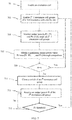
- the monitoring power statuses of the n first resonance coils, and controlling enabling or disabling of the first resonance coils based on the power statuses specifically includes: enabling the n first resonance coils one by one; comparing powers of enabled first resonance coils; and selecting and enabling a first resonance coil with a maximum power that is not equal to "0".
- the powers of the first resonance coils are compared to select the first resonance coil with a maximum power that is not equal to "0", to implement maximum power output to the load and improve charging efficiency.
- the n first resonance coils form 2 n -1 resonance coil groups in a manner of a single coil or a combination of a plurality of first resonance coils.
- the monitoring power statuses of the n first resonance coils, and controlling enabling or disabling of the first resonance coils based on the power statuses specifically further includes: enabling the 2 n -1 resonance coil groups one by one; comparing powers of the resonance coil groups; and selecting a resonance coil group with a maximum power that is not equal to "0".
- a selection range of the resonance coil group with the maximum power is expanded, accuracy of controlling a charging direction is improved, and maximum power output to the load is implemented.
- the wireless charging method further includes: receiving a power of the first resonance coil in an enabled state; and when the first resonance coil in the enabled state is lower than a threshold, indicating that the load moves and the currently enabled first resonance coil is not a first resonance coil that outputs a power, and disabling the previously conducted first resonance coil.
- the power status of the first resonance coil in the enabled state is monitored, to adjust a selection and control solution in time and implement the maximum power output to the load.
- the threshold is designed to be 0.8 times the maximum power.
- the second resonance coil in an enabled state is added, to enhance absorption of the magnetic field energy of the excitation coil; and may resonate with the first resonance coil under excitation of the excitation coil, to enhance magnetic field propagation efficiency.
- excitation coil used in the context of this application is a coil that generates magnetic field energy. Specifically, after receiving a high-frequency alternating current voltage from a voltage conversion circuit, the excitation coil generates the magnetic field energy according to the law of electromagnetic induction.
- a “resonance coil” used in the context of this application is a coil that transmits the magnetic field energy to a load. Specifically, the resonance coil receives a magnetic field generated by the excitation coil, transmits the magnetic field energy to the load, and causes resonance between the excitation coil and the resonance coil through resonance, to increase energy transmission and reduce an energy loss in a transmission process.
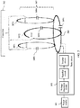
- a launch tower 101 is a wireless charging apparatus and can charge a device such as a mobile phone 103, a notebook computer 105, or a watch 107 that needs to be charged.
- a load is within a radiation range of a magnetic field, the launch tower 101 can wirelessly charge the load regardless of whether the load is in a static state or in a moving state.
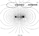
- FIG. 2 is a top view of a transmit coil 201. Two poles in the middle indicate two ends of the transmit coil, coils 1, 2, 3, and 4 are receive coils, and mesh curves indicate a magnetic field generated when power is supplied to the transmit coil 201.
- the transmit coil 201 generates the magnetic field.
- the receive coils 1 and 2 are located within the magnetic field generated by the transmit coil. However, because the magnetic field does not pass through locations of the receive coils 1 and 2, an electric potential difference cannot be formed, causing a charging failure. Although the magnetic field passes through the receive coil 3, an equivalent magnetic field is zero because mutual cancellation occurs when the magnetic field passes through two poles of the coil. Therefore, an electric potential difference cannot be formed, causing a charging failure.
- the receive coil 4 is located within the magnetic field generated by the transmit coil, and the magnetic field passes through the receive coil 4, so that potential energy of the magnetic field can be converted into a current according to the law of electromagnetic induction.
- FIG. 2A is a schematic diagram of an embodiment of this application.
- a resonance coil 213 is further provided in FIG. 2A to play a relay effect.
- a direction of a magnetic field is adjusted, and the magnetic field is enhanced, so that the magnetic field can pass through a receive coil 215.
- three or more resonance coils may be provided in this embodiment of this application, and the excitation coil does not need to be physically connected to the resonance coil.
- the magnetic field is enhanced through resonance between a plurality of resonance coils.
- the magnetic field can be directed to different directions by controlling enabling and disabling of each resonance coil by using an algorithm. Compared with the prior art, this application can not only implement charging in any direction, but also implements relatively simple control and reduces development costs.
- FIG. 3 An embodiment shown in FIG. 3 provides a wireless charging apparatus.
- the apparatus includes a power supply 301, a basic circuit 303, an excitation coil 305, n first resonance coils 307, and a controller 312.
- the basic circuit 303 specifically further includes a voltage regulation circuit, a rectifier circuit, and an inverter circuit.
- the voltage regulation circuit performs voltage step down processing on a 220V/50Hz power grid voltage from the power supply 301, and a voltage step down amplitude is related to an output power and a system design.
- a common terminal device is used as an example. Because the output power is between several watts and several dozens of watts, the power grid voltage may be stepped down to several dozens of volts, for example, 30 volts.
- An actual output power is also related to a current. When a voltage is constant, a magnitude of the current depends on the system design, a design of a receive device, and a distance between a transmit coil and a receive coil.
- the rectifier circuit converts, into a direct current voltage, an alternating current voltage obtained after the voltage step down processing, and the inverter circuit converts the direct current voltage into a high-frequency alternating current voltage to be supplied to the excitation coil 305.
- a frequency of the high-frequency alternating current voltage herein is usually between several dozens of kHz and several MHz, for example, 100 kHz and an ISM frequency band of 6.765 MHz to 6.795 MHz. However, this is not limited to this frequency.
- the excitation coil 305 After receiving the high-frequency alternating current voltage from the basic circuit, the excitation coil 305 generates a magnetic field according to the law of electromagnetic induction.
- the excitation coil 305 is further connected to a resonant capacitor 3091 in series and is configured to generate resonance with a resonance coil in a first resonance coil group 307.
- the n first resonance coils 307 include three first resonance coils 3071, 3072, and 3073.
- the three first resonance coils are located on a path of the magnetic field generated by the excitation coil 305, and are relatively strong in coupling, to implement 360-degree omnidirectional charging.
- the three first resonance coils 3071, 3072, and 3073 are separately located at an edge of the excitation coil, and any one of the three resonance coils has an included angle of 120 degrees to a resonance coil adjacent to the any one of the three resonance coils, so that the magnetic field generated by the excitation coil 305 may be separately transmitted in different directions.
- a direction of each of the three first resonance coils may be arranged at a specific angle to a horizontal plane. The specific angle includes but is not limited to 90 degrees, 60 degrees, 45 degrees, 30 degrees, 15 degrees, or any angle between 0 and 90 degrees. As shown in FIG.
- a magnetic field intensity in different directions may be further enhanced by using an arrangement manner in which directions of three first resonance coils 31092, 31093, and 31094 are arranged at an angle of 45 degrees to the horizontal plane.
- directions of three first resonance coils 32092, 32093, and 32094 are arranged at an angle of 0 degrees to the horizontal plane, and the three first resonance coils 32092, 32093, and 32094 are located on a path of a magnetic field generated by an excitation coil 3305, to implement magnetic field conduction in different directions.
- the three first resonance coils 3071, 3072, and 3073 are further connected to switches 3111, 3112, and 3113 respectively in series.
- the switch is opened or closed by receiving an instruction from the controller 312, to disable or enable the first resonance coil.
- a first resonance coil most corresponding to a location of the charged load may be enabled.
- the first resonance coil most corresponding to the location of the charged load may be a first resonance coil with a maximum power after the first resonance coil is enabled.
- any combination of two or more first resonance coils may be selected and enabled.
- the resonance coil most corresponding to the location may be any combination of first resonance coils with a maximum power after any combination of the first resonance coils is enabled.
- the excitation coil 305 is connected to the resonant capacitor 3091 in series or in parallel.
- the three first resonance coils 3071, 3072, and 3073 are respectively connected to resonant capacitors 3092, 3093, and 3094 in series or in parallel.
- the resonant capacitor can enable a first resonance coil corresponding to the resonant capacitor to operate in a resonant state, thereby increasing a magnetic field transmission power.
- resonance means that resonance occurs between an inductor and a capacitor at a resonance frequency.
- a coil is equivalent to an inductor.
- Four resonant capacitors 3091, 3092, 3093, and 3094 are respectively connected to the excitation coil 305 and the three first resonance coils 3071, 3072, and 3073 in series or in parallel, so that the three first resonance coils resonate at a current frequency of the excitation coil.
- the controller 312 controls enabling or disabling of the first resonance coils by using the switches 3111, 3112, and 3113 based on power statuses of the three first resonance coils 3071, 3072, and 3073.
- the controller 312 may be a processor such as a CPU or a unit machine configured to execute a software instruction, and reads a program to perform a corresponding operation.
- the controller may further be an FPGA chip, and performs a corresponding operation by reading a configuration file in a memory.
- the controller may also be implemented based on an ASIC. Regardless of hardware on which the controller is based, the controller can complete a corresponding control function.
- the control function may be specifically: enabling the three first resonance coils one by one, and obtaining powers P1, P2, and P3 after the three first resonance coils 3071, 3072, and 3073 are enabled; obtaining a maximum power value in P1, P2, and P3 through an internal operation, determining that the maximum power value is not equal to zero, and determining that the first resonance coil is a first resonance coil that needs to be enabled; and sending a switch close instruction to the first resonance coil that needs to be enabled.
- the coil is enabled by using the switch close instruction. For example, through the foregoing operation, it is found that the maximum power that is not equal to zero is P3, and P3 is an output power of the first resonance coil 3073. In this case, the first resonance coil 3073 is enabled.
- the controller 312 may further implement the following control function: detecting periodically or in real time a power of the first resonance coil that has been enabled; comparing the power with a pre-stored threshold; and if the power is less than or equal to the threshold, sending a switch open instruction to the first resonance coil. Specifically, the coil is disabled by using the switch open instruction. If the power is greater than the threshold, the controller 312 does not need to send an instruction for changing an enabled/a disabled state of the resonance coil, and maintains enabling of the first resonance coil.
- the powers P1, P2, and P3 of the three first resonance coils 3071, 3072, and 3073 after being enabled may be obtained in the following manner.
- the excitation coil generates the magnetic field
- the resonance coils conduct the magnetic field
- the magnetic field radiates into air.
- a receive coil After capturing the magnetic field, a receive coil generates an electric potential difference, obtains power data, and transmits the power data to the controller on a transmit side in a wireless communication manner.
- the first resonance coils may form 2 n -1 resonance coil groups in a manner of a single coil or a combination of a plurality of first resonance coils.
- the controller may further perform controlling based on the resonance coil group.
- the controlling may be specifically: enabling the 2 n -1 resonance coil groups one by one, comparing powers of the resonance coil groups, selecting, as a resonance coil group that needs to be enabled, a resonance coil group with a maximum power that is not equal to "0", and sending an enabling instruction to the resonance coil group that needs to be enabled.
- the controlling may be specifically: enabling the 2 n -1 resonance coil groups one by one, comparing powers of the resonance coil groups, selecting, as a resonance coil group that needs to be enabled, a resonance coil group with a maximum power that is not equal to "0", and sending an enabling instruction to the resonance coil group that needs to be enabled.
- the three first resonance coils may form resonance coil groups in a manner of a single coil or a combination of a plurality of first resonance coils, and there may be 23A types, that is, seven combination modes: 3071, 3072, 3073, "3071 and 3072", “3071 and 3073”, “3072 and 3073”, and "3071, 3072, and 3073" respectively.
- the controller 312 obtains powers P1, P2, P3, P4, P5, P6, and P7 after the seven combination modes of resonance coils are enabled, obtains a maximum power value in P1, P2, P3, P5, P6, and P7 through an internal operation, determines that the maximum power value is not equal to zero, and sends an enabling instruction to a combination mode of the first resonance coils with a maximum power. For example, if it is obtained through measurement that an output power P4 of a resonance coil combination "3071 and 3072" is the largest and not equal to zero, the resonance coils 3071 and 3072 are enabled by sending a switch close instruction to the resonance coils "3071 and 3072".
- the controller 312 may further detect periodically or in real time a power of any combination of the first resonance coils that have been conducted; and when the power of the any combination of the first resonance coils is lower than the threshold, send a switch open instruction to the any combination of the first resonance coils, that is, disable the any combination of the first resonance coils.
- the controller 312 obtains the power of the any combination of the first resonance coils that have been enabled; compares the obtained power with the pre-stored threshold; and if the power is less than or equal to the threshold, sends a disabling instruction to the any combination of the first resonance coils, that is, sends an open instruction to a switch of the any combination of the first resonance coils; or if the power is greater than the threshold, does not need to send an instruction for changing an enabled/a disabled state of the any combination of the first resonance coils, and maintains enabling of the any combination of the first resonance coils.
- the any combination of the first resonance coils that have been enabled is the first resonance coils "3071 and 3072".
- a disabling instruction is sent to the first resonance coil 3071 and the first resonance coil 3072, that is, switches of the first resonance coils 3071 and 3072 are opened.
- the apparatus includes a power supply 401, a basic circuit 403, an excitation coil 405, a resonance coil group 407, and a controller 412.
- the power supply 401, the basic circuit 403, the excitation coil 405, and the controller 412 are the same as the power supply 301, the basic circuit 303, and the excitation coil 305 shown in FIG. 3 .
- the resonance coil group 407 includes five first resonance coils 4071, 4072, 4073, 4074, and 4075. This is different from FIG. 3 .
- the five first resonance coils are relatively strongly coupled to the excitation coil 405, to implement 360-degree omnidirectional charging.
- the four first resonance coils 4071, 4072, 4073, and 4074 are separately located at an edge of the excitation coil and are distributed vertically to the excitation coil, and any one of the four first resonance coils is arranged at an included angle of 90 degrees to a first resonance coil adjacent to the any one of the four first resonance coils.
- a magnetic field generated by the excitation coil 405 may be separately transmitted in different directions.
- the first resonance coil 4075 is arranged in parallel with the excitation coil 405, to increase a degree of freedom of the magnetic field in radiating in a vertical direction and project the magnetic field in more directions.
- the first resonance coils 4071, 4072, 4073, 4074, and 4075 are further connected to switches 4111, 4112, 4113, 4114, and 4115 respectively in series.
- the switch is opened or closed by receiving an instruction from the controller 412, to disable or enable the resonance coil.
- a first resonance coil most corresponding to a location of the charged load may be enabled.
- the resonance coil most corresponding to the location of the charged load may be a first resonance coil with a maximum power after the coil is enabled.
- any combination of two or more first resonance coils may be selected and enabled.
- the first resonance coil most corresponding to the location may be any combination of first resonance coils with a maximum power after any combination of the first resonance coils is enabled.
- the first resonance coils 4071, 4072, 4073, 4074, and 4075 are respectively connected to resonant capacitors 4092, 4093, 4094, 4095, and 4096 in series or in parallel, and the excitation coil 405 is connected to a resonant capacitor 4091 in series or in parallel.
- the resonant capacitor can enable a first resonance coil corresponding to the resonant capacitor to operate in a resonant state, thereby increasing a magnetic field transmission power.
- resonance means that resonance occurs between an inductor and a capacitor at a resonance frequency.
- a coil is equivalent to an inductor.
- Six resonant capacitors 4091, 4092, 4093, 4094, 4095, and 4096 are respectively connected to the excitation coil 405 and the five first resonance coils 4071, 4072, 4073, 4074, and 4075 in series or in parallel, so that the five first resonance coils resonate at a current frequency of the excitation coil.
- first resonance coils examples of three first resonance coils and five first resonance coils are shown in the embodiments of FIG. 3 and FIG. 4 , but a quantity of first resonance coils is not limited to three or five provided that the quantity can be more than or equal to three.
- an arrangement angle thereof is correspondingly adjusted, for example, may be an included angle of 90 degrees between any two adjacent first resonance coils.
- the first resonance coils may be arranged in another direction.
- An increase in the quantity of first resonance coils causes more combination modes of the first resonance coils.
- An example of another different quantity of first resonance coils may be obtained by analogy based on the descriptions of the two embodiments that have been provided, and details are not described herein again.
- FIG. 7 shows a simulation result of a magnetic field distribution status on a transmit side in this embodiment. It can be learned that a magnetic field intensity is relatively large after the first resonance coils 4071, 4072, 4073, 4074, and 4075 are separately enabled, and magnetic field distribution in different directions can be implemented by enabling the first resonance coils at different locations, to implement omnidirectional wireless charging.
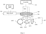
- the apparatus includes a power supply 501, a basic circuit 503, an excitation coil 505, a first resonance coil 507, a second resonance coil 506, and a controller 512.
- the power supply 501, the basic circuit 503, the excitation coil 505, and the controller 512 are the same as the power supply 301, the basic circuit 303, and the excitation coil 305 shown in FIG. 3 .
- the second resonance coil 506 is added. This is different from FIG. 3 .
- the second resonance coil 506 is fully coupled to the excitation coil 505 and is physically connected to three first resonance coils 5072, 5073, and 5074.
- the three first resonance coils are weakly coupled to or uncoupled from the excitation coil, to implement 360-degree omnidirectional charging and enhance a magnetic field propagation power.
- the second resonance coil 506 is close to the excitation coil 505 to implement full coupling, to increase a power of a magnetic field generated by the excitation coil 407 and conduct the magnetic field.
- the first resonance coils 5072, 5073, and 5074 are physically connected to the second resonance coil 506, and an included angle of 120 degrees exists between any two first resonance coils, so that the magnetic field conducted by the second resonance coil 506 can be separately transmitted in different directions.
- the first resonance coils 5072, 5073, and 5074 are further connected to switches 5111, 5112, and 5113 respectively in series.
- the switch is opened or closed by receiving an instruction from the controller 512, to disable or enable the first resonance coil.
- a first resonance coil most corresponding to a location of the charged load may be enabled.
- the first resonance coil most corresponding to the location of the charged load may be a first resonance coil with a maximum power after the coil is enabled.
- any combination of two or more first resonance coils may be selected and enabled.
- the first resonance coil with the maximum power after being enabled may be selected.
- any combination of first resonance coils with a maximum power may be further enabled, to appropriately increase a charging power of the charged load.
- the first resonance coils 5072, 5073, and 5074 are respectively connected to resonant capacitors 5092, 5093, and 5094 in series or in parallel, and the excitation coil 505 is connected to a resonant capacitor 5091 in series or in parallel.
- the resonant capacitor can enable a resonance coil corresponding to the resonant capacitor to operate in a resonant state, thereby increasing a magnetic field transmission power.
- resonance means that resonance occurs between an inductor and a capacitor at a resonance frequency.
- a coil is equivalent to an inductor.
- Four resonant capacitors 4091, 4092, 4093, and 4094 are respectively connected to the excitation coil 505 and the three first resonance coils 5072, 5073, and 5074 in series, so that the three first resonance coils resonate at a current frequency of the excitation coil.
- the second resonance coil 506 is physically connected to the three first resonance coils 5072, 5073, and 5074, and the resonant capacitor can be shared. In another possible case, the second resonance coil 506 may also be connected to a single resonant capacitor in series or in parallel.
- first resonance coils an example of one second resonance coil and three first resonance coils is shown in this embodiment of FIG. 5 , but a quantity of first resonance coils is not limited to three provided that the quantity can be more than or equal to three.
- an arrangement angle thereof is correspondingly adjusted, for example, may be an included angle of 90 degrees between any two adjacent first resonance coils.
- the first resonance coils may be arranged in another direction.
- An example of another different quantity of first resonance coils may be obtained by analogy based on the descriptions of the two embodiments that have been provided, and details are not described herein again.
- FIG. 8A shows a simulation result of a magnetic field distribution status on a transmit side in this embodiment. It can be learned that a magnetic field intensity is relatively large after the first resonance coils 5072, 5073, and 5074 are separately enabled, and magnetic field distribution in different directions can be implemented by enabling the first resonance coils at different locations, to implement omnidirectional wireless charging, further increase a coupling coefficient, increase a transmission power, and further enhance energy of the magnetic field generated by the coil on the transmit side. It is verified through simulation analysis that a magnetic field intensity of a magnetic field at a location of the device is greatly increased by enabling a corresponding coil when it is compared with a case in which a coil is not provided.
- Another embodiment of this application provides a wireless charging method. As shown in FIG. 6 , the method specifically includes the following steps:
- Another embodiment of this application provides a wireless charging method. As shown in FIG. 7 , the method specifically includes the following steps:
- a second resonance coil is added.
- the second resonance coil is in an enabled state, and resonates with the first resonance coil under excitation of the excitation coil, to enhance magnetic field propagation efficiency.
- other method steps are the same as those in the foregoing two method embodiments.
Landscapes
- Engineering & Computer Science (AREA)
- Power Engineering (AREA)
- Computer Networks & Wireless Communication (AREA)
- Charge And Discharge Circuits For Batteries Or The Like (AREA)
Applications Claiming Priority (2)
| Application Number | Priority Date | Filing Date | Title |
|---|---|---|---|
| CN201810672235.3A CN109004768B (zh) | 2018-06-26 | 2018-06-26 | 一种无线充电的装置和方法 |
| PCT/CN2019/081661 WO2020001122A1 (fr) | 2018-06-26 | 2019-04-08 | Dispositif et procédé de charge sans fil |
Publications (2)
| Publication Number | Publication Date |
|---|---|
| EP3780337A1 true EP3780337A1 (fr) | 2021-02-17 |
| EP3780337A4 EP3780337A4 (fr) | 2021-03-10 |
Family
ID=64602037
Family Applications (1)
| Application Number | Title | Priority Date | Filing Date |
|---|---|---|---|
| EP19827113.2A Pending EP3780337A4 (fr) | 2018-06-26 | 2019-04-08 | Dispositif et procédé de charge sans fil |
Country Status (4)
| Country | Link |
|---|---|
| US (1) | US11923690B2 (fr) |
| EP (1) | EP3780337A4 (fr) |
| CN (1) | CN109004768B (fr) |
| WO (1) | WO2020001122A1 (fr) |
Families Citing this family (10)
| Publication number | Priority date | Publication date | Assignee | Title |
|---|---|---|---|---|
| US10416742B2 (en) * | 2017-02-17 | 2019-09-17 | Microsoft Technology Licensing, Llc | Smart battery for ultrafast charging |
| CN109004768B (zh) * | 2018-06-26 | 2022-05-31 | 华为技术有限公司 | 一种无线充电的装置和方法 |
| CN110103739B (zh) * | 2019-04-18 | 2021-03-26 | 南京航空航天大学 | 弱磁场激励三线圈检测装置 |
| WO2020242547A1 (fr) * | 2019-05-30 | 2020-12-03 | University Of Florida Research Foundation | Systèmes et procédés de batterie rechargeable sans fil |
| US11502558B2 (en) * | 2019-11-04 | 2022-11-15 | Nxp Usa, Inc. | Inductive power transfer device |
| CN111030311A (zh) * | 2019-12-25 | 2020-04-17 | 全球能源互联网研究院有限公司 | 一种串行无线能量传输装置 |
| CN113098154B (zh) * | 2020-01-08 | 2024-07-30 | 北京小米移动软件有限公司 | 无线充电方法及装置、电子设备、存储介质 |
| US20220052565A1 (en) * | 2020-08-15 | 2022-02-17 | Aira, Inc. | Resonant Reflection Device Detection |
| CN114204693B (zh) * | 2021-03-17 | 2025-09-30 | 伏达半导体(合肥)股份有限公司 | 无线电能传输系统、无线电能传输装置及方法 |
| CN113815438A (zh) * | 2021-10-27 | 2021-12-21 | 江苏方天电力技术有限公司 | 一种基于电动汽车的无线充电装置 |
Family Cites Families (30)
| Publication number | Priority date | Publication date | Assignee | Title |
|---|---|---|---|---|
| EP1547222B1 (fr) | 2002-06-10 | 2018-10-03 | City University of Hong Kong | Chargeur de batterie inductif plat |
| JP5106237B2 (ja) * | 2008-05-02 | 2012-12-26 | オリンパス株式会社 | 無線給電システム |
| US9601266B2 (en) | 2008-09-27 | 2017-03-21 | Witricity Corporation | Multiple connected resonators with a single electronic circuit |
| US9312924B2 (en) * | 2009-02-10 | 2016-04-12 | Qualcomm Incorporated | Systems and methods relating to multi-dimensional wireless charging |
| US10854378B2 (en) * | 2009-02-23 | 2020-12-01 | Triune Ip Llc | Wireless power transmittal |
| JP5304885B2 (ja) * | 2009-03-17 | 2013-10-02 | 富士通株式会社 | 無線電力供給システム |
| CN102005829B (zh) | 2010-12-03 | 2012-07-25 | 重庆大学 | 用于无线电能传输系统的磁场跟踪伺服机构 |
| KR101859191B1 (ko) * | 2011-03-23 | 2018-05-18 | 삼성전자주식회사 | 무선 전력 전송 시스템, 무선 전력 전송 및 수신 제어 방법 |
| US9006935B2 (en) * | 2011-03-30 | 2015-04-14 | Tdk Corporation | Wireless power feeder/receiver and wireless power transmission system |
| US9099885B2 (en) * | 2011-06-17 | 2015-08-04 | Semiconductor Energy Laboratory Co., Ltd. | Wireless power feeding system |
| US8823217B2 (en) * | 2011-08-31 | 2014-09-02 | Alpha Microelectronics Corp. | One-to-many wireless energy transmission system |
| KR20130028446A (ko) * | 2011-09-09 | 2013-03-19 | 엘지이노텍 주식회사 | 무선 전력 송신 장치 및 그 방법 |
| CN102593964A (zh) | 2012-03-20 | 2012-07-18 | 中国人民解放军国防科学技术大学 | 一种具有方向适应性的磁耦合谐振式无线供电方法及装置 |
| CN103378656B (zh) * | 2012-04-24 | 2015-08-26 | 中惠创智无线供电技术有限公司 | 三维无线电源 |
| GB2526444C (en) * | 2013-02-15 | 2020-09-23 | Murata Manufacturing Co | Wireless power supply apparatus |
| CN104638773A (zh) | 2013-11-14 | 2015-05-20 | 中兴通讯股份有限公司 | 一种无线充电装置及其工作方法 |
| CN104578452B (zh) * | 2014-12-31 | 2017-01-25 | 华南理工大学 | 多维旋转式无线输电装置 |
| US9843217B2 (en) | 2015-01-05 | 2017-12-12 | Witricity Corporation | Wireless energy transfer for wearables |
| CN104617681B (zh) | 2015-01-26 | 2017-07-28 | 南昌大学 | 一种磁耦合谐振式无线电能多向传输三维空心线圈 |
| WO2016119100A1 (fr) | 2015-01-26 | 2016-08-04 | The University Of Hong Kong | Systèmes et procédés de détection de position de charge et de commande de puissance d'un transfert de puissance sans fil omnidirectionnel |
| CN104600877A (zh) * | 2015-02-13 | 2015-05-06 | 哈尔滨工业大学 | 一种具有侧移适应性和旋转适应性的无线电能传输装置 |
| JP2018507678A (ja) * | 2015-03-06 | 2018-03-15 | パワーバイプロキシ リミテッド | 無線電力伝達アダプタ |
| TW201638980A (zh) * | 2015-04-30 | 2016-11-01 | 介面光電股份有限公司 | 薄膜線圈元件及其適用之可撓式無線充電裝置與系統 |
| CN104993614A (zh) * | 2015-07-02 | 2015-10-21 | 中国矿业大学(北京) | 插入中继线圈的不对称的无线输电系统及方法 |
| KR20170022420A (ko) * | 2015-08-20 | 2017-03-02 | (주)창성 | 송신 패드 및 이를 포함하는 무선 충전용 패드 |
| CN105207374B (zh) | 2015-10-30 | 2018-05-11 | 武汉大学 | 无线电能传输系统、方法及跟踪型发射线圈装置 |
| CN206237211U (zh) | 2016-12-19 | 2017-06-09 | 武汉大学 | 一种多维旋转式无线输电装置 |
| CN107276249A (zh) * | 2017-06-12 | 2017-10-20 | 浙江大学 | 一种磁耦合谐振式无线电能传输碗状原边线圈 |
| CN108092417A (zh) | 2017-12-25 | 2018-05-29 | 珠海格力电器股份有限公司 | 一种无线充电装置及其控制方法 |
| CN109004768B (zh) * | 2018-06-26 | 2022-05-31 | 华为技术有限公司 | 一种无线充电的装置和方法 |
-
2018
- 2018-06-26 CN CN201810672235.3A patent/CN109004768B/zh active Active
-
2019
- 2019-04-08 WO PCT/CN2019/081661 patent/WO2020001122A1/fr not_active Ceased
- 2019-04-08 EP EP19827113.2A patent/EP3780337A4/fr active Pending
-
2020
- 2020-11-18 US US16/951,883 patent/US11923690B2/en active Active
Also Published As
| Publication number | Publication date |
|---|---|
| US11923690B2 (en) | 2024-03-05 |
| CN109004768A (zh) | 2018-12-14 |
| WO2020001122A1 (fr) | 2020-01-02 |
| US20210075261A1 (en) | 2021-03-11 |
| CN109004768B (zh) | 2022-05-31 |
| EP3780337A4 (fr) | 2021-03-10 |
Similar Documents
| Publication | Publication Date | Title |
|---|---|---|
| US11923690B2 (en) | Wireless charging apparatus and method | |
| KR102042094B1 (ko) | 교차 연결된 무선 전력 수신기를 배제하기 위한 무선 전력 송신기 및 그 제어 방법 | |
| KR102500565B1 (ko) | 무선 충전에서의 교차 연결 판단 방법 | |
| CN104969442B (zh) | 无线供电装置 | |
| US20150155737A1 (en) | Wireless power orthogonal polarization antenna array | |
| KR20160109955A (ko) | 무선 충전 시스템에서 무선 전력 수신기의 로드 생성 방법 및 무선 전력 수신기 | |
| KR20130045213A (ko) | 무선 전력 송신기 및 그 제어 방법 | |
| WO2012112703A1 (fr) | Systèmes et procédés pour réguler la puissance de sortie d'un transmetteur d'énergie sans fil | |
| US20220393519A1 (en) | Wireless charging device, a receiver device, and an associated method thereof | |
| WO2014011659A1 (fr) | Systèmes, procédés et appareil destinés à des modes de charge sans fil de petits dispositifs | |
| US20180205268A1 (en) | Method for operating wireless power transmission device | |
| CN107069345A (zh) | 一种家用智能插座系统及其控制方法 | |
| KR20170023557A (ko) | 무전전력전송 시스템 및 이의 구동 방법. | |
| US20180166905A1 (en) | Wireless power transmission apparatus and control method therefor, method for controlling wireless power reception apparatus, and wireless power transmission system and wireless power transmission method therefor | |
| KR20150045602A (ko) | 공진방식 기반의 무선충전장치 | |
| CN105006893A (zh) | 一种无线密码键盘的充电系统及充电底座 | |
| KR20170013142A (ko) | 무선 충전 시스템에서의 무선 전력 전송 방법, 무선 전력 송신기, 및 무선 전력 수신기 | |
| KR20170005589A (ko) | 무선 전력 송신 장치 및 무선 전력 송신 시스템 | |
| WO2024243976A1 (fr) | Dispositif de réception d'énergie sans fil utilisant de multiples récepteurs d'énergie sans fil connectés en série pour augmenter la sortie électrique | |
| KR20160070539A (ko) | 무선전력 송신부 | |
| CN113285535B (zh) | 一种用于磁共振无线电能传输异物检测及电能传输的系统 | |
| KR102086859B1 (ko) | 하이브리드형 무선 전력 수신 장치, 하이브리드형 무선 전력 수신 장치에서의 무선 전력 신호 제어 방법, 및 이와 관련된 자기 공명식 무선 전력 수신 장치 | |
| CN217607565U (zh) | 一种无线电传输装置 | |
| CN107872100A (zh) | 一种可移动式无线充电系统及其调相算法优化方法 | |
| Sonawane et al. | Wireless Electricity with Home Automation |
Legal Events
| Date | Code | Title | Description |
|---|---|---|---|
| STAA | Information on the status of an ep patent application or granted ep patent |
Free format text: STATUS: THE INTERNATIONAL PUBLICATION HAS BEEN MADE |
|
| PUAI | Public reference made under article 153(3) epc to a published international application that has entered the european phase |
Free format text: ORIGINAL CODE: 0009012 |
|
| STAA | Information on the status of an ep patent application or granted ep patent |
Free format text: STATUS: REQUEST FOR EXAMINATION WAS MADE |
|
| 17P | Request for examination filed |
Effective date: 20201102 |
|
| AK | Designated contracting states |
Kind code of ref document: A1 Designated state(s): AL AT BE BG CH CY CZ DE DK EE ES FI FR GB GR HR HU IE IS IT LI LT LU LV MC MK MT NL NO PL PT RO RS SE SI SK SM TR |
|
| AX | Request for extension of the european patent |
Extension state: BA ME |
|
| A4 | Supplementary search report drawn up and despatched |
Effective date: 20210208 |
|
| RIC1 | Information provided on ipc code assigned before grant |
Ipc: H02J 50/50 20160101ALI20210202BHEP Ipc: H02J 50/12 20160101ALI20210202BHEP Ipc: H02J 50/40 20160101AFI20210202BHEP Ipc: H02J 50/90 20160101ALI20210202BHEP |
|
| DAV | Request for validation of the european patent (deleted) | ||
| DAX | Request for extension of the european patent (deleted) | ||
| GRAP | Despatch of communication of intention to grant a patent |
Free format text: ORIGINAL CODE: EPIDOSNIGR1 |
|
| STAA | Information on the status of an ep patent application or granted ep patent |
Free format text: STATUS: GRANT OF PATENT IS INTENDED |