EP3780380B1 - Système de moteur électrique et turbocompresseur équipé de ce dernier - Google Patents
Système de moteur électrique et turbocompresseur équipé de ce dernier Download PDFInfo
- Publication number
- EP3780380B1 EP3780380B1 EP19799098.9A EP19799098A EP3780380B1 EP 3780380 B1 EP3780380 B1 EP 3780380B1 EP 19799098 A EP19799098 A EP 19799098A EP 3780380 B1 EP3780380 B1 EP 3780380B1
- Authority
- EP
- European Patent Office
- Prior art keywords
- support
- current
- power source
- armature
- electric motor
- Prior art date
- Legal status (The legal status is an assumption and is not a legal conclusion. Google has not performed a legal analysis and makes no representation as to the accuracy of the status listed.)
- Active
Links
Images


Classifications
-
- H—ELECTRICITY
- H02—GENERATION; CONVERSION OR DISTRIBUTION OF ELECTRIC POWER
- H02K—DYNAMO-ELECTRIC MACHINES
- H02K21/00—Synchronous motors having permanent magnets; Synchronous generators having permanent magnets
- H02K21/02—Details
- H02K21/04—Windings on magnets for additional excitation ; Windings and magnets for additional excitation
- H02K21/046—Windings on magnets for additional excitation ; Windings and magnets for additional excitation with rotating permanent magnets and stationary field winding
-
- H—ELECTRICITY
- H02—GENERATION; CONVERSION OR DISTRIBUTION OF ELECTRIC POWER
- H02K—DYNAMO-ELECTRIC MACHINES
- H02K16/00—Machines with more than one rotor or stator
-
- F—MECHANICAL ENGINEERING; LIGHTING; HEATING; WEAPONS; BLASTING
- F25—REFRIGERATION OR COOLING; COMBINED HEATING AND REFRIGERATION SYSTEMS; HEAT PUMP SYSTEMS; MANUFACTURE OR STORAGE OF ICE; LIQUEFACTION SOLIDIFICATION OF GASES
- F25B—REFRIGERATION MACHINES, PLANTS OR SYSTEMS; COMBINED HEATING AND REFRIGERATION SYSTEMS; HEAT PUMP SYSTEMS
- F25B1/00—Compression machines, plants or systems with non-reversible cycle
- F25B1/04—Compression machines, plants or systems with non-reversible cycle with compressor of rotary type
- F25B1/053—Compression machines, plants or systems with non-reversible cycle with compressor of rotary type of turbine type
-
- H—ELECTRICITY
- H02—GENERATION; CONVERSION OR DISTRIBUTION OF ELECTRIC POWER
- H02K—DYNAMO-ELECTRIC MACHINES
- H02K11/00—Structural association of dynamo-electric machines with electric components or with devices for shielding, monitoring or protection
- H02K11/30—Structural association with control circuits or drive circuits
-
- H—ELECTRICITY
- H02—GENERATION; CONVERSION OR DISTRIBUTION OF ELECTRIC POWER
- H02K—DYNAMO-ELECTRIC MACHINES
- H02K21/00—Synchronous motors having permanent magnets; Synchronous generators having permanent magnets
- H02K21/12—Synchronous motors having permanent magnets; Synchronous generators having permanent magnets with stationary armatures and rotating magnets
- H02K21/14—Synchronous motors having permanent magnets; Synchronous generators having permanent magnets with stationary armatures and rotating magnets with magnets rotating within the armatures
-
- H—ELECTRICITY
- H02—GENERATION; CONVERSION OR DISTRIBUTION OF ELECTRIC POWER
- H02K—DYNAMO-ELECTRIC MACHINES
- H02K7/00—Arrangements for handling mechanical energy structurally associated with dynamo-electric machines, e.g. structural association with mechanical driving motors or auxiliary dynamo-electric machines
- H02K7/08—Structural association with bearings
- H02K7/09—Structural association with bearings with magnetic bearings
-
- H—ELECTRICITY
- H02—GENERATION; CONVERSION OR DISTRIBUTION OF ELECTRIC POWER
- H02K—DYNAMO-ELECTRIC MACHINES
- H02K7/00—Arrangements for handling mechanical energy structurally associated with dynamo-electric machines, e.g. structural association with mechanical driving motors or auxiliary dynamo-electric machines
- H02K7/14—Structural association with mechanical loads, e.g. with hand-held machine tools or fans
-
- H—ELECTRICITY
- H02—GENERATION; CONVERSION OR DISTRIBUTION OF ELECTRIC POWER
- H02K—DYNAMO-ELECTRIC MACHINES
- H02K2205/00—Specific aspects not provided for in the other groups of this subclass relating to casings, enclosures, supports
- H02K2205/03—Machines characterised by thrust bearings
-
- H—ELECTRICITY
- H02—GENERATION; CONVERSION OR DISTRIBUTION OF ELECTRIC POWER
- H02K—DYNAMO-ELECTRIC MACHINES
- H02K5/00—Casings; Enclosures; Supports
- H02K5/04—Casings or enclosures characterised by the shape, form or construction thereof
- H02K5/16—Means for supporting bearings, e.g. insulating supports or means for fitting bearings in the bearing-shields
- H02K5/161—Means for supporting bearings, e.g. insulating supports or means for fitting bearings in the bearing-shields radially supporting the rotary shaft at both ends of the rotor
-
- H—ELECTRICITY
- H02—GENERATION; CONVERSION OR DISTRIBUTION OF ELECTRIC POWER
- H02P—CONTROL OR REGULATION OF ELECTRIC MOTORS, ELECTRIC GENERATORS OR DYNAMO-ELECTRIC CONVERTERS; CONTROLLING TRANSFORMERS, REACTORS OR CHOKE COILS
- H02P25/00—Arrangements or methods for the control of AC motors characterised by the kind of AC motor or by structural details
- H02P25/02—Arrangements or methods for the control of AC motors characterised by the kind of AC motor or by structural details characterised by the kind of motor
Definitions
- a first aspect of the present disclosure is directed to an electric motor system (30).
- the electric motor system (30) includes a drive shaft (31) that rotationally drives a load (21); a bearingless motor (40, 50) that includes a rotor (41, 51) and a stator (44, 54) having an armature winding (46a to 46c, 56a to 56c) and a support winding (47a to 47c, 57a to 57c) and that rotationally drives the drive shaft (31) and supports a radial load of the drive shaft (31) in a contactless manner; a power source unit (61, 62) for applying a voltage to the armature winding (46a to 46c, 56a to 56c) and the support winding (47a to 47c, 57a to 57c); and a control unit (60) that controls the power source unit (61, 62) so that one of an armature voltage VA, which is a voltage across the armature winding (46a to 46c, 56a to
- An eighth aspect of the present disclosure is directed to a turbo compressor (12).
- the turbo compressor (12) includes the electric motor system (30) according to any one of the first to seventh aspects, and an impeller (21) coupled to the drive shaft (31) of the electric motor system (30) and serving as the load (21).
- the components of the electric motor system (30) are provided with various sensors (not illustrated) such as a position sensor, a current sensor, and a rotational speed sensor.
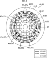
- the first and second bearingless motors (40, 50) are each provided with a position sensor (not illustrated) that outputs a detection signal corresponding to the position of the corresponding rotor (41, 51) in the radial direction
- the thrust magnetic bearing (73) is provided with a position sensor (not illustrated) that outputs a detection signal corresponding to the position of the drive shaft (31) in the thrust direction (axial direction).
- These position sensors are each constituted by, for example, an eddy-current displacement sensor that detects a gap (distance) between the sensor and the object being measured.
- the first and second power source units (61, 62) are each constituted by, for example, a PWM (Pulse Width Modulation) amplifier.
- the first and second power source units (61, 62) constitute a power source unit.
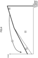
- the high-load torque region (B) is a region that is indicated by symbol B in Fig. 4 and in which the load torque of the impeller (21) and the drive shaft (31) is relatively large and the radial load of the drive shaft (31) is also relatively large.
- the load torque of the impeller (21) and the drive shaft (31) in the turbo compressor (12) becomes maximum at the uppermost-rightmost point of the high-load torque region (B) in Fig. 4 . Note that the radial load of the drive shaft (31) in the turbo compressor (12) does not become maximum in the high-load torque region (B).
- the control unit (60) supplies a voltage to and allows an armature current IA and a support current IS to flow through the armature windings (46a to 46c, 56a to 56c) and the support windings (47a to 47c, 57a to 57c) of the first and second bearingless motors (40, 50) so as to output a radial support force for supporting the radial load in accordance with the state of the turbo compressor (12).
- An electric motor system (30) includes a drive shaft (31) that rotationally drives a load (21); a first and second bearingless motors (40, 50) that include rotors (41, 51) and stators (44, 54) having armature windings (46a to 46c, 56a to 56c) and support windings (47a to 47c, 57a to 57c) and that rotationally drive the drive shaft (31) and support a radial load of the drive shaft (31) in a contactless manner; a first power source unit (61) for applying a voltage to the armature windings (46a to 46c, 56a to 56c); a second power source unit (62) for applying a voltage to the support windings (47a to 47c, 57a to 57c); and a control unit (60) that controls the first and second power source units (61, 62) so that one of an armature voltage VA, which is a voltage across the armature windings (46a to 46c, 56a
- the turbo compressor (12) is disposed in a refrigerant circuit (11) that performs a refrigeration cycle, and is configured to compress refrigerant by using the impeller (21), and when the turbo compressor (12) operates in a rotating-stall generation region (C) or a surging region (D), the control unit (60) controls the first and second power source units (61, 62) so that the armature voltage VA is increased and the support current IS does not exceed a predetermined first upper limit. Accordingly, when the load torque of the first and second bearingless motors (40, 50) is small whereas the required radial support force is large, the radial support force caused by the armature current IA can be increased. Thus, even if the support current IS is kept less than or equal to the first upper limit, the increase in the armature current IA can increase the radial support force of the first and second bearingless motors (40, 50).
- Each of the bearingless motors (40, 50) may be any one of a bearingless motor without saliency in which the d-axis self-inductance and the q-axis self-inductance of the armature are substantially equal, a bearingless motor with inverse saliency in which the d-axis self-inductance of the armature is less than the q-axis self-inductance, and a bearingless motor with forward saliency in which the d-axis self-inductance of the armature is greater than the q-axis self-inductance.
- Examples of the bearingless motor without saliency include a consequent-pole type and a surface permanent magnet type.
- Examples of the bearingless motor with inverse saliency include an interior permanent magnet type, an inset-type, and a BPM type.
- Examples of the bearingless motor with forward saliency include a forward saliency type.
Landscapes
- Engineering & Computer Science (AREA)
- Power Engineering (AREA)
- Physics & Mathematics (AREA)
- Mechanical Engineering (AREA)
- Thermal Sciences (AREA)
- General Engineering & Computer Science (AREA)
- Structures Of Non-Positive Displacement Pumps (AREA)
- Magnetic Bearings And Hydrostatic Bearings (AREA)
- Control Of Positive-Displacement Air Blowers (AREA)
- Control Of Ac Motors In General (AREA)
- Connection Of Motors, Electrical Generators, Mechanical Devices, And The Like (AREA)
Claims (9)
- Système de moteur électrique, comprenantun arbre de transmission (31) entraînant en rotation une charge (21) ;un moteur sans roulement (40, 50) comprenant un rotor (41, 51) et un stator (44, 54) doté d'un enroulement d'induit (46a à 46c, 56a à 56c) et d'un enroulement de support (47a à 47c, 57a à 57c), entraînant en rotation l'arbre de transmission (31) et supportant sans contact une charge radiale de l'arbre de transmission (31) ;un module d'alimentation (61, 62) assurant l'application d'une tension sur l'enroulement d'induit (46a à 46c, 56a à 56c) et sur l'enroulement de support (47a à 47c, 57a à 57c) ; etun module de commande (60) réglant le module d'alimentation (61, 62) afin d'assurer l'émission d'une force de support radiale, à savoir une somme d'une force de support radiale causée par un courant de support IS, qui est un courant qui s'écoule à travers l'enroulement de support (47a à 47c, 57a à 57c), et d'une force de support radiale causée à la fois par le courant de support IS et un courant d'induit IA, à savoir un courant s'écoulant à travers l'enroulement d'induit (46a à 46c, 56a à 56c), et afin d'assurer l'augmentation de l'une d'une tension d'induit VA, qui est une tension dans l'enroulement d'induit (46a à 46c, 56a à 56c), et d'un courant de support IS, qui est un courant qui s'écoule à travers l'enroulement de support (47a à 47c, 57a à 57c), et la diminution de l'autre de la tension d'induit VA et du courant de support IS.
- Système de moteur électrique selon la revendication 1,
le module de commande (60) réglant le module d'alimentation (61, 62) afin d'augmenter la tension d'induit VA et de diminuer le courant de support IS, ou d'augmenter le courant de support IS et de diminuer la tension d'induit VA. - Système de moteur électrique selon la revendication 1 ou 2,
le module de commande (60) réglant le module d'alimentation (61, 62) afin d'augmenter la tension d'induit VA, et de sorte que le courant de support IS ne dépasse pas une première limite supérieure prédéterminée. - Système de moteur électrique selon une quelconque des revendications 1 à 3,
le module de commande (60) réglant le module d'alimentation (61, 62) afin d'augmenter le courant de support IS et de sorte que la tension d'induit VA ne dépasse pas une deuxième limite supérieure prédéterminée. - Système de moteur électrique selon une quelconque des revendications 1 à 4,
le module de commande (60) réglant le module d'alimentation (61, 62) afin de diminuer la tension d'induit VA et d'augmenter le courant de support IS, ou de diminuer le courant de support IS et d'augmenter la tension d'induit VA. - Système de moteur électrique selon une quelconque des revendications 1 à 5,
le module de commande (60) réglant le module d'alimentation (61, 62) afin de diminuer la tension d'induit VA et d'assurer que le courant de support IS dépasse une première limite inférieure prédéterminée. - Système de moteur électrique selon une quelconque des revendications 1 à 6,
le module de commande (60) réglant le module d'alimentation (61, 62) afin de diminuer le courant de support IS, et d'assurer que la tension d'induit VA dépasse une deuxième limite inférieure prédéterminée. - Turbocompresseur comprenant :le système de moteur électrique (30) selon une quelconque des revendications 1 à 7 ; etune roue (21) couplée à l'arbre de transmission (31) du système de moteur électrique (30) et servant de charge (21).
- Turbocompresseur selon la revendication 8,le turbocompresseur (12) étant disposé dans un circuit réfrigérant (11) effectuant un cycle de réfrigération, et configuré pour comprimer le réfrigérant en utilisant la roue (21), etlorsque le turbocompresseur (12) fonctionne dans une zone génératrice à décrochage tournant (C) ou une zone d'amorce de pompage (D), le module de commande (60) réglant le module d'alimentation (61, 62) afin d'augmenter la tension d'induit et afin que le courant de support IS ne dépasse pas une première limite supérieure prédéterminée.
Applications Claiming Priority (3)
| Application Number | Priority Date | Filing Date | Title |
|---|---|---|---|
| JP2018089645 | 2018-05-08 | ||
| JP2018211950A JP6620862B2 (ja) | 2018-05-08 | 2018-11-12 | 電動機システムおよびそれを備えたターボ圧縮機 |
| PCT/JP2019/015161 WO2019216080A1 (fr) | 2018-05-08 | 2019-04-05 | Système de moteur électrique et turbocompresseur équipé de ce dernier |
Publications (3)
| Publication Number | Publication Date |
|---|---|
| EP3780380A1 EP3780380A1 (fr) | 2021-02-17 |
| EP3780380A4 EP3780380A4 (fr) | 2021-04-28 |
| EP3780380B1 true EP3780380B1 (fr) | 2023-08-16 |
Family
ID=68538528
Family Applications (1)
| Application Number | Title | Priority Date | Filing Date |
|---|---|---|---|
| EP19799098.9A Active EP3780380B1 (fr) | 2018-05-08 | 2019-04-05 | Système de moteur électrique et turbocompresseur équipé de ce dernier |
Country Status (3)
| Country | Link |
|---|---|
| US (1) | US11005349B2 (fr) |
| EP (1) | EP3780380B1 (fr) |
| JP (1) | JP6620862B2 (fr) |
Families Citing this family (4)
| Publication number | Priority date | Publication date | Assignee | Title |
|---|---|---|---|---|
| JP7299477B2 (ja) * | 2019-03-27 | 2023-06-28 | ダイキン工業株式会社 | 電動機システム |
| JP7185152B2 (ja) * | 2021-03-19 | 2022-12-07 | ダイキン工業株式会社 | ステータコアの固定構造、遠心式圧縮機、及び固定方法 |
| JP7108218B1 (ja) * | 2021-03-31 | 2022-07-28 | ダイキン工業株式会社 | 電動機、圧縮機、及び冷凍装置 |
| US20250027503A1 (en) * | 2023-07-21 | 2025-01-23 | Trane International Inc. | Compresssor driveshaft magnetic support |
Citations (2)
| Publication number | Priority date | Publication date | Assignee | Title |
|---|---|---|---|---|
| WO2011114912A1 (fr) * | 2010-03-15 | 2011-09-22 | 学校法人東京理科大学 | Moteur sans palier |
| EP3579390A1 (fr) * | 2017-05-09 | 2019-12-11 | Daikin Industries, Ltd. | Turbocompresseur |
Family Cites Families (10)
| Publication number | Priority date | Publication date | Assignee | Title |
|---|---|---|---|---|
| GB2268984B (en) * | 1992-07-23 | 1996-04-03 | Glacier Metal Co Ltd | Magnetic bearing back-up |
| JP2001041238A (ja) * | 1999-07-28 | 2001-02-13 | Seiko Seiki Co Ltd | 複合型電磁石及びラジアル磁気軸受 |
| JP2001258290A (ja) * | 2000-03-08 | 2001-09-21 | Akira Chiba | 磁束検出ベアリングレス回転機の独立制御システム構成法 |
| JP3854998B2 (ja) * | 2003-05-12 | 2006-12-06 | 財団法人理工学振興会 | ベアリングレスモータならびにその回転子位置制御回路および回転子位置制御方法 |
| FR2896285B1 (fr) * | 2006-01-13 | 2008-04-18 | Mecanique Magnetique Sa Soc D | Dispositif de suspension magnetique d'un rotor |
| JP2008295206A (ja) * | 2007-05-24 | 2008-12-04 | Tokyo Univ Of Science | ベアリングレスモータ及びベアリングレスモータ制御システム |
| WO2013015885A1 (fr) * | 2011-06-30 | 2013-01-31 | Carrier Corporation | Détection de pompage de compresseur |
| JP5700033B2 (ja) * | 2012-09-12 | 2015-04-15 | ダイキン工業株式会社 | 磁気軸受 |
| FI127524B (en) * | 2014-06-06 | 2018-08-15 | Lappeenrannan Teknillinen Yliopisto | Control device and method for controlling a magnetic levitation system |
| US20170234364A1 (en) * | 2014-09-01 | 2017-08-17 | Daikin Industries, Ltd. | Magnetic bearing |
-
2018
- 2018-11-12 JP JP2018211950A patent/JP6620862B2/ja active Active
-
2019
- 2019-04-05 EP EP19799098.9A patent/EP3780380B1/fr active Active
-
2020
- 2020-11-04 US US17/089,396 patent/US11005349B2/en active Active
Patent Citations (2)
| Publication number | Priority date | Publication date | Assignee | Title |
|---|---|---|---|---|
| WO2011114912A1 (fr) * | 2010-03-15 | 2011-09-22 | 学校法人東京理科大学 | Moteur sans palier |
| EP3579390A1 (fr) * | 2017-05-09 | 2019-12-11 | Daikin Industries, Ltd. | Turbocompresseur |
Also Published As
| Publication number | Publication date |
|---|---|
| EP3780380A4 (fr) | 2021-04-28 |
| JP2019198209A (ja) | 2019-11-14 |
| EP3780380A1 (fr) | 2021-02-17 |
| US20210050765A1 (en) | 2021-02-18 |
| US11005349B2 (en) | 2021-05-11 |
| JP6620862B2 (ja) | 2019-12-18 |
Similar Documents
| Publication | Publication Date | Title |
|---|---|---|
| US11971045B2 (en) | Turbo compressor | |
| US11005349B2 (en) | Electric motor system, and turbo compressor provided with same | |
| US11300131B2 (en) | Electric motor system and turbo compressor provided therewith | |
| JP6452840B2 (ja) | 回転電機の冷却構造およびその制御方法 | |
| EP3605833B1 (fr) | Système de commande de fonctionnement de charge | |
| KR20000070440A (ko) | 개선된 고속 전기 모터 | |
| CN112088487B (zh) | 电动机系统及包括该电动机系统的涡轮压缩机 | |
| US11949291B2 (en) | Motor having rotor with different core regions, compressor, and air conditioner having the motor | |
| WO2022210900A1 (fr) | Moteur électrique, compresseur et dispositif de réfrigération | |
| JP2021090256A (ja) | 電動機システムおよびそれを備えたターボ圧縮機 | |
| JP7475301B2 (ja) | 電動機システム、ターボ圧縮機、及び冷凍装置 | |
| JP2021184672A (ja) | 電動圧縮機 | |
| Koyanagi et al. | Reduction of Axial Magnetic Force and Starting Current in Single-Sided Axial-Flux Machine with Ring PM Unit and Flux-Weakening Control | |
| JP2020162349A (ja) | 電動機システム | |
| CN120883501A (zh) | 无轴承电机系统、压缩机以及制冷装置 |
Legal Events
| Date | Code | Title | Description |
|---|---|---|---|
| STAA | Information on the status of an ep patent application or granted ep patent |
Free format text: STATUS: THE INTERNATIONAL PUBLICATION HAS BEEN MADE |
|
| PUAI | Public reference made under article 153(3) epc to a published international application that has entered the european phase |
Free format text: ORIGINAL CODE: 0009012 |
|
| STAA | Information on the status of an ep patent application or granted ep patent |
Free format text: STATUS: REQUEST FOR EXAMINATION WAS MADE |
|
| 17P | Request for examination filed |
Effective date: 20201102 |
|
| AK | Designated contracting states |
Kind code of ref document: A1 Designated state(s): AL AT BE BG CH CY CZ DE DK EE ES FI FR GB GR HR HU IE IS IT LI LT LU LV MC MK MT NL NO PL PT RO RS SE SI SK SM TR |
|
| AX | Request for extension of the european patent |
Extension state: BA ME |
|
| A4 | Supplementary search report drawn up and despatched |
Effective date: 20210325 |
|
| RIC1 | Information provided on ipc code assigned before grant |
Ipc: H02P 25/02 20160101AFI20210319BHEP Ipc: H02K 7/09 20060101ALI20210319BHEP Ipc: H02K 7/14 20060101ALI20210319BHEP Ipc: H02K 21/14 20060101ALI20210319BHEP |
|
| DAV | Request for validation of the european patent (deleted) | ||
| DAX | Request for extension of the european patent (deleted) | ||
| STAA | Information on the status of an ep patent application or granted ep patent |
Free format text: STATUS: EXAMINATION IS IN PROGRESS |
|
| 17Q | First examination report despatched |
Effective date: 20220309 |
|
| REG | Reference to a national code |
Ref country code: DE Ref legal event code: R079 Free format text: PREVIOUS MAIN CLASS: H02P0025020000 Ipc: H02K0005160000 Ref country code: DE Ref legal event code: R079 Ref document number: 602019035224 Country of ref document: DE Free format text: PREVIOUS MAIN CLASS: H02P0025020000 Ipc: H02K0005160000 |
|
| GRAP | Despatch of communication of intention to grant a patent |
Free format text: ORIGINAL CODE: EPIDOSNIGR1 |
|
| STAA | Information on the status of an ep patent application or granted ep patent |
Free format text: STATUS: GRANT OF PATENT IS INTENDED |
|
| RIC1 | Information provided on ipc code assigned before grant |
Ipc: H02K 16/00 20060101ALI20221019BHEP Ipc: H02K 5/16 20060101AFI20221019BHEP |
|
| INTG | Intention to grant announced |
Effective date: 20221107 |
|
| RAP3 | Party data changed (applicant data changed or rights of an application transferred) |
Owner name: DAIKIN INDUSTRIES, LTD. |
|
| GRAJ | Information related to disapproval of communication of intention to grant by the applicant or resumption of examination proceedings by the epo deleted |
Free format text: ORIGINAL CODE: EPIDOSDIGR1 |
|
| STAA | Information on the status of an ep patent application or granted ep patent |
Free format text: STATUS: EXAMINATION IS IN PROGRESS |
|
| GRAP | Despatch of communication of intention to grant a patent |
Free format text: ORIGINAL CODE: EPIDOSNIGR1 |
|
| STAA | Information on the status of an ep patent application or granted ep patent |
Free format text: STATUS: GRANT OF PATENT IS INTENDED |
|
| INTC | Intention to grant announced (deleted) | ||
| INTG | Intention to grant announced |
Effective date: 20230327 |
|
| P01 | Opt-out of the competence of the unified patent court (upc) registered |
Effective date: 20230525 |
|
| GRAS | Grant fee paid |
Free format text: ORIGINAL CODE: EPIDOSNIGR3 |
|
| GRAA | (expected) grant |
Free format text: ORIGINAL CODE: 0009210 |
|
| STAA | Information on the status of an ep patent application or granted ep patent |
Free format text: STATUS: THE PATENT HAS BEEN GRANTED |
|
| AK | Designated contracting states |
Kind code of ref document: B1 Designated state(s): AL AT BE BG CH CY CZ DE DK EE ES FI FR GB GR HR HU IE IS IT LI LT LU LV MC MK MT NL NO PL PT RO RS SE SI SK SM TR |
|
| REG | Reference to a national code |
Ref country code: CH Ref legal event code: EP |
|
| REG | Reference to a national code |
Ref country code: DE Ref legal event code: R096 Ref document number: 602019035224 Country of ref document: DE |
|
| REG | Reference to a national code |
Ref country code: IE Ref legal event code: FG4D |
|
| REG | Reference to a national code |
Ref country code: LT Ref legal event code: MG9D |
|
| REG | Reference to a national code |
Ref country code: NL Ref legal event code: MP Effective date: 20230816 |
|
| REG | Reference to a national code |
Ref country code: AT Ref legal event code: MK05 Ref document number: 1601026 Country of ref document: AT Kind code of ref document: T Effective date: 20230816 |
|
| PG25 | Lapsed in a contracting state [announced via postgrant information from national office to epo] |
Ref country code: GR Free format text: LAPSE BECAUSE OF FAILURE TO SUBMIT A TRANSLATION OF THE DESCRIPTION OR TO PAY THE FEE WITHIN THE PRESCRIBED TIME-LIMIT Effective date: 20231117 |
|
| PG25 | Lapsed in a contracting state [announced via postgrant information from national office to epo] |
Ref country code: IS Free format text: LAPSE BECAUSE OF FAILURE TO SUBMIT A TRANSLATION OF THE DESCRIPTION OR TO PAY THE FEE WITHIN THE PRESCRIBED TIME-LIMIT Effective date: 20231216 |
|
| PG25 | Lapsed in a contracting state [announced via postgrant information from national office to epo] |
Ref country code: SE Free format text: LAPSE BECAUSE OF FAILURE TO SUBMIT A TRANSLATION OF THE DESCRIPTION OR TO PAY THE FEE WITHIN THE PRESCRIBED TIME-LIMIT Effective date: 20230816 Ref country code: RS Free format text: LAPSE BECAUSE OF FAILURE TO SUBMIT A TRANSLATION OF THE DESCRIPTION OR TO PAY THE FEE WITHIN THE PRESCRIBED TIME-LIMIT Effective date: 20230816 Ref country code: PT Free format text: LAPSE BECAUSE OF FAILURE TO SUBMIT A TRANSLATION OF THE DESCRIPTION OR TO PAY THE FEE WITHIN THE PRESCRIBED TIME-LIMIT Effective date: 20231218 Ref country code: NO Free format text: LAPSE BECAUSE OF FAILURE TO SUBMIT A TRANSLATION OF THE DESCRIPTION OR TO PAY THE FEE WITHIN THE PRESCRIBED TIME-LIMIT Effective date: 20231116 Ref country code: NL Free format text: LAPSE BECAUSE OF FAILURE TO SUBMIT A TRANSLATION OF THE DESCRIPTION OR TO PAY THE FEE WITHIN THE PRESCRIBED TIME-LIMIT Effective date: 20230816 Ref country code: LV Free format text: LAPSE BECAUSE OF FAILURE TO SUBMIT A TRANSLATION OF THE DESCRIPTION OR TO PAY THE FEE WITHIN THE PRESCRIBED TIME-LIMIT Effective date: 20230816 Ref country code: LT Free format text: LAPSE BECAUSE OF FAILURE TO SUBMIT A TRANSLATION OF THE DESCRIPTION OR TO PAY THE FEE WITHIN THE PRESCRIBED TIME-LIMIT Effective date: 20230816 Ref country code: IS Free format text: LAPSE BECAUSE OF FAILURE TO SUBMIT A TRANSLATION OF THE DESCRIPTION OR TO PAY THE FEE WITHIN THE PRESCRIBED TIME-LIMIT Effective date: 20231216 Ref country code: HR Free format text: LAPSE BECAUSE OF FAILURE TO SUBMIT A TRANSLATION OF THE DESCRIPTION OR TO PAY THE FEE WITHIN THE PRESCRIBED TIME-LIMIT Effective date: 20230816 Ref country code: GR Free format text: LAPSE BECAUSE OF FAILURE TO SUBMIT A TRANSLATION OF THE DESCRIPTION OR TO PAY THE FEE WITHIN THE PRESCRIBED TIME-LIMIT Effective date: 20231117 Ref country code: FI Free format text: LAPSE BECAUSE OF FAILURE TO SUBMIT A TRANSLATION OF THE DESCRIPTION OR TO PAY THE FEE WITHIN THE PRESCRIBED TIME-LIMIT Effective date: 20230816 Ref country code: AT Free format text: LAPSE BECAUSE OF FAILURE TO SUBMIT A TRANSLATION OF THE DESCRIPTION OR TO PAY THE FEE WITHIN THE PRESCRIBED TIME-LIMIT Effective date: 20230816 |
|
| PG25 | Lapsed in a contracting state [announced via postgrant information from national office to epo] |
Ref country code: PL Free format text: LAPSE BECAUSE OF FAILURE TO SUBMIT A TRANSLATION OF THE DESCRIPTION OR TO PAY THE FEE WITHIN THE PRESCRIBED TIME-LIMIT Effective date: 20230816 |
|
| PG25 | Lapsed in a contracting state [announced via postgrant information from national office to epo] |
Ref country code: ES Free format text: LAPSE BECAUSE OF FAILURE TO SUBMIT A TRANSLATION OF THE DESCRIPTION OR TO PAY THE FEE WITHIN THE PRESCRIBED TIME-LIMIT Effective date: 20230816 |
|
| PG25 | Lapsed in a contracting state [announced via postgrant information from national office to epo] |
Ref country code: SM Free format text: LAPSE BECAUSE OF FAILURE TO SUBMIT A TRANSLATION OF THE DESCRIPTION OR TO PAY THE FEE WITHIN THE PRESCRIBED TIME-LIMIT Effective date: 20230816 Ref country code: RO Free format text: LAPSE BECAUSE OF FAILURE TO SUBMIT A TRANSLATION OF THE DESCRIPTION OR TO PAY THE FEE WITHIN THE PRESCRIBED TIME-LIMIT Effective date: 20230816 Ref country code: ES Free format text: LAPSE BECAUSE OF FAILURE TO SUBMIT A TRANSLATION OF THE DESCRIPTION OR TO PAY THE FEE WITHIN THE PRESCRIBED TIME-LIMIT Effective date: 20230816 Ref country code: EE Free format text: LAPSE BECAUSE OF FAILURE TO SUBMIT A TRANSLATION OF THE DESCRIPTION OR TO PAY THE FEE WITHIN THE PRESCRIBED TIME-LIMIT Effective date: 20230816 Ref country code: DK Free format text: LAPSE BECAUSE OF FAILURE TO SUBMIT A TRANSLATION OF THE DESCRIPTION OR TO PAY THE FEE WITHIN THE PRESCRIBED TIME-LIMIT Effective date: 20230816 Ref country code: CZ Free format text: LAPSE BECAUSE OF FAILURE TO SUBMIT A TRANSLATION OF THE DESCRIPTION OR TO PAY THE FEE WITHIN THE PRESCRIBED TIME-LIMIT Effective date: 20230816 Ref country code: SK Free format text: LAPSE BECAUSE OF FAILURE TO SUBMIT A TRANSLATION OF THE DESCRIPTION OR TO PAY THE FEE WITHIN THE PRESCRIBED TIME-LIMIT Effective date: 20230816 |
|
| REG | Reference to a national code |
Ref country code: DE Ref legal event code: R097 Ref document number: 602019035224 Country of ref document: DE |
|
| PLBE | No opposition filed within time limit |
Free format text: ORIGINAL CODE: 0009261 |
|
| STAA | Information on the status of an ep patent application or granted ep patent |
Free format text: STATUS: NO OPPOSITION FILED WITHIN TIME LIMIT |
|
| 26N | No opposition filed |
Effective date: 20240517 |
|
| PG25 | Lapsed in a contracting state [announced via postgrant information from national office to epo] |
Ref country code: SI Free format text: LAPSE BECAUSE OF FAILURE TO SUBMIT A TRANSLATION OF THE DESCRIPTION OR TO PAY THE FEE WITHIN THE PRESCRIBED TIME-LIMIT Effective date: 20230816 |
|
| PG25 | Lapsed in a contracting state [announced via postgrant information from national office to epo] |
Ref country code: BG Free format text: LAPSE BECAUSE OF FAILURE TO SUBMIT A TRANSLATION OF THE DESCRIPTION OR TO PAY THE FEE WITHIN THE PRESCRIBED TIME-LIMIT Effective date: 20230816 |
|
| PG25 | Lapsed in a contracting state [announced via postgrant information from national office to epo] |
Ref country code: MC Free format text: LAPSE BECAUSE OF FAILURE TO SUBMIT A TRANSLATION OF THE DESCRIPTION OR TO PAY THE FEE WITHIN THE PRESCRIBED TIME-LIMIT Effective date: 20230816 |
|
| PG25 | Lapsed in a contracting state [announced via postgrant information from national office to epo] |
Ref country code: MC Free format text: LAPSE BECAUSE OF FAILURE TO SUBMIT A TRANSLATION OF THE DESCRIPTION OR TO PAY THE FEE WITHIN THE PRESCRIBED TIME-LIMIT Effective date: 20230816 Ref country code: BG Free format text: LAPSE BECAUSE OF FAILURE TO SUBMIT A TRANSLATION OF THE DESCRIPTION OR TO PAY THE FEE WITHIN THE PRESCRIBED TIME-LIMIT Effective date: 20230816 |
|
| REG | Reference to a national code |
Ref country code: CH Ref legal event code: PL |
|
| PG25 | Lapsed in a contracting state [announced via postgrant information from national office to epo] |
Ref country code: LU Free format text: LAPSE BECAUSE OF NON-PAYMENT OF DUE FEES Effective date: 20240405 |
|
| REG | Reference to a national code |
Ref country code: BE Ref legal event code: MM Effective date: 20240430 |
|
| PG25 | Lapsed in a contracting state [announced via postgrant information from national office to epo] |
Ref country code: LU Free format text: LAPSE BECAUSE OF NON-PAYMENT OF DUE FEES Effective date: 20240405 |
|
| PG25 | Lapsed in a contracting state [announced via postgrant information from national office to epo] |
Ref country code: BE Free format text: LAPSE BECAUSE OF NON-PAYMENT OF DUE FEES Effective date: 20240430 |
|
| PG25 | Lapsed in a contracting state [announced via postgrant information from national office to epo] |
Ref country code: BE Free format text: LAPSE BECAUSE OF NON-PAYMENT OF DUE FEES Effective date: 20240430 Ref country code: CH Free format text: LAPSE BECAUSE OF NON-PAYMENT OF DUE FEES Effective date: 20240430 |
|
| PG25 | Lapsed in a contracting state [announced via postgrant information from national office to epo] |
Ref country code: IE Free format text: LAPSE BECAUSE OF NON-PAYMENT OF DUE FEES Effective date: 20240405 |
|
| PGFP | Annual fee paid to national office [announced via postgrant information from national office to epo] |
Ref country code: DE Payment date: 20250305 Year of fee payment: 7 |
|
| PG25 | Lapsed in a contracting state [announced via postgrant information from national office to epo] |
Ref country code: CY Free format text: LAPSE BECAUSE OF FAILURE TO SUBMIT A TRANSLATION OF THE DESCRIPTION OR TO PAY THE FEE WITHIN THE PRESCRIBED TIME-LIMIT; INVALID AB INITIO Effective date: 20190405 |
|
| PG25 | Lapsed in a contracting state [announced via postgrant information from national office to epo] |
Ref country code: HU Free format text: LAPSE BECAUSE OF FAILURE TO SUBMIT A TRANSLATION OF THE DESCRIPTION OR TO PAY THE FEE WITHIN THE PRESCRIBED TIME-LIMIT; INVALID AB INITIO Effective date: 20190405 |
|
| PG25 | Lapsed in a contracting state [announced via postgrant information from national office to epo] |
Ref country code: TR Free format text: LAPSE BECAUSE OF FAILURE TO SUBMIT A TRANSLATION OF THE DESCRIPTION OR TO PAY THE FEE WITHIN THE PRESCRIBED TIME-LIMIT Effective date: 20230816 |
|
| PGFP | Annual fee paid to national office [announced via postgrant information from national office to epo] |
Ref country code: GB Payment date: 20260313 Year of fee payment: 8 |
|
| PGFP | Annual fee paid to national office [announced via postgrant information from national office to epo] |
Ref country code: IT Payment date: 20260320 Year of fee payment: 8 |
|
| PGFP | Annual fee paid to national office [announced via postgrant information from national office to epo] |
Ref country code: FR Payment date: 20260309 Year of fee payment: 8 |