EP3780384A1 - Concentrateur solaire - Google Patents
Concentrateur solaire Download PDFInfo
- Publication number
- EP3780384A1 EP3780384A1 EP18915673.0A EP18915673A EP3780384A1 EP 3780384 A1 EP3780384 A1 EP 3780384A1 EP 18915673 A EP18915673 A EP 18915673A EP 3780384 A1 EP3780384 A1 EP 3780384A1
- Authority
- EP
- European Patent Office
- Prior art keywords
- light
- sided
- light receiving
- receiving device
- double
- Prior art date
- Legal status (The legal status is an assumption and is not a legal conclusion. Google has not performed a legal analysis and makes no representation as to the accuracy of the status listed.)
- Withdrawn
Links
- XLYOFNOQVPJJNP-UHFFFAOYSA-N water Substances O XLYOFNOQVPJJNP-UHFFFAOYSA-N 0.000 claims description 6
- 230000003287 optical effect Effects 0.000 claims description 5
- 238000006073 displacement reaction Methods 0.000 claims description 3
- 238000010586 diagram Methods 0.000 description 7
- 238000009434 installation Methods 0.000 description 7
- 238000010248 power generation Methods 0.000 description 5
- 238000006243 chemical reaction Methods 0.000 description 2
- 238000004140 cleaning Methods 0.000 description 2
- 239000000428 dust Substances 0.000 description 2
- 230000006978 adaptation Effects 0.000 description 1
- 230000003044 adaptive effect Effects 0.000 description 1
- 230000009286 beneficial effect Effects 0.000 description 1
- 239000012530 fluid Substances 0.000 description 1
- 230000017525 heat dissipation Effects 0.000 description 1
- 238000012423 maintenance Methods 0.000 description 1
- 239000002184 metal Substances 0.000 description 1
- 238000000034 method Methods 0.000 description 1
- 230000002093 peripheral effect Effects 0.000 description 1
- 239000002096 quantum dot Substances 0.000 description 1
- 239000004065 semiconductor Substances 0.000 description 1
Images


Classifications
-
- H—ELECTRICITY
- H10—SEMICONDUCTOR DEVICES; ELECTRIC SOLID-STATE DEVICES NOT OTHERWISE PROVIDED FOR
- H10F—INORGANIC SEMICONDUCTOR DEVICES SENSITIVE TO INFRARED RADIATION, LIGHT, ELECTROMAGNETIC RADIATION OF SHORTER WAVELENGTH OR CORPUSCULAR RADIATION
- H10F77/00—Constructional details of devices covered by this subclass
- H10F77/40—Optical elements or arrangements
- H10F77/42—Optical elements or arrangements directly associated or integrated with photovoltaic cells, e.g. light-reflecting means or light-concentrating means
- H10F77/488—Reflecting light-concentrating means, e.g. parabolic mirrors or concentrators using total internal reflection
-
- F—MECHANICAL ENGINEERING; LIGHTING; HEATING; WEAPONS; BLASTING
- F24—HEATING; RANGES; VENTILATING
- F24S—SOLAR HEAT COLLECTORS; SOLAR HEAT SYSTEMS
- F24S23/00—Arrangements for concentrating solar-rays for solar heat collectors
- F24S23/70—Arrangements for concentrating solar-rays for solar heat collectors with reflectors
- F24S23/74—Arrangements for concentrating solar-rays for solar heat collectors with reflectors with trough-shaped or cylindro-parabolic reflective surfaces
-
- H—ELECTRICITY
- H02—GENERATION; CONVERSION OR DISTRIBUTION OF ELECTRIC POWER
- H02S—GENERATION OF ELECTRIC POWER BY CONVERSION OF INFRARED RADIATION, VISIBLE LIGHT OR ULTRAVIOLET LIGHT, e.g. USING PHOTOVOLTAIC [PV] MODULES
- H02S40/00—Components or accessories in combination with PV modules, not provided for in groups H02S10/00 - H02S30/00
- H02S40/20—Optical components
- H02S40/22—Light-reflecting or light-concentrating means
-
- Y—GENERAL TAGGING OF NEW TECHNOLOGICAL DEVELOPMENTS; GENERAL TAGGING OF CROSS-SECTIONAL TECHNOLOGIES SPANNING OVER SEVERAL SECTIONS OF THE IPC; TECHNICAL SUBJECTS COVERED BY FORMER USPC CROSS-REFERENCE ART COLLECTIONS [XRACs] AND DIGESTS
- Y02—TECHNOLOGIES OR APPLICATIONS FOR MITIGATION OR ADAPTATION AGAINST CLIMATE CHANGE
- Y02E—REDUCTION OF GREENHOUSE GAS [GHG] EMISSIONS, RELATED TO ENERGY GENERATION, TRANSMISSION OR DISTRIBUTION
- Y02E10/00—Energy generation through renewable energy sources
- Y02E10/40—Solar thermal energy, e.g. solar towers
-
- Y—GENERAL TAGGING OF NEW TECHNOLOGICAL DEVELOPMENTS; GENERAL TAGGING OF CROSS-SECTIONAL TECHNOLOGIES SPANNING OVER SEVERAL SECTIONS OF THE IPC; TECHNICAL SUBJECTS COVERED BY FORMER USPC CROSS-REFERENCE ART COLLECTIONS [XRACs] AND DIGESTS
- Y02—TECHNOLOGIES OR APPLICATIONS FOR MITIGATION OR ADAPTATION AGAINST CLIMATE CHANGE
- Y02E—REDUCTION OF GREENHOUSE GAS [GHG] EMISSIONS, RELATED TO ENERGY GENERATION, TRANSMISSION OR DISTRIBUTION
- Y02E10/00—Energy generation through renewable energy sources
- Y02E10/50—Photovoltaic [PV] energy
- Y02E10/52—PV systems with concentrators
Definitions
- the present disclosure relates to clean energy, in particular to light-concentrating solar apparatus.
- a light-concentrating solar apparatus which includes a light concentrating trough and a double-sided light receiving device.
- the light concentrating trough has two walls extending along a ridge thereof. One side of the two walls is open to form an opening of the light concentrating trough, and the other side is closed or has a gap to form as the ridge.
- the transverse dimension of the opening being greater than the transverse dimension of the ridge, and the inner surfaces of the two walls are reflective surfaces.
- the double-sided light receiving device has a plate shape as a whole, and its front and back surfaces can receive sunlight. It is arranged between the two walls along the ridge of the light concentrating trough, and its front and back sides face the inner surfaces of the two walls respectively.
- the double-sided light receiving device includes a double-sided photosensitive light-energy utilization device, or at least two single-sided photosensitive light-energy utilization devices facing opposite directions.
- the double-sided light receiving device itself can also be a concentrating light-energy utilization device.
- the light concentrating trough and double-sided light receiving device there can be multiple sets of the above-mentioned light concentrating trough and double-sided light receiving device, and they can be arranged overlapping, that is, starting from the second set, the light concentrating trough in each subsequent set is arranged to have its opening facing the ridge of the light concentrating trough in the previous set.
- the outer surfaces of the two walls of the light concentrating trough in a former set are preferably reflective surfaces, and the transverse dimension of the opening of the light concentrating trough in a latter set is preferably larger than the transverse dimension of the opening of the light concentrating trough in the former set.
- the double-sided light receiving device is vertically sandwiched between the light concentrating trough, so that low-cost reflective concentrating can be realized and, due to its adaptation to the deflection of the sun within a certain range, the power generation time of the apparatus can be extended.
- the apparatus can either be fixedly installed lying flat (along the ridge) or fixedly installed upright so as to meet the installation needs of different latitudes.
- multiple sets of light concentrating troughs (and double-sided light receiving devices) can also be arranged in an overlapping manner to double the sunlight collection and conversion capabilities.
- a light-concentrating solar apparatus may include a light concentrating trough 110 and a double-sided light receiving device 120.
- LL shown in the figure and the following figures represents sunlight whose light path is indicated by arrows.
- the light concentrating trough 110 is provided with two walls 111, 111' extending along a ridge RD thereof.
- One side of the two walls is open to form an opening of the light concentrating trough 110, and the other side of the two walls is closed to form the ridge RD.
- the other side opposite to the opening side may not be closed but may have a certain gap for facilitating the drainage of water or dust.
- the gap is the so-called ridge.
- the transverse dimension of the opening of the light concentrating trough is greater than the transverse dimension of the ridge, so as to facilitate the collection and convergence of light.
- the inner surfaces of the two walls i.e. the surfaces of the two walls faced toward each other, are reflective ones.
- the reflective surfaces of the inner surfaces of the light concentrating trough in this embodiment may be flat; however, in other embodiments, they may also be bent or curved so that the inner surfaces of the light concentrating trough is formed into for example a substantially "V" or "U” shape.
- the double-sided light receiving device 120 in a plate-like shape as a whole can receive sunlight at both front and back surfaces thereof.
- the double-sided light receiving device 120 is arranged between the two walls along the ridge RD of the light concentrating trough (for example at the central position between the walls) with the front and back surfaces thereof facing the inner surfaces of the two walls respectively.
- the double-sided light receiving device in this embodiment may be a double-sided photosensitive light-energy utilization device (such as a double-sided photovoltaic panel); however, in other embodiments, it may be two single-sided photosensitive light-energy utilization devices facing opposite directions (such as two single-sided photovoltaic panels arranged back to back).
- the photovoltaic panel herein may generally refer to any device that directly converts light energy into electrical energy, including various semiconductor photovoltaic panels, photovoltaic films, quantum-dot photoelectric conversion devices, etc.
- An end reflective panel 130 which is arranged at an end of the light concentrating trough 110 and has a surface facing the inside of the light concentrating trough as a reflective surface is further included in this embodiment as a preferred embodiment to help improve the collection efficiency of the sunlight without significantly increasing cost.
- the apparatus may adopt installation in a vertical manner along the ridge in the present embodiment, or it may adopt installation in a lying flat or reclining manner along the ridge in other embodiments.
- the above-mentioned light concentrating trough and the double-sided light receiving device can be combined and arranged with multiple sets thereof in an overlapping manner, in which the opening of a light concentrating trough in each subsequent set is arranged to face the ridge of a light concentrating trough in a previous set.
- the sets of the combination can be arranged in a front-and-rear overlapped manner in the case of vertical installation, or the sets of the combination can be arranged in an up-and-down overlapped manner in the case of lying-flat installation.
- the double-sided light receiving device only includes photovoltaic panels in this embodiment, but it can also include other types of light-energy utilization device such as a photothermal utilization device, or a combination of a photovoltaic panel and a photothermal utilization device.
- the double-sided light receiving device may also be a combination of a light-energy utilization device and a light guiding device, which can be called a double-sided "concentrating light-energy utilization device".
- the light guiding device can be selected from, for example, a conical tube and a bar-type groove, in which the conical tube has a reflective surface as its inner surface and a top opening larger than the one at the bottom, and a corresponding light-energy utilization device is arranged at the bottom of the conical tube.
- the bar-type groove provided with reflective surfaces as walls on both sides has a width at the top greater than that at the bottom, and a corresponding light-energy utilization device is arranged at the bottom of the light concentrating trough.
- These light guiding devices formed by the reflective surfaces can increase the concentration ratio of the apparatus at a lower cost.
- the concentrating light-energy utilization device may include a plurality of units which are closely arranged to form a row structure, a column structure or an array structure.
- Each unit includes a light-energy utilization device and a conical tube or a light concentrating trough.
- Such structure miniaturizes a single unit, which is beneficial to maintain the optical parameters (e.g. the angle of the reflective surface of the light guiding device) and reduce the height of the light receiving device.
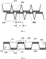
- FIG. 2 a longitudinal section of a preferred double-sided concentrating light-energy utilization device is schematically shown.
- the shown device adopts a structure in which a plurality of units are integrated, including multiple front units A10 with openings on the front side and multiple back units A10' with openings on the back side.
- Each unit includes a bar-type groove and a photovoltaic panel arranged at the bottom of the groove.
- the walls A11, A11' and A12, A12' of the bar-type groove are reflective surfaces.
- the multiple front units A10 are arranged in one layer, and the multiple back units A10' are arranged in another layer. The arrangement of the two layers is identical and mirror-symmetrical.
- each pair of symmetrically arranged front and back units can use the same double-sided photosensitive device A20.
- each pair of symmetrically arranged front and back units may also use single-sided photosensitive devices arranged back to back.
- the entire device can be packaged with a transparent cover A30 to facilitate cleaning.
- FIG. 3 a longitudinal section of another preferred double-sided concentrating light-energy utilization device is schematically shown.
- the structure of the shown device is similar to that of the device shown in FIG. 2 , comprising multiple front units B10 and multiple back units B10'.
- the difference from FIG. 2 is that there is a predefined displacement distance d on the whole between the layer formed by the front unit B10 and the layer formed by the back unit B10' in general.
- the front unit and back unit each employ a single-sided photosensitive device B20 or B20'.
- the displacement distance on the whole between the layers may preferably be half of the width w of the photosensitive device.
- FIG. 4 a longitudinal section of still another preferred double-sided concentrating light-energy utilization device is schematically shown.
- the device includes a plurality of front units C10 and a plurality of back units C10'.
- the units C10 and the units C10' are alternately arranged on the same layer, forming a wave-shaped groove structure. Therefore, C10 and C10' share the wall C11, and both surfaces of the wall C11 are reflective surfaces.
- the photosensitive devices C20, C20' respectively arranged at the bottoms of C10, C10' can be single-sided photosensitive devices, but preferably double-sided photosensitive devices are used to fully utilize solar energy.
- the entire device of FIG. 4 can be packaged with an ambient cover in a preferred structure, including a transparent top cover C30, a transparent bottom cover C30', and side covers (not shown).
- a working fluid can be provided for heat dissipation or thermal energy utilization.
- Pipes C41, C42 connected to an external system can be provided on the end cover to facilitate heat exchange.
- the light-concentrating solar apparatus can employ an ambient cover to form a closed cavity as a whole, and each reflective surface and each light receiving device are arranged in the cavity to facilitate cleaning of dust and protect internal devices. At least a part of the peripheral ambient covers is transparent, and these transparent ambient covers are arranged on the light path where sunlight enters the light-energy utilization device.
- a light-concentrating solar apparatus may include two sets of light concentrating troughs and double-sided light receiving devices.
- the inner and outer surfaces of the two walls 211, 211' of the light concentrating trough 210 in the first set are both reflective ones formed as folded surfaces.
- the reflective surface of the outer surface helps to condense light for the subsequent light concentrating trough.
- the inner surfaces of the two walls 241, 241' of the light concentrating trough 240 in the second set are reflective ones formed as flat surfaces.
- the outer surface need not be a reflective one.
- the light concentrating trough 240 is arranged to make its opening facing the ridge of the light concentrating trough 210 in the previous set, and the transverse dimension of the opening of the light concentrating trough 240 is larger than the transverse dimension of the opening of the light concentrating trough 210.
- the double-sided light receiving device 220 in the first set and the double-sided light receiving device 250 in the second set are respectively erected at the center of the light concentrating troughs 210, 240.
- double-sided photovoltaic panels or double-sided concentrating light-energy utilization device as described above can be used.
- more sets of light concentrating troughs and double-sided light receiving devices can be adopted to collect and convert more solar energy.
- a light-concentrating solar apparatus may include light concentrating trough 310 and double-sided light receiving device 320 which are similar to the light concentrating trough 210 and the double-sided light receiving device 220 and will not be repeated here.
- a single-sided light receiving device 360 and inclined reflective panels 371, 371' arranged on both side of the single-sided light receiving device are further included in this embodiment. These reflective panels can help to condense the sunlight outside the concentrating trough onto the single-sided light receiving device 360.
- the single-sided light receiving device 360 shaped as plate-like overall has a light receiving surface facing the ridge of the light concentrating trough 310 and arranged outside the light concentrating trough 310.
- the single-sided light receiving device 360 may include a single-sided photosensitive light-energy utilization device, such as a single-sided photovoltaic panel, or may also be a combination of a single-sided photosensitive light-energy utilization device and a light guiding device, such as one layer of the double-sided concentrating light-energy utilization device shown in FIG. 2 or FIG. 3 .
- the apparatus of this embodiment can also be regarded as two overlapping light concentrating troughs, in which the light receiving device arranged in the last light concentrating trough is lying flat instead of upright, and is a single-sided light receiving device.
- the single-sided light receiving device 360 is needed to be replaced with a double-sided light receiving device and the back surfaces of the reflective panels 371, 371' are also configured as reflective ones.
- a water heater 380 is further included in this embodiment as a preferred embodiment.
- the water heater 380 is also arranged under the back side of the light receiving surface of the single-sided light receiving device 360, and is thermally connected with the single-sided light receiving device 360 and the double-sided light receiving device 320. Its function is to cool the single-sided light receiving device 360 and the double-sided light receiving device 320, and to provide hot water at the same time.
- a metal plate (not shown) can be provided inside the double-sided light receiving device, which can be inserted into the water heater 380 to achieve rapid heat conduction.
- a light-concentrating solar apparatus may include two sets of light concentrating troughs and double-sided light receiving devices, i.e. light concentrating troughs 410, 440 and double-sided light receiving devices 420, 450.
- light concentrating troughs 410, 440 and double-sided light receiving devices 420, 450 There are similarities between they and the light concentrating troughs 210, 240 and the double-sided light receiving device 220, 250 (which will not be repeated here), and the difference therebetween is that the outer surfaces of the two walls 441, 441' of the light concentrating trough 440 are also reflective surfaces.
- a single-sided light receiving device 460 and reflective panels 471, 471' arranged on both sides thereof are also included in this embodiment. They are similar to the single-sided light receiving device 360 and the reflective panels 371, 371' in the Embodiment 3, except that the reflective panels 471, 471' are lying flat due to the requirement of a larger opening.
- a Fresnel lens 480 arranged on the optical path of the sunlight before it is incident on the reflective surface of the light concentrating trough 410 is further included in this embodiment as a preferred embodiment.
- the Fresnel lens 480 selected from a linear Fresnel lens and a partial Fresnel lens can be used to deflect the sunlight downward to help to increase the concentration ratio of the light concentrating trough 410.
- the so-called "linear Fresnel lens” means that the focal center of the lens is not a point but a line.
- partial Fresnel lens means that the tooth surface of the Fresnel lens is not a complete symmetrical pattern but only a part of it; for example, a partial Fresnel lens is formed by cutting a complete circular Fresnel lens at a position close to the diameter thereof.
- An end reflective panel 430 to improve the overall performance of the apparatus is also included in this embodiment as a preferred embodiment.
- a large amount of power generation in a unit space can be achieved, making it possible to extend the daily power generation time with a high light energy utilization efficiency thereof.
- the apparatus of this embodiment can also be regarded as three overlapped light concentrating troughs, in which the last arranged light concentrating trough has been opened as a plate-like shape, and the light receiving device thereof is a flat single-sided light receiving device.
Landscapes
- Engineering & Computer Science (AREA)
- Physics & Mathematics (AREA)
- Life Sciences & Earth Sciences (AREA)
- Sustainable Development (AREA)
- Sustainable Energy (AREA)
- Thermal Sciences (AREA)
- Chemical & Material Sciences (AREA)
- Combustion & Propulsion (AREA)
- Mechanical Engineering (AREA)
- General Engineering & Computer Science (AREA)
- Photovoltaic Devices (AREA)
- Heat-Pump Type And Storage Water Heaters (AREA)
Applications Claiming Priority (1)
| Application Number | Priority Date | Filing Date | Title |
|---|---|---|---|
| PCT/CN2018/083166 WO2019200503A1 (fr) | 2018-04-16 | 2018-04-16 | Concentrateur solaire |
Publications (2)
| Publication Number | Publication Date |
|---|---|
| EP3780384A1 true EP3780384A1 (fr) | 2021-02-17 |
| EP3780384A4 EP3780384A4 (fr) | 2021-11-10 |
Family
ID=68240484
Family Applications (1)
| Application Number | Title | Priority Date | Filing Date |
|---|---|---|---|
| EP18915673.0A Withdrawn EP3780384A4 (fr) | 2018-04-16 | 2018-04-16 | Concentrateur solaire |
Country Status (5)
| Country | Link |
|---|---|
| US (1) | US20210036654A1 (fr) |
| EP (1) | EP3780384A4 (fr) |
| JP (1) | JP2021519054A (fr) |
| CN (1) | CN111869099A (fr) |
| WO (1) | WO2019200503A1 (fr) |
Families Citing this family (2)
| Publication number | Priority date | Publication date | Assignee | Title |
|---|---|---|---|---|
| WO2022094777A1 (fr) * | 2020-11-04 | 2022-05-12 | 博立多媒体控股有限公司 | Dispositif d'utilisation d'énergie solaire |
| JP2025510780A (ja) * | 2022-04-07 | 2025-04-15 | ボリーメディアコミュニケーションズ(シンチェン)カンパニーリミテッド | 太陽エネルギー利用ユニット |
Family Cites Families (23)
| Publication number | Priority date | Publication date | Assignee | Title |
|---|---|---|---|---|
| JPS60149848A (ja) * | 1984-01-17 | 1985-08-07 | Kobe Steel Ltd | ソ−ラコレクタ用熱交換器 |
| AU707630B2 (en) * | 1994-10-05 | 1999-07-15 | Hisao Izumi | Hybrid solar collector for generating electricity and heat by separating solar rays into long wavelength and short wavelength |
| US5538563A (en) * | 1995-02-03 | 1996-07-23 | Finkl; Anthony W. | Solar energy concentrator apparatus for bifacial photovoltaic cells |
| US6971756B2 (en) * | 2000-12-18 | 2005-12-06 | Svv Technology Innovations, Inc. | Apparatus for collecting and converting radiant energy |
| US20090308432A1 (en) * | 2008-06-13 | 2009-12-17 | General Electric Company | Reflective light concentrator |
| ITTO20080706A1 (it) * | 2008-09-26 | 2010-03-27 | Ocap S P A | Riflettore solare con struttura di supporto in lamiera metallica cellulare e procedimento per la sua fabbricazione |
| KR100922710B1 (ko) * | 2009-02-25 | 2009-10-21 | 솔라비토(주) | 태양광 발전장치 및 그 제어방법 |
| CN101872796A (zh) * | 2009-04-24 | 2010-10-27 | 云南师范大学 | 一种高效低聚光光伏组件 |
| CN101995105A (zh) * | 2009-08-26 | 2011-03-30 | 赵风雏 | 聚光槽 |
| US8304644B2 (en) * | 2009-11-20 | 2012-11-06 | Sunpower Corporation | Device and method for solar power generation |
| TWI435455B (zh) * | 2011-06-23 | 2014-04-21 | Univ Nat Pingtung Sci & Tech | 多層級太陽能裝置 |
| CN103022206B (zh) * | 2012-12-18 | 2015-03-04 | 内蒙古建筑职业技术学院 | 一种槽式复合抛物面聚光发电组件 |
| NL1040088C2 (en) * | 2013-03-11 | 2014-09-15 | Linesolar Ip B V | Concentrating solar panel with diffuse light conversion. |
| CN103836811B (zh) * | 2013-12-10 | 2016-01-27 | 杭州奕华能源科技有限公司 | 双面反射集光装置 |
| KR102274301B1 (ko) * | 2014-03-14 | 2021-07-07 | 주성엔지니어링(주) | 태양광 발전장치 및 이를 이용한 태양광 발전 방법 |
| CN103968564B (zh) * | 2014-04-28 | 2016-02-03 | 江苏恒星聚能能源科技有限公司 | 一种平板聚光型太阳能无水箱热水器 |
| CN104300893A (zh) * | 2014-08-18 | 2015-01-21 | 杭州慈源科技有限公司 | 多边结构双面发电太阳能电池组件 |
| TW201610378A (zh) * | 2014-09-05 | 2016-03-16 | ming-xiu Li | 增效式太陽能熱水器 |
| RU2583317C1 (ru) * | 2015-01-29 | 2016-05-10 | Общество с ограниченной ответственностью "СОЛЭКС-Р" | Комбинированная концентраторная фотоэлектрическая установка |
| CN205508836U (zh) * | 2016-04-08 | 2016-08-24 | 合肥中南光电有限公司 | 一种双面聚光光伏模块 |
| CN206575375U (zh) * | 2017-02-09 | 2017-10-20 | 李康斌 | 双面发电光伏组件 |
| CN206802997U (zh) * | 2017-06-17 | 2017-12-26 | 乌鲁木齐中亚环地卫星科技服务有限公司 | 一种节能环保的太阳能路灯的阳光聚集反射器 |
| CN107332505A (zh) * | 2017-07-20 | 2017-11-07 | 长春工程学院 | 一种聚光式晶格发电光伏板装置 |
-
2018
- 2018-04-16 WO PCT/CN2018/083166 patent/WO2019200503A1/fr not_active Ceased
- 2018-04-16 EP EP18915673.0A patent/EP3780384A4/fr not_active Withdrawn
- 2018-04-16 JP JP2020554855A patent/JP2021519054A/ja active Pending
- 2018-04-16 US US17/043,824 patent/US20210036654A1/en not_active Abandoned
- 2018-04-16 CN CN201880091337.4A patent/CN111869099A/zh active Pending
Also Published As
| Publication number | Publication date |
|---|---|
| WO2019200503A1 (fr) | 2019-10-24 |
| JP2021519054A (ja) | 2021-08-05 |
| EP3780384A4 (fr) | 2021-11-10 |
| US20210036654A1 (en) | 2021-02-04 |
| CN111869099A (zh) | 2020-10-30 |
Similar Documents
| Publication | Publication Date | Title |
|---|---|---|
| WO1990004142A1 (fr) | Unite de conversion solaire/electrique et systeme | |
| KR101955774B1 (ko) | 집광이 가능한 태양광 발전과 태양광의 집열 구조를 갖는 태양열 집열장치 | |
| EP3703253A1 (fr) | Système d'énergie solaire à concentration de lumière | |
| US20140041708A1 (en) | Low-cost thin-film concentrator solar cells | |
| KR20100073084A (ko) | 태양광열 이용장치 및 그 조립방법 | |
| CN105356846B (zh) | 一种光伏光热一体化组件 | |
| AU2018422303B2 (en) | Double-sided light-concentrating solar apparatus and system | |
| JP7636562B2 (ja) | 太陽エネルギー利用装置 | |
| EP3767824A1 (fr) | Dispositif solaire à concentration de lumière de surface latérale | |
| KR20070104300A (ko) | 태양전지 집속모듈 구조 | |
| EP3780384A1 (fr) | Concentrateur solaire | |
| US4056090A (en) | Solar heat collector | |
| JP2023551258A (ja) | 太陽エネルギー利用装置 | |
| EP4503144A1 (fr) | Unité d'utilisation d'énergie solaire | |
| US20110088751A1 (en) | Non-imaging radiant energy concentrator | |
| KR20180103242A (ko) | 태양열 흡수효율증가용 표면코팅을 갖는 pv모듈 및 이를 포함하는 태양광/열 집열모듈 구조 | |
| KR102825015B1 (ko) | 태양열 태양광 융합 발전장치 | |
| CN217817513U (zh) | 一种太阳能光热利用的双凸透镜阵列 | |
| WO2022178826A1 (fr) | Dispositif d'utilisation d'énergie solaire | |
| KR101610071B1 (ko) | 태양광-열 모듈 구조 | |
| WO2014160856A1 (fr) | Boîtier de module pour photovoltaïque concentré à canaux de refroidissement intégrés | |
| WO2012165899A2 (fr) | Module de cellule solaire à forte concentration lumineuse | |
| UA44600A (uk) | Сонячний фокусуючий теплофотоелектричний колектор |
Legal Events
| Date | Code | Title | Description |
|---|---|---|---|
| STAA | Information on the status of an ep patent application or granted ep patent |
Free format text: STATUS: THE INTERNATIONAL PUBLICATION HAS BEEN MADE |
|
| PUAI | Public reference made under article 153(3) epc to a published international application that has entered the european phase |
Free format text: ORIGINAL CODE: 0009012 |
|
| STAA | Information on the status of an ep patent application or granted ep patent |
Free format text: STATUS: REQUEST FOR EXAMINATION WAS MADE |
|
| 17P | Request for examination filed |
Effective date: 20201112 |
|
| AK | Designated contracting states |
Kind code of ref document: A1 Designated state(s): AL AT BE BG CH CY CZ DE DK EE ES FI FR GB GR HR HU IE IS IT LI LT LU LV MC MK MT NL NO PL PT RO RS SE SI SK SM TR |
|
| AX | Request for extension of the european patent |
Extension state: BA ME |
|
| DAV | Request for validation of the european patent (deleted) | ||
| DAX | Request for extension of the european patent (deleted) | ||
| A4 | Supplementary search report drawn up and despatched |
Effective date: 20211008 |
|
| RIC1 | Information provided on ipc code assigned before grant |
Ipc: H01L 31/054 20140101ALI20211004BHEP Ipc: H02S 40/22 20140101AFI20211004BHEP |
|
| STAA | Information on the status of an ep patent application or granted ep patent |
Free format text: STATUS: THE APPLICATION HAS BEEN WITHDRAWN |
|
| 18W | Application withdrawn |
Effective date: 20220118 |