EP3780507B1 - Verfahren und system zur durchführung doppelter nachrichtenarbitrierung - Google Patents
Verfahren und system zur durchführung doppelter nachrichtenarbitrierung Download PDFInfo
- Publication number
- EP3780507B1 EP3780507B1 EP19191153.6A EP19191153A EP3780507B1 EP 3780507 B1 EP3780507 B1 EP 3780507B1 EP 19191153 A EP19191153 A EP 19191153A EP 3780507 B1 EP3780507 B1 EP 3780507B1
- Authority
- EP
- European Patent Office
- Prior art keywords
- network
- message
- arbitration
- dcan
- communication network
- Prior art date
- Legal status (The legal status is an assumption and is not a legal conclusion. Google has not performed a legal analysis and makes no representation as to the accuracy of the status listed.)
- Active
Links
Images



Classifications
-
- H—ELECTRICITY
- H04—ELECTRIC COMMUNICATION TECHNIQUE
- H04L—TRANSMISSION OF DIGITAL INFORMATION, e.g. TELEGRAPHIC COMMUNICATION
- H04L67/00—Network arrangements or protocols for supporting network services or applications
- H04L67/01—Protocols
- H04L67/10—Protocols in which an application is distributed across nodes in the network
-
- H—ELECTRICITY
- H04—ELECTRIC COMMUNICATION TECHNIQUE
- H04L—TRANSMISSION OF DIGITAL INFORMATION, e.g. TELEGRAPHIC COMMUNICATION
- H04L12/00—Data switching networks
- H04L12/28—Data switching networks characterised by path configuration, e.g. LAN [Local Area Networks] or WAN [Wide Area Networks]
- H04L12/40—Bus networks
-
- H—ELECTRICITY
- H04—ELECTRIC COMMUNICATION TECHNIQUE
- H04L—TRANSMISSION OF DIGITAL INFORMATION, e.g. TELEGRAPHIC COMMUNICATION
- H04L1/00—Arrangements for detecting or preventing errors in the information received
- H04L1/004—Arrangements for detecting or preventing errors in the information received by using forward error control
- H04L1/0056—Systems characterized by the type of code used
-
- H—ELECTRICITY
- H04—ELECTRIC COMMUNICATION TECHNIQUE
- H04L—TRANSMISSION OF DIGITAL INFORMATION, e.g. TELEGRAPHIC COMMUNICATION
- H04L12/00—Data switching networks
- H04L12/28—Data switching networks characterised by path configuration, e.g. LAN [Local Area Networks] or WAN [Wide Area Networks]
- H04L12/40—Bus networks
- H04L12/40006—Architecture of a communication node
-
- H—ELECTRICITY
- H04—ELECTRIC COMMUNICATION TECHNIQUE
- H04L—TRANSMISSION OF DIGITAL INFORMATION, e.g. TELEGRAPHIC COMMUNICATION
- H04L12/00—Data switching networks
- H04L12/28—Data switching networks characterised by path configuration, e.g. LAN [Local Area Networks] or WAN [Wide Area Networks]
- H04L12/40—Bus networks
- H04L12/40006—Architecture of a communication node
- H04L12/40032—Details regarding a bus interface enhancer
-
- H—ELECTRICITY
- H04—ELECTRIC COMMUNICATION TECHNIQUE
- H04L—TRANSMISSION OF DIGITAL INFORMATION, e.g. TELEGRAPHIC COMMUNICATION
- H04L12/00—Data switching networks
- H04L12/28—Data switching networks characterised by path configuration, e.g. LAN [Local Area Networks] or WAN [Wide Area Networks]
- H04L12/40—Bus networks
- H04L12/40052—High-speed IEEE 1394 serial bus
- H04L12/40084—Bus arbitration
-
- H—ELECTRICITY
- H04—ELECTRIC COMMUNICATION TECHNIQUE
- H04L—TRANSMISSION OF DIGITAL INFORMATION, e.g. TELEGRAPHIC COMMUNICATION
- H04L12/00—Data switching networks
- H04L12/28—Data switching networks characterised by path configuration, e.g. LAN [Local Area Networks] or WAN [Wide Area Networks]
- H04L12/40—Bus networks
- H04L12/40143—Bus networks involving priority mechanisms
-
- H—ELECTRICITY
- H04—ELECTRIC COMMUNICATION TECHNIQUE
- H04L—TRANSMISSION OF DIGITAL INFORMATION, e.g. TELEGRAPHIC COMMUNICATION
- H04L43/00—Arrangements for monitoring or testing data switching networks
- H04L43/10—Active monitoring, e.g. heartbeat, ping or trace-route
-
- H—ELECTRICITY
- H04—ELECTRIC COMMUNICATION TECHNIQUE
- H04L—TRANSMISSION OF DIGITAL INFORMATION, e.g. TELEGRAPHIC COMMUNICATION
- H04L69/00—Network arrangements, protocols or services independent of the application payload and not provided for in the other groups of this subclass
- H04L69/18—Multiprotocol handlers, e.g. single devices capable of handling multiple protocols
-
- H—ELECTRICITY
- H04—ELECTRIC COMMUNICATION TECHNIQUE
- H04L—TRANSMISSION OF DIGITAL INFORMATION, e.g. TELEGRAPHIC COMMUNICATION
- H04L12/00—Data switching networks
- H04L12/28—Data switching networks characterised by path configuration, e.g. LAN [Local Area Networks] or WAN [Wide Area Networks]
- H04L12/40—Bus networks
- H04L2012/40208—Bus networks characterized by the use of a particular bus standard
- H04L2012/40215—Controller Area Network CAN
Definitions
- the present invention relates to a method and system for performing message arbitration, especially double message arbitration, in a first communication network, based on arbitration information of a physically existing second communication network.
- vehicles, airplanes and the like employ many sensors, actuators, controllers, sub-systems, buses, etc. that require appropriate controlling of the communication between interconnected nodes or devices.
- sensors, actuators, controllers, sub-systems, buses, etc. that require appropriate controlling of the communication between interconnected nodes or devices.
- modern cars comprise a plurality of electronic control devices for various subsystems.
- the biggest processor is the engine control unit.
- Others are used for transmission, airbags, audio systems, power windows, doors, mirror adjustment etc.
- Some of these form independent subsystems or communication channel, but inter-communications among other systems may be essential for the security, reliability and/or convenience of a modern car.
- various communication protocols were introduced; some of which employ arbitration to allow random access of control devices to the network.
- CAN standard is an example to one possible bus system, but other communication protocols can also be used in parallel.
- the systems comprise a plurality of devices interconnected to communicate over different protocols there is a need in ensuring a proper arbitration of the message flow within the network.
- EP 1 921 801 A2 discloses generally a network with a plurality of nodes and a plurality of bidirectional point to point connection links. To ensure a proper message communication a priority-based arbitration technique is implemented. EP 1 921 801 A2 discloses the well-known priority based arbitration of the CAN-protocol.
- US 2004/254700 A1 discloses a vehicle communication network with a plurality of network elements and a plurality of communication links interconnecting the network elements in a point-to-point configuration.
- the traffic on the communication links is controlled by means of an arbitration method like for instance the CAN arbitration method.
- an object of the present invention is to provide cross-border secure and reliable data communication over different data networks or sub-systems.
- a method for performing message arbitration in a first communication network on the basis of physical arbitration of a physically existing second communication network according to claim 1 is provided.
- the first communication network comprises a plurality of first nodes which are in turn interconnected with corresponding second nodes of the second communication network.
- the method according to the present invention comprises in a first step receiving a message from a first node at a corresponding second node, wherein the message comprises physical arbitration data of said first communication network. Based on the received message data generating a message-frame at said second node follows.
- the message-frame includes a start preamble comprising a modified arbitration sequence of said first communication network and subsequently transmitting of the message-frame over the second communication network by said corresponding second node (DCAN device) is provided.
- a modified arbitration sequence corresponds to a bit-wise replacement of said first arbitration sequence with a phase ⁇ frequency sequence that is adapted to the second network. Therefore, a cross-border arbitration, that is a double arbitration, over different kind of networks can be achieved.
- the method according to the present invention ensures arbitration on one medium i.e. network when the original message arbitration is performed on a different, second medium.
- the aforementioned networks or media can be wire based (wired) or wireless (over air, optical or the like). Both techniques may profit from the methodology according to the present invention.
- a first communication network is to be implemented there is no need to implement a first physical network because the method of the present invention allows emulation of the first communication over the already existing infrastructure associated with the second communication network. Therefore, material costs like wires or the like are unnecessary.
- a protocol-based data transmission system comprises a plurality of first nodes and a plurality of second nodes, wherein said first nodes are required to communicate by means of a second communication network and said second nodes being adapted to communicate according to the aforementioned method.
- a system for data communication which allows interconnection of devices within different used communication networks.
- the arbitration technology of a first network can be used to ensure controlled data communication within the second network as well.
- the generated message-frame further comprises at least one data set, error correction code information and a message suffix.
- the second node is adapted to detect data transmission in said second communication network and in turn to inform said corresponding first node to suspend message sending.
- bus congestion for instance over physical lines may be omitted. This is very advantageous if plurality of nodes or devices share the same communication line.
- the second node sends a reserved message of said corresponding first node after detecting data transmission in said second communication network, said reserved message causing losing arbitration procedure of said first node within said first communication network. Consequently, the present invention allows additionally also a local arbitration between the concerned controller and its counterpart device interconnecting the second data communication network.
- the detected data transmission may correspond to data traffic within said second communication network and/or data traffic of the corresponding node within said first data communication network.
- cross boarder data arbitration between different networks and/or local communication between corresponding devices can be achieved.
- the method according to the present invention further comprises detecting a network contention of said second data communication network and sending said reserved message to said corresponding first node. Accordingly, the method ensures that the first nodes to be used is always in idle mode if an involved second node intents to release a message over the second nodes or communication channel.
- the second data communication network is a wired communication channel or a wireless communication channel.
- different kinds of data communication networks can be arbitrated by means of the method of the present invention.
- the second nodes comprises a communication interface to communicate with said corresponding first node using first network protocol. This allow proper interconnection between involved communication nodes.
- the second nodes comprises a first communication interface to communicate with said corresponding first node using a first-network protocol, and second communication interface to communicate over a second communication network and/or a wireless network using a second-network protocol. Therefore, the second devices may act as a communication bridge to interconnect different types of data communication networks.
- Fig. 1 illustrates the principle of the present invention wherein two different communication networks with their corresponding interconnection nodes are schematically shown. According to the present invention a method for message arbitration on one medium when the original message arbitration is performed on a different medium is provided. According to a possible embodiment both media (communication networks) are wire based but also other networks like for instance wireless or hybrids are conceivable which may benefit of the methodology of the present invention.
- the interconnection of two different communication networks is schematically shown,
- the first communication network may be a CAN bus and the second communication network a power line (PL) network.
- PL power line
- Other constellation of networks are imaginable within the scope of the invention.
- the second communication network is the physically existing network and the first communication network with its first nodes uses the second network to communicate.
- a CAN arbitration procedure may be implemented whereby the arbitration data is used for the message arbitration on the second network.
- a CAN network is built on a second physical network (PL) whereby the message arbitration on the second network is based on arbitration procedures of the first network.
- PL physical network
- no dedicated first network hardware is necessary because the wires of the PL network according to one possible implementation can be used.
- Fig. 2 depicts an embodiment of the present invention as a use case in a vehicle.
- Two independent CAN communication networks are implemented as an example. The first one for carrying CAN traffic belonging to the vehicle doors, and the second one for carrying CAN traffic of vehicle seats. No dedicated CAN lines are used. Instead, all traffic is converted from CAN protocol to power line (PL) protocol using DCAN devices, when transmitting, and from power line protocol back to CAN protocol when receiving. The doors network traffic is communicated over the power line using a first dedicated carrier frequency, while the seats network employs a second dedicated frequency. Therefore, two virtual CAN networks are formed, whereby the dedicated PL in the vehicle for data transmission is used by omitting usage of dedicated CAN bus copper wires.
- PL power line
- the present invention may be implemented for several concurrent CAN networks.
- the PL protocol can be replaced by a wireless protocol for instance. This makes the method of the present invention flexible and adaptable for all kinds of imaginable networks.
- a bit-wise arbitration can be used on the CAN bus or network respectively.
- the CAN-based arbitration is transferred from the CAN network to the PL network. Therefore, a second arbitration procedure on the second data network is needed.
- the arbitration data or sequences, respectively are used for the arbitration of messages in the second communication network.
- the DCAN device transforms or translates the CAN messages to corresponding data structures which can be conveyed over the PL network for instance.
- the arbitration sequence of the first network is therefore used for arbitration on the PL network, that is the second network.
- the present invention ensures double arbitration between DCAN device and its CAN counterpart controller and between DCAN device and other DCAN devices over the PL network. All major network topologies and their modification can be implemented in light of the present invention including, but not limited to: star, ring, line and tree. Multiple DCAN device networks can operate over single power line, whereas each network communicates over different carrier frequency (a.k.a. channel). To this end, DCAN devices provide a seamless interface, providing complete support for the CAN arbitration process, simultaneously with arbitration on the power line physical medium, that is the PL network.
- the present invention ensures proper arbitration in a communication network consisting of at least two CAN controllers that are can send data traffic over a physical power line, rather than over dedicated copper CAN lines.
- material costs for setting up a dedicated CAN bus can be omitted.
- each CAN controller connects to a DCAN device that is adapted to convert the CAN protocol-compliant traffic to power line protocol-compliant traffic.
- the CAN and the PL protocols are used only as possible embodiment.
- the number of DCAN nodes on the PL network equals the number of CAN nodes, the invention can be implemented wherein a single DCAN device connects to a CAN network consisting of more than one CAN controller. In this case the DCAN device can communicate with a plurality of CAN controllers or nodes in parallel. This may be cost effective, as less hardware within the network has to be used,
- the CAN controllers within the dedicated CAN network must adhere to the CAN protocol. That means that standard-defined parameters such as: bitrate and timing requirements, voltage levels, number of physical lines, message structure and bus arbitration procedures are fixed.
- the DCAN devices according to the present invention must adhere to the CAN protocol as well as to the corresponding power line PL protocol. Namely, when interfacing one protocol to another, the DCAN - as the interfacing devices - must exhibit CAN-compliant behavior on the CAN side of the network, and power line-compliant behavior on the power line side of the network.
- the flexibility of the DCAN device according to an embodiment of the present invention is exemplary shown in the implementation with reference to Fig. 2 above.
- Fig. 4 schematically explains the message structure according to the present invention.
- Each CAN message (termed CAN message) that is generated by a CAN controller is converted into a single DCAN frame (termed PL-Frame) for transmission over the physical power line.
- a PL-Frame carries CAN messages.
- the PL-frame over the power line consists of a Frame-Start, in turn consisting of arbitration and preamble patterns, followed by at least one data packet, and terminated with a Frame-End, indicating the last packet of the frame.
- a data packet can carry any number of bytes, but can also be null, i.e. carry no information at all.
- An Error Correction Code (ECC) protects each data packet.
- ECC Error Correction Code
- the PL-Frame can include more bits than a CAN message and can be at a different bitrate.
- the DCAN device has an automatic provision, termed 'DUMMY-MSG', to
- CAN is a "carrier sense" multiple access protocol, which means that each node observes the bus before transmitting data on it, and if it detects that there is some data on the bus it does not transmit its own data and waits for some predefined time and then tries again. This ensures no corrupting an ongoing transfer on the bus. But there may be a condition when two nodes start transmitting at exact same time. Thus, CAN protocols embodies collision detection and bit wise arbitration.
- Data is transmitted by nodes on the bus in form of frames which are schematically shown with reference to Fig. 4 and 5 of the present description.
- the PL frame has multiple fields but for arbitration only SOF (Start of Frame) and the identifier ID is of interest (not shown in Fig. 4 and 5 ).
- SOF is a pattern adapted to signal start of a frame to all other nodes on the bus.
- the subsequent field within the PL frame is the ID which prioritize the message. The lower the identifier, the higher is the priority of the message.
- the ID comprise 11 bits but other lengths may be implemented or used depending on the protocol.
- Each node transmits one after the other bits of the ID and compares it with the received bit from the other transmitting party.
- a node detects that the "1" bit it transmitted and the bit it sensed back is "0" it knows that a higher priority message is being transmitted on the bus and it starts listening and stops transmitting. This arbitration mechanism thus ensures that no data corruption on the bus may occur.
- the DCAN device A Upon receiving a CAN message from its CAN controller, the DCAN device A generates Start-frame pattern that is transmitted over the power line, as schematically shown in Fig. 5 .
- the Start-frame consists of unique power line arbitration based on the controller's CAN message ID in accordance with one possible embodiment.
- the DCAN device A wins the arbitration in this example, and following it will respond to the controller with an ACK message at the designated CAN ACK-slot, and transmit a PL frame to all attached DCAN nodes over the power line, that is the DCAN Device B according to the exemplary implementation.
- a DCAN node loses the arbitration over the power line due to the transmission of another DCAN device (not shown in Fig. 4 ), it will generate a NACK message that will be sent to the corresponding CAN controller at the designated ACK-slot and the DCAN device will abort the transmission, receive the PL-Frame (send by the winning DCAN device A) from the power line and transfer it to the corresponding CAN controller B. Therefore, the CAN controller, whose corresponding DCAN device lost arbitration, may determine whether to re-transmit the CAN message or discard it.
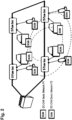
- Each CAN controller is connected to its corresponding DCAN device (see Fig. 2 and Fig. 3 ), and therefore it has no knowledge if there is ongoing traffic on the power line.
- the DCAN devices are connected to the power line, and therefore know if the power line is busy (traffic is ongoing).
- a specific CAN controller wishes to transmit a CAN message when the power line is busy, it is up to the corresponding DCAN device to "inform" this CAN controller that it cannot send any data at this time. This can only be achieved while adhering to the CAN protocol according to the present invention.
- a message will always win the local CAN arbitration with its CAN controller, imposing an artificial delay in the CAN controller TX flow.
- case 1 if it is detected that the CAN controller initiates a new CAN message transfer while previous CAN message is still being transmitted over the power line (busy PL).
- the DUMMY-MSG will make the CAN controller lose arbitration over the CAN bus, and it will have to wait for the duration of the DUMMY-MSG and become a receiver node. Therefore, bus congestions can be avoided as no transmission will occur until the PL bus is in an idle mode.
- case 2 when the CAN controller initiates a new CAN message while the corresponding DCAN device is in the process of PL frame reception from the power line; in this case, the DCAN-generated DUMMY-MSG, will make the corresponding CAN controller wait until completion of power line PL Frame reception.
- the DCAN node according to the invention will always generate DUMMY-MSGs for as long as the power line is not idle and while the CAN controller tries to initiate a new CAN message transfer.
- RX flow receive flow
- the DCAN device Upon detecting a power line PL-Frame, the DCAN device will convert the PL-frame into a CAN message, and then send it to the corresponding CAN controller over the local CAN bus (local link), see Fig. 3 , especially CAN RX input of the local CAN node.
- a CAN controller - DCAN device conflict can occur when in an event where the CAN controller begins transferring CAN message to the corresponding DCAN device while the DCAN device simultaneously begins transferring its received power line PL-Frame to the said CAN controller.
- a method for resolving such conflict by initiating a local CAN-bus arbitration process between said CAN controller and the corresponding DCAN device. If the CAN controller wins the local arbitration, the DCAN device will stop its transfer of the power line PL-Frame and receive the controller's CAN message for later transmission over the power line. Then, the DCAN will automatically transfer that power line CAN message to the corresponding CAN controller.
- CAN controller When the CAN controller loses the local CAN-bus arbitration to the DCAN device, the power line PL-Frame will be fully transferred to the CAN controller. Then, CAN controller may transfer that CAN message or it can be discarded according to a possible implementation.
- Fig 7 illustrates how the corresponding CAN controller transmits consecutive CAN messages according to one possible implementation.
- a CAN protocol that defines 3-bit minimal time between two consecutive transmissions is assumed.
- Example 1 the DCAN device issues a DUMMY-MSG (empty message) to its CAN controller to delay the transfer of a new message until completion of the ongoing CAN power line transmission.
- Example 1 - Fig. 6 depicts two CAN messages A and B with a delay of less than 400 ⁇ s.
- CAN message A is still transmitted over the power line, the CAN controller initiates a new message B.
- SOF start-of-frame
- Example 2 - CAN controller generates new SOF while the corresponding DCAN device is in the process of receiving powerline PL-frame from another DCAN node.
- Fig. 7 explains exemplary how the corresponding CAN controller A generates new SOF while its DCAN device is receiving power line PL-frame from another DCAN node B.
- Case A Powerline PL-frame was fully decoded and is ready to be transferred to controller.
- the DCAN start transferring the power line PL-Frame to the CAN controller. If the controller starts at the same time transferring its own CAN message, a local arbitration will take place between the DCAN and the controller (same as performed in CAN-BUS see above). The message with the higher ID priority will win.
- the DCAN In case the DCAN loses the local arbitration, it will receive the CAN message from its CAN controller, and then it will, transmit the controller CAN message over the power line. Then, the DCAN will retransmit its waiting power line PL-Frame to the corresponding controller again.
- Case B Powerline PL-frame is detected but not fully decoded by DCAN device before corresponding CAN controller A new SOF.
- the DCAN has detected a new power line PL-Frame from DCAN B prior to start of a new CAN message from the CAN controller A.
- the DCAN A issues a DUMMY-MSG until the power line is idle again.
- the CAN controller A loses the local arbitration and becomes a receiver.
- the sequence starts when CAN message B is transmitted to the DCAN B node while the power line is idle. After a while, CAN controller A tries to transmit its CAN message A. Due to the fact the DCAN A is already in the process of detecting DCAN B's power line PL-Frame, it will issue DUMMY-MSG to CAN controller A until the power line is idle again.
- DCAN DEV A When DCAN device A is done with receiving DCAN device B PL frame, the DCAN DEV A will start local arbitration with its corresponding controller (CAN controller A). If CAN controller A wins local arbitration, its CAN message is sent over the power line. Then, DCAN device A re-transmit DEV B MSG to its controller successfully. Controller DEV B receives successfully DEV A CAN MSG.
- DCAN devices making use of the methodology of the present invention can be implemented as a FPGA semiconductor with hard logic programming, as a Digital Signal processor (DSP), or otherwise in application-specific (ASIC) semiconductor or the like.
- DSP Digital Signal processor
- ASIC application-specific
- a device comprising means A and B should not be limited to devices or modules consisting only of components A and B. It means that with respect to the present invention, the only relevant components of the device are A and B.
- a data system adapted to communicate according to a method for performing message arbitration in a first communication network on the basis of physical arbitration of a second communication network.
- the first communication network comprises a plurality of first nodes which are in turn interconnected with corresponding second nodes of the second communication network.
- the method according to the present invention comprises in a first step receiving a message from a first node at a corresponding second node, wherein the message comprises arbitration data of said first communication network. Based on the received message data generating a message-frame at said second node follows.
- the message-frame includes a start preamble comprising a modified arbitration sequence of said first communication network and (upon successful arbitration) subsequently transmitting of the message-frame over the second communication network is provided.
- the method according to the present invention ensures arbitration on one medium i.e. network when the original message arbitration is performed on a different, second medium.
- the aforementioned networks or media can be wire based or wireless. Both technologies can benefit from the methodology according to the present invention.
Landscapes
- Engineering & Computer Science (AREA)
- Computer Networks & Wireless Communication (AREA)
- Signal Processing (AREA)
- Computer Security & Cryptography (AREA)
- Health & Medical Sciences (AREA)
- Cardiology (AREA)
- General Health & Medical Sciences (AREA)
- Small-Scale Networks (AREA)
Claims (13)
- Verfahren zur Durchführung einer Nachrichtenarbitrierung in einem ersten Kommunikationsnetz (CAN-Netzwerk), wobei das erste Kommunikationsnetz ein CAN-Netzwerk ist, basierend auf einer physikalischen Arbitrierung eines physikalisch vorhandenen zweiten Kommunikationsnetzes (PL), wobei das zweite Kommunikationsnetz ein Energieverteilungsnetz ist, wobei das erste Kommunikationsnetz eine Mehrzahl erster Knoten (CAN-Controller) aufweist, wobei die ersten Knoten CAN-Controller sind, die ihrerseits mit entsprechenden zweiten Knoten (DCAN-Geräten) des zweiten Kommunikationsnetzes (PL) verbunden sind, wobei die zweiten Knoten DCAN-Geräte sind, die dafür ausgelegt sind, CAN-Protokoll-kompatiblen Datenverkehr in Energieverteilungs-Protokoll-kompatiblen Datenverkehr umzuwandeln, das Verfahren aufweisend:- Empfangen einer Nachricht von einem ersten Knoten (CAN-Controller) an einem entsprechenden zweiten Knoten (DCAN-Gerät), wobei die Nachricht Arbitrierungsdaten des ersten Kommunikationsnetzes (CAN-Netzwerk) aufweist;- Erzeugen eines Nachrichtenrahmens an dem zweiten Knoten (DCAN-Gerät), wobei der Nachrichtenrahmen eine Startpräambel (Rahmen-Start) hat, die eine modifizierte Arbitrierungssequenz des ersten Kommunikationsnetzes (CAN-Netzwerks) aufweist, wobei die modifizierte Arbitrierungssequenz basierend auf einer grenzüberschreitenden Arbitrierung, das heißt, einer doppelten Arbitrierung über unterschiedliche Arten von Netzwerken hinweg, erzeugt wird, wobei die modifizierte Arbitrierungssequenz einer bitweisen Ersetzung von Arbitrierungsdaten des ersten Kommunikationsnetzes (CAN-Netzwerks), die an das physikalisch vorhandene zweite Kommunikationsnetz (PL) angepasst sind, entspricht; und- Übertragen des Nachrichtenrahmens über das zweite Kommunikationsnetz (PL) mittels des entsprechenden zweiten Knotens (DCAN-Gerät).
- Verfahren nach Anspruch 1, wobei der erzeugte Nachrichtenrahmen ferner mindestens einen Datensatz (Datenpaket), Fehlerkorrekturcodeinformationen (ECC-Bits), und ein Nachrichtensuffix (Rahmen-Ende) aufweist.
- Verfahren nach Anspruch 1 oder 2, wobei der zweite Knoten (DCAN-Gerät) dafür ausgelegt ist, eine Datenübertragung in dem zweiten Kommunikationsnetz (PL) zu erkennen und seinerseits den entsprechenden ersten Knoten (CAN-Controller) zu informieren, das Senden von Nachrichten auszusetzen.
- Verfahren nach einem der vorhergehenden Ansprüche, wobei der zweite Knoten (DCAN-Gerät) eine reservierte Nachricht (DUMMY-MSG) an den entsprechenden ersten Knoten (CAN-Controller) sendet, nachdem er eine Datenübertragung im zweiten Kommunikationsnetz (PL) erkannt hat, wobei die reservierte Nachricht ein Unterliegen in der Arbitrierungsprozedur des ersten Knotens (CAN-Controller) innerhalb des ersten Kommunikationsnetzes (CAN-Netz) bewirkt.
- Verfahren nach einem der vorhergehenden Ansprüche, wobei die Übertragung erkannter Daten einem Datenverkehr innerhalb des zweiten Kommunikationsnetzes (PL) und/oder einem Datenverkehr des entsprechenden Knotens (CAN-Controller) innerhalb des ersten Datenkommunikationsnetzes (CAN-Netzwerk) entspricht.
- Verfahren nach einem der vorhergehenden Ansprüche, ferner aufweisend Erkennen eines Netzwerkkonflikts des zweiten Datenkommunikationsnetzes (PL) und Senden der reservierten Nachricht (DUMMY-MSG) an den entsprechenden ersten Knoten (CAN-Controller).
- Verfahren nach einem der vorhergehenden Ansprüche, wobei das zweite Datenkommunikationsnetz (PL) ein drahtgebundener Kommunikationskanal oder ein drahtloser Kommunikationskanal ist.
- Verfahren nach einem der vorhergehenden Ansprüche, wobei das erste Datenkommunikationsnetz (CAN-Netzwerk) ein protokollbasiertes CAN- (Controller Area Network) Bus-Netzwerk (CAN-Netzwerk) ist.
- Protokollbasiertes Datenübertragungssystem, aufweisend eine Mehrzahl von ersten Knoten (CAN-Controllern), wobei die ersten Knoten CAN-Controller sind, und eine Mehrzahl von zweiten Knoten (DCAN-Geräten), wobei die zweiten Knoten erforderlich sind, um mittels eines zweiten Kommunikationsnetzes (PL) zu kommunizieren, wobei die zweiten Knoten DCAN-Geräte sind, die dafür ausgelegt sind, CAN-Protokoll-kompatiblen Verkehr in Energieverteilungs-Protokoll-kompatiblen Verkehr umzuwandeln, und wobei die ersten Knoten und die zweiten Knoten dafür ausgelegt sind, gemäß dem Verfahren eines der vorstehenden Ansprüche zu kommunizieren.
- Datensystem nach Anspruch 9, wobei der erste Knoten (CAN-Controller) eine Kommunikationsschnittstelle zur Kommunikation mit dem entsprechenden zweiten Knoten (DCAN-Geräte) unter Verwendung des ersten Netzwerkprotokolls aufweist.
- Datensystem nach Anspruch 9 oder 10, wobei die zweiten Knoten (DCAN-Geräte) eine erste Kommunikationsschnittstelle zur Kommunikation mit dem entsprechenden ersten Knoten (CAN-Controller) unter Verwendung eines ersten Netzwerkprotokolls und eine zweite Kommunikationsschnittstelle zur Kommunikation über ein zweites Kommunikationsnetz (PL) und/oder ein drahtloses Netzwerk unter Verwendung eines zweiten Netzwerkprotokolls aufweist.
- Datensystem nach einem der Ansprüche 9 bis 11, wobei die erste Kommunikationsschnittstelle ein CAN, CAN FD, Hochgeschwindigkeits-CAN, oder eine Remote-Geräteverwaltung (Remote Device Management, RDM) ist.
- Datensystem nach einem der Ansprüche 9 bis 12, wobei das drahtlose Netzwerk ein WiFi-Netzwerk, ein 5G-Netzwerk oder ein Bluetooth-Netzwerk ist.
Priority Applications (3)
| Application Number | Priority Date | Filing Date | Title |
|---|---|---|---|
| EP19191153.6A EP3780507B1 (de) | 2019-08-11 | 2019-08-11 | Verfahren und system zur durchführung doppelter nachrichtenarbitrierung |
| CN202010802937.6A CN112398901B (zh) | 2019-08-11 | 2020-08-11 | 执行双报文仲裁的方法和系统 |
| US16/990,104 US20210044450A1 (en) | 2019-08-11 | 2020-08-11 | Method and system for performing double message arbitration |
Applications Claiming Priority (1)
| Application Number | Priority Date | Filing Date | Title |
|---|---|---|---|
| EP19191153.6A EP3780507B1 (de) | 2019-08-11 | 2019-08-11 | Verfahren und system zur durchführung doppelter nachrichtenarbitrierung |
Publications (2)
| Publication Number | Publication Date |
|---|---|
| EP3780507A1 EP3780507A1 (de) | 2021-02-17 |
| EP3780507B1 true EP3780507B1 (de) | 2024-09-18 |
Family
ID=67658655
Family Applications (1)
| Application Number | Title | Priority Date | Filing Date |
|---|---|---|---|
| EP19191153.6A Active EP3780507B1 (de) | 2019-08-11 | 2019-08-11 | Verfahren und system zur durchführung doppelter nachrichtenarbitrierung |
Country Status (3)
| Country | Link |
|---|---|
| US (1) | US20210044450A1 (de) |
| EP (1) | EP3780507B1 (de) |
| CN (1) | CN112398901B (de) |
Families Citing this family (4)
| Publication number | Priority date | Publication date | Assignee | Title |
|---|---|---|---|---|
| CN114760227B (zh) * | 2021-03-16 | 2023-02-28 | 广州汽车集团股份有限公司 | 报文发送延时测试方法、测试上位机和存储介质 |
| CN116488953B (zh) * | 2022-01-14 | 2025-09-05 | 华为技术有限公司 | Can通信方法、电子设备及can通信系统 |
| CN116527441B (zh) * | 2023-05-16 | 2025-07-25 | 中车大连机车车辆有限公司 | 一种基于网络时序仲裁的环形can总线通信方法 |
| US12314210B2 (en) | 2023-05-18 | 2025-05-27 | Toyota Motor North America, Inc. | Virtual can bus |
Family Cites Families (11)
| Publication number | Priority date | Publication date | Assignee | Title |
|---|---|---|---|---|
| US7570597B2 (en) * | 2003-06-12 | 2009-08-04 | Temic Automotive Of North America, Inc. | Discovery process in a vehicle network |
| GB2439126A (en) * | 2006-06-13 | 2007-12-19 | Siconnect Ltd | Non-destructive bit-wise arbitration over noisy communication channels |
| AT504018A1 (de) * | 2006-07-05 | 2008-02-15 | Tttech Computertechnik Ag | Verfahren und einrichtung zum aufbau eines kommunikationssystems auf der basis von can kommunikationskontrollern mit erhöhtem datendurchsatz |
| US7783808B2 (en) * | 2006-11-08 | 2010-08-24 | Honeywell International Inc. | Embedded self-checking asynchronous pipelined enforcement (escape) |
| CN101342891B (zh) * | 2008-07-08 | 2010-09-08 | 奇瑞汽车股份有限公司 | 一种基于can总线的多节点整车网络控制系统 |
| EP2521319B1 (de) * | 2011-05-02 | 2015-10-14 | Robert Bosch GmbH | CAN mit flexibler Datenrate |
| DE102012215765A1 (de) * | 2012-09-05 | 2014-05-15 | Robert Bosch Gmbh | Gateway-Modul für ein Kommunikationssystem, Kommunikationssystem und Verfahren zur Übertragung von Daten zwischen Teilnehmern eines Kommunikationssystems |
| KR101519793B1 (ko) * | 2014-06-24 | 2015-05-12 | 현대자동차주식회사 | 차량용 네트워크 시스템 및 이 시스템 내 이종 통신 제어기의 데이터 전송 방법 |
| EP3160072B1 (de) * | 2015-10-19 | 2019-10-02 | Yamar Electronics Ltd. | Sender-empfänger für asynchrone datenübertragung über einen rauschenden kanal |
| US10880409B2 (en) * | 2017-02-20 | 2020-12-29 | Cisco Technology, Inc. | Mixed qualitative, quantitative sensing data compression over a network transport |
| EP3729766A1 (de) * | 2017-12-24 | 2020-10-28 | Arilou Information Security Technologies Ltd. | System und verfahren zur tunnel-basierten erkennung von schadprogrammen |
-
2019
- 2019-08-11 EP EP19191153.6A patent/EP3780507B1/de active Active
-
2020
- 2020-08-11 CN CN202010802937.6A patent/CN112398901B/zh active Active
- 2020-08-11 US US16/990,104 patent/US20210044450A1/en not_active Abandoned
Also Published As
| Publication number | Publication date |
|---|---|
| US20210044450A1 (en) | 2021-02-11 |
| CN112398901A (zh) | 2021-02-23 |
| CN112398901B (zh) | 2024-04-02 |
| EP3780507A1 (de) | 2021-02-17 |
Similar Documents
| Publication | Publication Date | Title |
|---|---|---|
| US10530606B2 (en) | Method for transmitting data via a serial communication bus, bus interface, and computer program | |
| US20210044450A1 (en) | Method and system for performing double message arbitration | |
| KR101519793B1 (ko) | 차량용 네트워크 시스템 및 이 시스템 내 이종 통신 제어기의 데이터 전송 방법 | |
| KR101462553B1 (ko) | 이더넷을 이용한 제어기 영역 네트워크 통신들 | |
| US6192422B1 (en) | Repeater with flow control device transmitting congestion indication data from output port buffer to associated network node upon port input buffer crossing threshold level | |
| JP5014489B2 (ja) | 確定的通信システム | |
| US20150339254A1 (en) | Data Transmission Using A Protocol Exception State | |
| US20080192772A1 (en) | Low-Weight Hybrid Deterministic Highspeed Data Bus | |
| CN110784385B (zh) | 用于在多主机总线上传送数据帧的方法和装置 | |
| US10055374B2 (en) | Participating station for a bus system and method for data transmission in a bus system | |
| WO2017090351A1 (ja) | 車載ゲートウェイ装置、電子制御装置、車載ネットワークシステム | |
| CN112823496B (zh) | 帧屏蔽单元、用于串行总线系统的用户站以及用于在串行总线系统中进行通信的方法 | |
| CN102804159A (zh) | 用于在总线系统的用户站之间传输数据的方法 | |
| US20240333660A1 (en) | Vehicle network and method of communication | |
| WO2011017997A1 (zh) | 通讯总线控制方法和装置 | |
| JP2012530312A (ja) | バスシステム及び通信装置のための媒体アクセス制御方法 | |
| CN110266568B (zh) | 串行总线系统的成员站和串行总线系统中数据传输的方法 | |
| Min et al. | Interrupt-enabled physical layer collision avoidance for 10base-t1s automotive ethernet | |
| JP2006109258A (ja) | 通信方法及び通信装置 | |
| Dhanush et al. | Enhancing In-Vehicle Networks with CAN-FD: A study of Protocol Improvements over Classical CAN | |
| US12632408B2 (en) | Subscriber station and method for deterministic communication in a serial bus system | |
| KR101514398B1 (ko) | 가상 버스 개념의 차량용 게이트웨이 및 이의 메시지 전송 방법 | |
| KR102945161B1 (ko) | 차량 네트워크에서 수행되는 데이터 스트림 송수신 방법 및 장치 | |
| KR102236241B1 (ko) | 이종의 통신방식들의 노드들이 단일 버스를 공유하여 통신할 수 있게 하는 방법과 기기, 그리고 그 방법에 의해 구축된 네트워크 | |
| CN111314192A (zh) | 一种高速总线结构和通信节点间传输数据的方法 |
Legal Events
| Date | Code | Title | Description |
|---|---|---|---|
| PUAI | Public reference made under article 153(3) epc to a published international application that has entered the european phase |
Free format text: ORIGINAL CODE: 0009012 |
|
| STAA | Information on the status of an ep patent application or granted ep patent |
Free format text: STATUS: THE APPLICATION HAS BEEN PUBLISHED |
|
| AK | Designated contracting states |
Kind code of ref document: A1 Designated state(s): AL AT BE BG CH CY CZ DE DK EE ES FI FR GB GR HR HU IE IS IT LI LT LU LV MC MK MT NL NO PL PT RO RS SE SI SK SM TR |
|
| AX | Request for extension of the european patent |
Extension state: BA ME |
|
| STAA | Information on the status of an ep patent application or granted ep patent |
Free format text: STATUS: REQUEST FOR EXAMINATION WAS MADE |
|
| 17P | Request for examination filed |
Effective date: 20210805 |
|
| RBV | Designated contracting states (corrected) |
Designated state(s): AL AT BE BG CH CY CZ DE DK EE ES FI FR GB GR HR HU IE IS IT LI LT LU LV MC MK MT NL NO PL PT RO RS SE SI SK SM TR |
|
| STAA | Information on the status of an ep patent application or granted ep patent |
Free format text: STATUS: EXAMINATION IS IN PROGRESS |
|
| 17Q | First examination report despatched |
Effective date: 20220504 |
|
| GRAP | Despatch of communication of intention to grant a patent |
Free format text: ORIGINAL CODE: EPIDOSNIGR1 |
|
| STAA | Information on the status of an ep patent application or granted ep patent |
Free format text: STATUS: GRANT OF PATENT IS INTENDED |
|
| INTG | Intention to grant announced |
Effective date: 20240424 |
|
| GRAS | Grant fee paid |
Free format text: ORIGINAL CODE: EPIDOSNIGR3 |
|
| GRAA | (expected) grant |
Free format text: ORIGINAL CODE: 0009210 |
|
| STAA | Information on the status of an ep patent application or granted ep patent |
Free format text: STATUS: THE PATENT HAS BEEN GRANTED |
|
| AK | Designated contracting states |
Kind code of ref document: B1 Designated state(s): AL AT BE BG CH CY CZ DE DK EE ES FI FR GB GR HR HU IE IS IT LI LT LU LV MC MK MT NL NO PL PT RO RS SE SI SK SM TR |
|
| REG | Reference to a national code |
Ref country code: GB Ref legal event code: FG4D |
|
| REG | Reference to a national code |
Ref country code: CH Ref legal event code: EP |
|
| REG | Reference to a national code |
Ref country code: DE Ref legal event code: R096 Ref document number: 602019059008 Country of ref document: DE |
|
| REG | Reference to a national code |
Ref country code: IE Ref legal event code: FG4D |
|
| REG | Reference to a national code |
Ref country code: LT Ref legal event code: MG9D |
|
| PG25 | Lapsed in a contracting state [announced via postgrant information from national office to epo] |
Ref country code: NO Free format text: LAPSE BECAUSE OF FAILURE TO SUBMIT A TRANSLATION OF THE DESCRIPTION OR TO PAY THE FEE WITHIN THE PRESCRIBED TIME-LIMIT Effective date: 20241218 |
|
| PG25 | Lapsed in a contracting state [announced via postgrant information from national office to epo] |
Ref country code: GR Free format text: LAPSE BECAUSE OF FAILURE TO SUBMIT A TRANSLATION OF THE DESCRIPTION OR TO PAY THE FEE WITHIN THE PRESCRIBED TIME-LIMIT Effective date: 20241219 Ref country code: FI Free format text: LAPSE BECAUSE OF FAILURE TO SUBMIT A TRANSLATION OF THE DESCRIPTION OR TO PAY THE FEE WITHIN THE PRESCRIBED TIME-LIMIT Effective date: 20240918 |
|
| PG25 | Lapsed in a contracting state [announced via postgrant information from national office to epo] |
Ref country code: BG Free format text: LAPSE BECAUSE OF FAILURE TO SUBMIT A TRANSLATION OF THE DESCRIPTION OR TO PAY THE FEE WITHIN THE PRESCRIBED TIME-LIMIT Effective date: 20240918 |
|
| PG25 | Lapsed in a contracting state [announced via postgrant information from national office to epo] |
Ref country code: LV Free format text: LAPSE BECAUSE OF FAILURE TO SUBMIT A TRANSLATION OF THE DESCRIPTION OR TO PAY THE FEE WITHIN THE PRESCRIBED TIME-LIMIT Effective date: 20240918 |
|
| PG25 | Lapsed in a contracting state [announced via postgrant information from national office to epo] |
Ref country code: HR Free format text: LAPSE BECAUSE OF FAILURE TO SUBMIT A TRANSLATION OF THE DESCRIPTION OR TO PAY THE FEE WITHIN THE PRESCRIBED TIME-LIMIT Effective date: 20240918 |
|
| REG | Reference to a national code |
Ref country code: NL Ref legal event code: MP Effective date: 20240918 |
|
| PG25 | Lapsed in a contracting state [announced via postgrant information from national office to epo] |
Ref country code: RS Free format text: LAPSE BECAUSE OF FAILURE TO SUBMIT A TRANSLATION OF THE DESCRIPTION OR TO PAY THE FEE WITHIN THE PRESCRIBED TIME-LIMIT Effective date: 20241218 |
|
| PG25 | Lapsed in a contracting state [announced via postgrant information from national office to epo] |
Ref country code: RS Free format text: LAPSE BECAUSE OF FAILURE TO SUBMIT A TRANSLATION OF THE DESCRIPTION OR TO PAY THE FEE WITHIN THE PRESCRIBED TIME-LIMIT Effective date: 20241218 Ref country code: NO Free format text: LAPSE BECAUSE OF FAILURE TO SUBMIT A TRANSLATION OF THE DESCRIPTION OR TO PAY THE FEE WITHIN THE PRESCRIBED TIME-LIMIT Effective date: 20241218 Ref country code: LV Free format text: LAPSE BECAUSE OF FAILURE TO SUBMIT A TRANSLATION OF THE DESCRIPTION OR TO PAY THE FEE WITHIN THE PRESCRIBED TIME-LIMIT Effective date: 20240918 Ref country code: HR Free format text: LAPSE BECAUSE OF FAILURE TO SUBMIT A TRANSLATION OF THE DESCRIPTION OR TO PAY THE FEE WITHIN THE PRESCRIBED TIME-LIMIT Effective date: 20240918 Ref country code: GR Free format text: LAPSE BECAUSE OF FAILURE TO SUBMIT A TRANSLATION OF THE DESCRIPTION OR TO PAY THE FEE WITHIN THE PRESCRIBED TIME-LIMIT Effective date: 20241219 Ref country code: FI Free format text: LAPSE BECAUSE OF FAILURE TO SUBMIT A TRANSLATION OF THE DESCRIPTION OR TO PAY THE FEE WITHIN THE PRESCRIBED TIME-LIMIT Effective date: 20240918 Ref country code: BG Free format text: LAPSE BECAUSE OF FAILURE TO SUBMIT A TRANSLATION OF THE DESCRIPTION OR TO PAY THE FEE WITHIN THE PRESCRIBED TIME-LIMIT Effective date: 20240918 |
|
| REG | Reference to a national code |
Ref country code: AT Ref legal event code: MK05 Ref document number: 1725623 Country of ref document: AT Kind code of ref document: T Effective date: 20240918 |
|
| PG25 | Lapsed in a contracting state [announced via postgrant information from national office to epo] |
Ref country code: NL Free format text: LAPSE BECAUSE OF FAILURE TO SUBMIT A TRANSLATION OF THE DESCRIPTION OR TO PAY THE FEE WITHIN THE PRESCRIBED TIME-LIMIT Effective date: 20240918 |
|
| REG | Reference to a national code |
Ref country code: DE Ref legal event code: R082 Ref document number: 602019059008 Country of ref document: DE Representative=s name: HEILEIN IP LAW, DE |
|
| PG25 | Lapsed in a contracting state [announced via postgrant information from national office to epo] |
Ref country code: PT Free format text: LAPSE BECAUSE OF FAILURE TO SUBMIT A TRANSLATION OF THE DESCRIPTION OR TO PAY THE FEE WITHIN THE PRESCRIBED TIME-LIMIT Effective date: 20250120 Ref country code: IS Free format text: LAPSE BECAUSE OF FAILURE TO SUBMIT A TRANSLATION OF THE DESCRIPTION OR TO PAY THE FEE WITHIN THE PRESCRIBED TIME-LIMIT Effective date: 20250118 |
|
| PG25 | Lapsed in a contracting state [announced via postgrant information from national office to epo] |
Ref country code: RO Free format text: LAPSE BECAUSE OF FAILURE TO SUBMIT A TRANSLATION OF THE DESCRIPTION OR TO PAY THE FEE WITHIN THE PRESCRIBED TIME-LIMIT Effective date: 20240918 Ref country code: SM Free format text: LAPSE BECAUSE OF FAILURE TO SUBMIT A TRANSLATION OF THE DESCRIPTION OR TO PAY THE FEE WITHIN THE PRESCRIBED TIME-LIMIT Effective date: 20240918 |
|
| PG25 | Lapsed in a contracting state [announced via postgrant information from national office to epo] |
Ref country code: ES Free format text: LAPSE BECAUSE OF FAILURE TO SUBMIT A TRANSLATION OF THE DESCRIPTION OR TO PAY THE FEE WITHIN THE PRESCRIBED TIME-LIMIT Effective date: 20240918 |
|
| PG25 | Lapsed in a contracting state [announced via postgrant information from national office to epo] |
Ref country code: EE Free format text: LAPSE BECAUSE OF FAILURE TO SUBMIT A TRANSLATION OF THE DESCRIPTION OR TO PAY THE FEE WITHIN THE PRESCRIBED TIME-LIMIT Effective date: 20240918 Ref country code: AT Free format text: LAPSE BECAUSE OF FAILURE TO SUBMIT A TRANSLATION OF THE DESCRIPTION OR TO PAY THE FEE WITHIN THE PRESCRIBED TIME-LIMIT Effective date: 20240918 |
|
| PG25 | Lapsed in a contracting state [announced via postgrant information from national office to epo] |
Ref country code: CZ Free format text: LAPSE BECAUSE OF FAILURE TO SUBMIT A TRANSLATION OF THE DESCRIPTION OR TO PAY THE FEE WITHIN THE PRESCRIBED TIME-LIMIT Effective date: 20240918 Ref country code: PL Free format text: LAPSE BECAUSE OF FAILURE TO SUBMIT A TRANSLATION OF THE DESCRIPTION OR TO PAY THE FEE WITHIN THE PRESCRIBED TIME-LIMIT Effective date: 20240918 |
|
| PG25 | Lapsed in a contracting state [announced via postgrant information from national office to epo] |
Ref country code: SK Free format text: LAPSE BECAUSE OF FAILURE TO SUBMIT A TRANSLATION OF THE DESCRIPTION OR TO PAY THE FEE WITHIN THE PRESCRIBED TIME-LIMIT Effective date: 20240918 Ref country code: IT Free format text: LAPSE BECAUSE OF FAILURE TO SUBMIT A TRANSLATION OF THE DESCRIPTION OR TO PAY THE FEE WITHIN THE PRESCRIBED TIME-LIMIT Effective date: 20240918 |
|
| REG | Reference to a national code |
Ref country code: DE Ref legal event code: R097 Ref document number: 602019059008 Country of ref document: DE |
|
| PG25 | Lapsed in a contracting state [announced via postgrant information from national office to epo] |
Ref country code: DK Free format text: LAPSE BECAUSE OF FAILURE TO SUBMIT A TRANSLATION OF THE DESCRIPTION OR TO PAY THE FEE WITHIN THE PRESCRIBED TIME-LIMIT Effective date: 20240918 |
|
| PLBE | No opposition filed within time limit |
Free format text: ORIGINAL CODE: 0009261 |
|
| STAA | Information on the status of an ep patent application or granted ep patent |
Free format text: STATUS: NO OPPOSITION FILED WITHIN TIME LIMIT |
|
| 26N | No opposition filed |
Effective date: 20250619 |
|
| PG25 | Lapsed in a contracting state [announced via postgrant information from national office to epo] |
Ref country code: SE Free format text: LAPSE BECAUSE OF FAILURE TO SUBMIT A TRANSLATION OF THE DESCRIPTION OR TO PAY THE FEE WITHIN THE PRESCRIBED TIME-LIMIT Effective date: 20240918 |
|
| PGFP | Annual fee paid to national office [announced via postgrant information from national office to epo] |
Ref country code: GB Payment date: 20250729 Year of fee payment: 7 |
|
| PGFP | Annual fee paid to national office [announced via postgrant information from national office to epo] |
Ref country code: FR Payment date: 20250821 Year of fee payment: 7 |
|
| PGFP | Annual fee paid to national office [announced via postgrant information from national office to epo] |
Ref country code: DE Payment date: 20251022 Year of fee payment: 7 |
|
| REG | Reference to a national code |
Ref country code: CH Ref legal event code: H13 Free format text: ST27 STATUS EVENT CODE: U-0-0-H10-H13 (AS PROVIDED BY THE NATIONAL OFFICE) Effective date: 20260324 |
|
| PG25 | Lapsed in a contracting state [announced via postgrant information from national office to epo] |
Ref country code: MC Free format text: LAPSE BECAUSE OF FAILURE TO SUBMIT A TRANSLATION OF THE DESCRIPTION OR TO PAY THE FEE WITHIN THE PRESCRIBED TIME-LIMIT Effective date: 20240918 |
|
| PG25 | Lapsed in a contracting state [announced via postgrant information from national office to epo] |
Ref country code: LU Free format text: LAPSE BECAUSE OF NON-PAYMENT OF DUE FEES Effective date: 20250811 |
|
| PG25 | Lapsed in a contracting state [announced via postgrant information from national office to epo] |
Ref country code: CH Free format text: LAPSE BECAUSE OF NON-PAYMENT OF DUE FEES Effective date: 20250831 |