EP3780530A1 - Benutzergerät und basisstationsvorrichtung - Google Patents
Benutzergerät und basisstationsvorrichtung Download PDFInfo
- Publication number
- EP3780530A1 EP3780530A1 EP18911793.0A EP18911793A EP3780530A1 EP 3780530 A1 EP3780530 A1 EP 3780530A1 EP 18911793 A EP18911793 A EP 18911793A EP 3780530 A1 EP3780530 A1 EP 3780530A1
- Authority
- EP
- European Patent Office
- Prior art keywords
- pusch
- reference signal
- demodulation reference
- frequency hopping
- user equipment
- Prior art date
- Legal status (The legal status is an assumption and is not a legal conclusion. Google has not performed a legal analysis and makes no representation as to the accuracy of the status listed.)
- Pending
Links
Images







Classifications
-
- H—ELECTRICITY
- H04—ELECTRIC COMMUNICATION TECHNIQUE
- H04L—TRANSMISSION OF DIGITAL INFORMATION, e.g. TELEGRAPHIC COMMUNICATION
- H04L5/00—Arrangements affording multiple use of the transmission path
- H04L5/0001—Arrangements for dividing the transmission path
- H04L5/0003—Two-dimensional division
- H04L5/0005—Time-frequency
- H04L5/0007—Time-frequency the frequencies being orthogonal, e.g. OFDM(A) or DMT
- H04L5/0012—Hopping in multicarrier systems
-
- H—ELECTRICITY
- H04—ELECTRIC COMMUNICATION TECHNIQUE
- H04B—TRANSMISSION
- H04B1/00—Details of transmission systems, not covered by a single one of groups H04B3/00 - H04B13/00; Details of transmission systems not characterised by the medium used for transmission
- H04B1/69—Spread spectrum techniques
- H04B1/713—Spread spectrum techniques using frequency hopping
-
- H—ELECTRICITY
- H04—ELECTRIC COMMUNICATION TECHNIQUE
- H04L—TRANSMISSION OF DIGITAL INFORMATION, e.g. TELEGRAPHIC COMMUNICATION
- H04L27/00—Modulated-carrier systems
- H04L27/26—Systems using multi-frequency codes
- H04L27/2601—Multicarrier modulation systems
- H04L27/2602—Signal structure
- H04L27/261—Details of reference signals
- H04L27/2613—Structure of the reference signals
-
- H—ELECTRICITY
- H04—ELECTRIC COMMUNICATION TECHNIQUE
- H04L—TRANSMISSION OF DIGITAL INFORMATION, e.g. TELEGRAPHIC COMMUNICATION
- H04L5/00—Arrangements affording multiple use of the transmission path
- H04L5/003—Arrangements for allocating sub-channels of the transmission path
- H04L5/0044—Allocation of payload; Allocation of data channels, e.g. PDSCH or PUSCH
-
- H—ELECTRICITY
- H04—ELECTRIC COMMUNICATION TECHNIQUE
- H04L—TRANSMISSION OF DIGITAL INFORMATION, e.g. TELEGRAPHIC COMMUNICATION
- H04L5/00—Arrangements affording multiple use of the transmission path
- H04L5/003—Arrangements for allocating sub-channels of the transmission path
- H04L5/0048—Allocation of pilot signals, i.e. of signals known to the receiver
Definitions
- the present invention relates to a user equipment and a base station apparatus in a wireless communication system.
- NR New Radio
- DM-RS demodulation reference signal
- front-loaded DM-RS DM-RS arranged on a frontward position in the time domain of a slot.
- additional DM-RS DM-RS arranged on a rearward position in the time domain of a slot.
- Non-Patent Document 1 3GPP TS 38.211 V15.0.0 (2017-12 )
- a user equipment that communicates with a base station apparatus, the user equipment including a processing unit, wherein when transmitting a physical uplink shared channel (PUSCH) to the base station apparatus prior to establishment of a radio resource control (RRC) connection between the base station apparatus and the user equipment, the processing unit controls frequency hopping to be applied to the PUSCH and a demodulation reference signal; a reception unit for receiving from the base station apparatus information indicating that frequency hopping to be applied to the PUSCH; and a transmission unit for transmitting the PUSCH and the demodulation reference signal to which frequency hopping has been applied; wherein the demodulation reference signal for demodulating a single PUSCH is formed of one front-loaded demodulation reference signal and one additional demodulation reference signal, and when the duration in symbols of the PUSCH does not support one additional demodulation reference signal, the demodulation reference signal is formed of a front-loaded demodulation reference signal.
- PUSCH physical uplink shared channel
- RRC radio resource control
- frequency hopping can be applied to a demodulation reference signal appropriately in a wireless communication system to obtain a frequency hopping gain.
- a preexisting technique is used as appropriate.
- the preexisting technique may be, but is not limited to, preexisting LTE, for example.
- LTE LTE
- the term "LTE" as used herein should be construed as having a broad meaning including LTE-Advanced and methods after LTE-Advanced (e.g., NR or 5G) .
- synchronization signal SS
- PSS primary SS
- SSS secondary SS
- PBCH physical broadcast channel
- PRACH physical RACH
- a duplex system may be a time division duplex (TDD) system, a frequency division duplex (FDD) system or any other system (e.g., flexible duplex).
- TDD time division duplex
- FDD frequency division duplex
- flexible duplex any other system (e.g., flexible duplex).
- transmitting a signal using a transmission beam may be transmitting a signal multiplied by a precoding vector (pre-coded with a precoding vector).
- receiving a signal using a reception beam may be multiplying a received signal with a predetermined weighted vector.
- transmitting a signal using a transmission beam may be transmitting a signal with a specific antenna port.
- receiving a signal using a reception beam may be receiving a signal with a specific antenna port.
- An antenna port refers to a logical antenna port or a physical antenna port specified in the 3GPP specifications.
- Methods for forming transmission and reception beams are not limited to the above-mentioned methods.
- a method of changing the angle of each antenna may be used, a combination of a method of using a precoding vector and the method of changing antenna angles may be used, different antenna panels may be switched and used, a method of using a combination of a plurality of antenna panels may be used, or any other method may be used.
- a plurality of different transmission beams may be used in a high frequency band. Using a plurality of transmission beams is referred to as a multi-beam operation and using one transmission beam is referred to as a single-beam operation.
- “configuring" wireless parameters or the like may be pre-configuring or specifying predetermined values or may be configuring wireless parameters reported from a base station apparatus 100 or a user equipment 200.
- Fig. 1 is a diagram for illustrating an exemplary configuration of a wireless communication system in an embodiment of the present invention.
- the wireless communication system in the embodiment of the present invention comprises a base station apparatus 100 and a user equipment 200.
- Fig. 1 illustrates one base station apparatus 100 and one user equipment 200, this is merely an example and the wireless communication system may include a plurality of base station apparatuses 100 and a plurality of units of user equipment 200.
- the base station apparatus 100 is a communication device that provides one or more cells and communicates with the user equipment 200 wirelessly.
- the base station apparatus 100 sends a reference signal to the user equipment 200, and the user equipment 200 sends a reference signal to the base station apparatus 100.
- the reference signals are arranged on predetermined orthogonal frequency division multiplexing (OFDM) symbols on a radio frame on which control and data signals are arranged.
- the reference signals include a demodulation reference signal (DM-RS), a phase noise tracking reference signal (PT-RS), a channel status information-reference signal (CSI-RS) and the like.
- the base station apparatus 100 and the user equipment 200 can transmit and receive signals by beamforming.
- the user equipment 200 is a communication device with wireless communication capability, such as a smart phone, a mobile phone, a tablet, a wearable terminal, or a machine-to-machine (M2M) communication module, which is connected to the base station apparatus 100 wirelessly, and uses a variety of communication services provided by the wireless communication system.
- M2M machine-to-machine
- the user equipment 200 On the basis of a reference signal on a radio frame received from the basis station apparatus 100, the user equipment 200 carries out channel estimation and demodulation of a downlink signal.
- the base station apparatus 100 On the other hand, on the basis of a reference signal on a radio frame received from the user equipment 200, the base station apparatus 100 carries out channel estimation and demodulation of an uplink signal.
- NR-PUSCH Physical uplink shared channel
- NR-PUSCH Physical uplink shared channel
- PUSCH Physical uplink shared channel
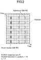
- Fig. 2 is Example (1) of DM-RS arrangement on a radio frame in the embodiment of the present invention.
- One format of mapping DM-RS to OFDM symbols when no frequency hopping is applied in NR will be described.
- the single slot illustrated in Fig. 2 is an example that illustrates, of 14 OFDM symbols, those to which DM-RS is mapped.
- the resource in each symbol is divided into subcarriers, and 12 subcarriers form one resource block.
- the method of mapping PUSCH to physical resources as illustrated in Fig. 2 is referred to as PUSCH mapping type A, in which PUSCH duration in symbols, i.e., the number of symbols in one PUSCH duration, is 14.
- DM-RS is arranged on every other subcarrier, and DM-RS may be arranged at a different density. Although one DM-RS is arranged on one symbol in Fig. 2 , one DM-RS may be arranged on two consecutive symbols. In Fig. 2 , in one PUSCH duration, front-loaded DM-RS is arranged on one symbol and additional DM-RS is arranged on two symbols.
- a data signal within PUSCH is arranged on physical resources where no DM-RS is not arranged. Further, one PUSCH is arranged in the duration of 14 symbols from symbol #0 to symbol #13.
- the DM-RS arranged on the frontward position is front-loaded DM-RS and the DM-RS each arranged on the rearward positions is additional DM-RS. As illustrated in Fig. 2 , front-loaded DM-RS is arranged on symbol #2, and additional DM-RS is arranged on symbol #7 and #11.
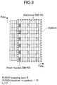
- Fig. 3 is Example (2) of DM-RS arrangement on a radio frame in the embodiment of the present invention. Another format of mapping DM-RS to OFDM symbols when no frequency hopping is applied in NR will be described.
- the single slot illustrated in Fig. 3 is an example that illustrates, of 14 OFDM symbols, those to which DM-RS is mapped.
- the resource in each symbol is divided into subcarriers, and 12 subcarriers form one resource block.
- the method of mapping PUSCH to physical resources as illustrated in Fig. 3 is referred to as PUSCH mapping type B, in which PUSCH duration in symbols, i.e., the number of symbols in one PUSCH duration, is 10.
- I 0 as the position of the symbol on which front-loaded DM-RS corresponding to PUSCH is arranged is "0".
- PUSCH is scheduled in a single slot, and the start symbol of PUSCH is symbol #4.
- front-loaded DM-RS is arranged on one symbol and additional DM-RS is arranged on two symbols.
- a data signal within PUSCH is arranged on physical resources where no DM-RS is not arranged. Further, one PUSCH is arranged in the duration of 10 symbols from symbol #4 to symbol #13.
- the DM-RS arranged on the frontward position is front-loaded DM-RS and the DM-RS each arranged on the rearward positions is additional DM-RS.
- front-loaded DM-RS is arranged on symbol #4. Additional DM-RS is arranged on symbols #8 and #12.
- the symbol where the arrangement of PUSCH starts may be any symbol, and PUSCH may be arranged on symbols from symbol #0 to symbol #9 or from symbol #2 to symbol #11, for example.
- PUSCH is transmitted from the user equipment 200 in a state where it is not scheduled with PDCCH involving cyclic redundancy check (CRC) scrambled with a cell radio network temporary identifier (C-RNTI) or configured scheduling RNTI (CS-RNTI), that is, in a state prior to the establishment of radio resource control (RRC) connection is discussed.
- C-RNTI cell radio network temporary identifier
- CS-RNTI configured scheduling RNTI
- RRC radio resource control
- Table 1 illustrates the positions of DM-RS corresponding to first hop and second hop when applying frequency hopping to PUSCH that is to be transmitted prior to the establishment of RRC connection, where front-loaded DM-RS is arranged on one symbol and the number of additional DM-RS is one. However, when one additional DM-RS is not supported by the PUSCH duration, the positons of DM-RS shown are those with 0 additional DM-RS.
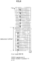
- Fig. 4 is a diagram illustrating Example (1) of frequency hopping in the embodiment of the present invention.
- Fig. 4 illustrates the arrangement of DM-RS where the PUSCH mapping type used is "PUSCH mapping type A" as illustrated in Table 1, the length of PUSCH is scheduled for 8 symbols, the "duration in symbols" of both "first hop” and “second hop” is “4", “first hop” is “I 0 ", and “second hop” is “0".
- front-loaded DM-RS corresponding to first PUSCH as first hop is arranged on symbol #2.
- Front-loaded DM-RS corresponding to second PUSCH as second hop is arranged on symbol #4.
- the arrangement of DM-RS starts from a subcarrier to which frequency offset is applied as a result of the application of frequency hopping.
- DM-RS may be arranged on physical resources resulting from scheduling the length of PUSCH for 7 symbols, setting the “duration in symbols” of “first hop” to “4", and setting the “duration in symbols” of “second hop” to “3", or on physical resources resulting from setting the "duration in symbols” of "first hop” to “3” and the “duration in symbols” of "second hop” is "4".
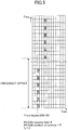
- Fig. 5 is a diagram illustrating Example (2) of frequency hopping in the embodiment of the present invention.
- Fig. 5 illustrates the arrangement of DM-RS where the PUSCH mapping type used is "PUSCH mapping type A" as illustrated in Table 1, the length of PUSCH is scheduled for 10 symbols, the "duration in symbols" of both "first hop” and “second hop” is “5", “first hop” is “I 0 ", and “second hop” is “0".
- front-loaded DM-RS corresponding to first PUSCH as first hop is arranged on symbol #2.
- Front-loaded DM-RS corresponding to second PUSCH as second hop is arranged on symbol #5.
- the arrangement of DM-RS starts from a subcarrier to which frequency offset is applied as a result of the application of frequency hopping.
- Fig. 6 is a diagram illustrating Example (3) of frequency hopping in the embodiment of the present invention.
- Fig. 6 illustrates the arrangement of DM-RS where the PUSCH mapping type used is "PUSCH mapping type A" as illustrated in Table 1, the length of PUSCH is scheduled for 10 symbols, the "duration in symbols" of both "first hop” and “second hop” is “6", “first hop” is “I 0 ", and “second hop” is “0".
- front-loaded DM-RS corresponding to first PUSCH as first hop is arranged on symbol #2.
- Front-loaded DM-RS corresponding to second PUSCH as second hop is arranged on symbol #6.
- the arrangement of DM-RS starts from a subcarrier to which frequency offset is applied as a result of the application of frequency hopping.
- Fig. 7 is a diagram illustrating Example (4) of frequency hopping in the embodiment of the present invention.
- Fig. 7 illustrates the arrangement of DM-RS where the PUSCH mapping type used is "PUSCH mapping type A" as illustrated in Table 1, the length of PUSCH is scheduled for 14 symbols, the "duration in symbols" of both "first hop” and “second hop” is “7", “first hop” is “I 0 " and “I 0 +4", and “second hop” is “0” and “4".
- front-loaded DM-RS and additional DM-RS corresponding to first PUSCH as first hop are arranged on symbol #2 and symbol #6, respectively.
- Front-loaded DM-RS and additional DM-RS corresponding to second PUSCH as second hop are arranged on symbol #7 and symbol #11, respectively.
- the arrangement of DM-RS starts from a subcarrier to which frequency offset is applied as a result of the application of frequency hopping.
- Fig. 8 is a diagram illustrating Example (5) of frequency hopping in the embodiment of the present invention.
- Fig. 8 illustrates the arrangement of DM-RS where the PUSCH mapping type used is "PUSCH mapping type B" as illustrated in Table 1, the length of PUSCH is scheduled for 6 symbols, the "duration in symbols" of both "first hop” and “second hop” is “3", “first hop” is “I 0 ", and “second hop” is “0".
- the PUSCH start symbol is scheduled on symbol #8
- the drawing illustrates the arrangement of DM-RS with respect to a single slot.
- a data signal within PUSCH is arranged on physical resources where no DM-RS is not arranged.
- front-loaded DM-RS corresponding to first PUSCH as first hop is arranged on symbol #8.
- Front-loaded DM-RS corresponding to second PUSCH as second hop is arranged on symbol #11.
- the arrangement of DM-RS starts from a subcarrier to which frequency offset is applied as a result of the application of frequency hopping.
- Fig. 9 is a diagram illustrating Example (6) of frequency hopping in the embodiment of the present invention.
- Fig. 9 illustrates the arrangement of DM-RS where the PUSCH mapping type used is "PUSCH mapping type B" as illustrated in Table 1, the length of PUSCH is scheduled for 8 symbols, the "duration in symbols" of both "first hop” and “second hop” is “4", “first hop” is “I 0 ", and “second hop” is “0".
- the PUSCH start symbol is scheduled on symbol #6, and the drawing illustrates the arrangement of DM-RS with respect to a single slot.
- a data signal within PUSCH is arranged on physical resources where no DM-RS is not arranged.
- front-loaded DM-RS corresponding to first PUSCH as first hop is arranged on symbol #6.
- Front-loaded DM-RS corresponding to second PUSCH as second hop is arranged on symbol #10.
- the arrangement of DM-RS starts from a subcarrier to which frequency offset is applied as a result of the application of frequency hopping.
- Fig. 10 is a diagram illustrating Example (7) of frequency hopping in the embodiment of the present invention.
- Fig. 10 illustrates the arrangement of DM-RS where the PUSCH mapping type used is "PUSCH mapping type B" as illustrated in Table 1, the length of PUSCH is scheduled for 10 symbols, the "duration in symbols" of both "first hop” and “second hop” is “5", “first hop” is “I 0 " and “I 0 +4", and “second hop” is “0” and “4".
- the PUSCH start symbol is scheduled on symbol #4
- the drawing illustrates the arrangement of DM-RS with respect to a single slot.
- a data signal within PUSCH is arranged on physical resources where no DM-RS is not arranged.
- front-loaded DM-RS and additional DM-RS corresponding to first PUSCH as first hop are arranged on symbol #4 and symbol #8, respectively.
- Front-loaded DM-RS and additional DM-RS corresponding to second PUSCH as second hop are arranged on symbol #9 and symbol #13, respectively.
- the arrangement of DM-RS starts from a subcarrier to which frequency offset is applied as a result of the application of frequency hopping.
- Fig. 11 is a diagram illustrating Example (8) of frequency hopping in the embodiment of the present invention.
- Fig. 11 illustrates the arrangement of DM-RS where the PUSCH mapping type used is "PUSCH mapping type B" as illustrated in Table 1, the length of PUSCH is scheduled for 12 symbols, the "duration in symbols" of both "first hop” and “second hop” is “6", “first hop” is “I 0 " and “I 0 +4", and “second hop” is “0” and “4".
- the PUSCH start symbol is scheduled on symbol #2
- the drawing illustrates the arrangement of DM-RS with respect to a single slot.
- a data signal within PUSCH is arranged on physical resources where no DM-RS is not arranged.
- front-loaded DM-RS and additional DM-RS corresponding to first PUSCH as first hop are arranged on symbol #2 and symbol #6, respectively.
- Front-loaded DM-RS and additional DM-RS corresponding to second PUSCH as second hop are arranged on symbol #8 and symbol #12, respectively.
- the arrangement of DM-RS starts from a subcarrier to which frequency offset is applied as a result of the application of frequency hopping.
- Fig. 12 is a diagram illustrating Example (9) of frequency hopping in the embodiment of the present invention.
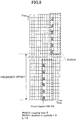
- Fig. 12 illustrates the arrangement of DM-RS where the PUSCH mapping type used is "PUSCH mapping type B" as illustrated in Table 1, the length of PUSCH is scheduled for 14 symbols, the "duration in symbols" of both "first hop” and “second hop” is “7", “first hop” is “I 0 " and “I 0 +4", and “second hop” is “0” and “4".
- the PUSCH start symbol is scheduled on symbol #0
- the drawing illustrates the arrangement of DM-RS with respect to a single slot.
- a data signal within PUSCH is arranged on physical resources where no DM-RS is not arranged.
- front-loaded DM-RS and additional DM-RS corresponding to first PUSCH as first hop are arranged on symbol #0 and symbol #4, respectively.
- Front-loaded DM-RS and additional DM-RS corresponding to second PUSCH as second hop are arranged on symbol #7 and symbol #11, respectively.
- the arrangement of DM-RS starts from a subcarrier to which frequency offset is applied as a result of the application of frequency hopping.
- Table 2 illustrates the positions of DM-RS corresponding to first hop and second hop when applying frequency hopping to PUSCH that is to be transmitted prior to the establishment of RRC connection, where front-loaded DM-RS is arranged on one symbol and the number of additional DM-RS is none.
- Fig. 13 is a diagram illustrating Example (10) of frequency hopping in the embodiment of the present invention.
- Fig. 13 illustrates the arrangement of DM-RS where the PUSCH mapping type used is "PUSCH mapping type A" as illustrated in Table 2, the length of PUSCH is scheduled for 14 symbols, the "duration in symbols" of both "first hop” and “second hop” is “7", “first hop” is “I 0 ", and “second hop” is “0".
- front-loaded DM-RS corresponding to first PUSCH as first hop is arranged on symbol #2.
- Front-loaded DM-RS corresponding to second PUSCH as second hop is arranged on symbol #7.
- the arrangement of DM-RS starts from a subcarrier to which frequency offset is applied as a result of the application of frequency hopping.
- Fig. 14 is a diagram illustrating Example (11) of frequency hopping in the embodiment of the present invention.
- Fig. 14 illustrates the arrangement of DM-RS where the PUSCH mapping type used is "PUSCH mapping type B" as illustrated in Table 2, the length of PUSCH is scheduled for 10 symbols, the “duration in symbols” of both "first hop” and “second hop” is “5", “first hop” is “I 0 ", and “second hop” is “0".
- the PUSCH start symbol is scheduled on symbol #4
- the drawing illustrates the arrangement of DM-RS with respect to a single slot.
- a data signal within PUSCH is arranged on physical resources where no DM-RS is not arranged.
- front-loaded DM-RS corresponding to first PUSCH as first hop is arranged on symbol #4.
- Front-loaded DM-RS corresponding to second PUSCH as second hop is arranged on symbol #9.
- the arrangement of DM-RS starts from a subcarrier to which frequency offset is applied as a result of the application of frequency hopping.
- Fig. 15 is a diagram illustrating Example (12) of frequency hopping in the embodiment of the present invention.
- Fig. 15 illustrates the arrangement of DM-RS where the PUSCH mapping type used is "PUSCH mapping type B" as illustrated in Table 2, the length of PUSCH is scheduled for 12 symbols, the "duration in symbols" of both "first hop” and “second hop” is “6", “first hop” is “I 0 ", and “second hop” is “0".
- the PUSCH start symbol is scheduled on symbol #2
- the drawing illustrates the arrangement of DM-RS with respect to a single slot.
- a data signal within PUSCH is arranged on physical resources where no DM-RS is not arranged.
- front-loaded DM-RS corresponding to first PUSCH as first hop is arranged on symbol #2.
- Front-loaded DM-RS corresponding to second PUSCH as second hop is arranged on symbol #8.
- the arrangement of DM-RS starts from a subcarrier to which frequency offset is applied as a result of the application of frequency hopping.
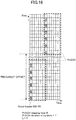
- Fig. 16 is a diagram illustrating Example (13) of frequency hopping in the embodiment of the present invention.
- Fig. 16 illustrates the arrangement of DM-RS where the PUSCH mapping type used is "PUSCH mapping type B" as illustrated in Table 2, the length of PUSCH is scheduled for 14 symbols, the "duration in symbols" of both "first hop” and “second hop” is “7", “first hop” is “I 0 ", and “second hop” is “0".
- the PUSCH start symbol is scheduled on symbol #0
- the drawing illustrates the arrangement of DM-RS with respect to a single slot.
- a data signal within PUSCH is arranged on physical resources where no DM-RS is not arranged.
- front-loaded DM-RS corresponding to first PUSCH as first hop is arranged on symbol #0.
- Front-loaded DM-RS corresponding to second PUSCH as second hop is arranged on symbol #7.
- the arrangement of DM-RS starts from a subcarrier to which frequency offset is applied as a result of the application of frequency hopping.
- Table 3 illustrates the positions of DM-RS corresponding to first hop and second hop when frequency hopping is applied to PUSCH to be transmitted in a state after the establishment of an RRC connection and one additional DM-RS is configured by higher layer signaling. Configuring one additional DM-RS by higher layer signaling may be indicated by the information element "dmrs-AdditionalPosition" that is set to "1.”
- the position of DM-RS for first hop may be "I 0 ", and the position of DM-RS for second hop may be "0".
- Fig. 17 is an exemplary modification in the embodiment of the present invention.
- the user equipment 200 applies frequency hopping to PUSCH when the PUSCH is transmitted in the state where it is not scheduled with PDCCH involving CRC not scrambled with C-RNTI or CS-RNTI, that is, in the state prior to the establishment of RRC connection, and "frequency hopping field" included in the detected PDCCH DCI format corresponding to the PUSCH to be transmitted.
- the user equipment 200 interprets that the information element "dmrs-AdditionalPosition" is "1", and one additional DM-RS is transmitted.
- the user equipment 200 interprets that the information element "dmrs-AdditionalPosition" is "0", and no additional DM-RS is transmitted.
- the user equipment 200 interprets that the information element "dmrs-AdditionalPosition" is "1", and one additional DM-RS is transmitted.
- the user equipment 200 interprets that the information element "dmrs-AdditionalPosition" is "0", and no additional DM-RS is transmitted.
- the base station apparatus 100 and the user equipment 200 can determine the number and positions of DM-RS to which frequency hopping is applied when frequency hopping is applied to PUSCH to be transmitted prior to establishment of RRC connection.
- the user equipment 200 can transmit to the base station apparatus 100 PUSCH and DM-RS to which frequency hopping is applied.
- frequency hopping is applied appropriately to a demodulation reference signal to obtain a frequency hopping gain.
- the base station apparatus 100 and the user equipment 200 include the functions for implementing the above-described examples. However, the base station apparatus 100 and the user equipment 200 each may have only a part of the functions described in the examples.
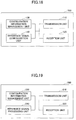
- Fig. 18 is a diagram illustrating an example of a functional configuration of the base station apparatus 100.
- the base station apparatus 100 has a transmission unit 110, a reception unit 120, a configuration information management unit 130, and a reference signal configuration unit 140.
- the functional configuration illustrated in Fig. 18 is merely an example. Any functional division or any name may be used as long as the operations according to the embodiment of the present invention can be performed.
- the transmission unit 110 includes a function of generating a signal to be sent to the user equipment 200 and sending the signal wirelessly.
- the reception unit 120 includes a function of receiving a variety of signals sent from the user equipment 200 including NR-PUSCH and obtaining from the received signals, for example, information on upper layers. Further, the reception unit 120 demodulates NR-PUSCH to which frequency hopping is applied based on DM-RS received from the user equipment 200 and to which frequency hopping has been applied. Further, the transmission unit 110 has a function of sending to the user equipment 200 NR-PSS, NR-SSS, NR-PBCH, NR-PDCCH, NR-PDSCH or the like. Further, the transmission unit 110 transmits to the user equipment 200 a variety of reference signals, for example, DM-RS.
- the configuration information management unit 130 stores preset configuration information and various types of configuration information to be sent to the user equipment 200.
- the contents of the configuration information include, for example, information on arrangement of references signal on a radio frame.
- the reference signal configuration unit 140 sets on a radio frame a variety of reference signals to be sent to the user equipment 200 from the base station apparatus 100, such as DM-RS.
- Fig. 19 is a diagram illustrating an exemplary functional configuration of the user equipment 200.
- the user equipment 200 has a transmission unit 210, a reception unit 220, a configuration information management unit 230 and a reference signal processing unit 240.
- the functional configuration illustrated in Fig. 19 is merely an example. Any functional division or any name may be used as long as the operations according to the embodiment of the present invention can be performed.
- the transmission unit 210 creates a transmission signal from transmission data and sends the transmission signal wirelessly. Further, the transmission unit 210 sends to the base station apparatus 100 a variety of reference signals such as DM-RS and NR-PUSCH corresponding to the DM-RS.
- the reception unit 220 receives a variety of signals wirelessly and obtains signals of upper layers from the received physical layer signal. Further, the reception unit 220 has a function of receiving NR-PSS, NR-SSS, NR-PBCH, NR-PDCCH, NR-PDSCH or the like sent from the base station apparatus 100.
- the transmission unit 210 sends an uplink signal to the base station apparatus 100 and the reception unit 220 receives from the base station apparatus 100 a variety of reference signals such as DM-RS, PTRS or the like.
- the configuration information management unit 230 stores various types of configuration information received from the base station apparatus 100 through the reception unit 220. Further, the configuration information management unit 230 stores preset configuration information. The contents of the configuration information include information on arrangement of reference signals on a radio frame, for example.
- the reference signal processing unit 240 performs operations of the user equipment 200 associated with reception of a reference signal to use it for channel estimation and demodulation. Further, the reference signal processing unit 240 arranges on a radio frame DM-RS to which frequency hopping is applied for demodulating NR-PUSCH to which frequency hopping is applied. A functional part of the reference signal processing unit 240 associated with reference signal transmission may be included in the transmission unit 210, and a functional part of the reference signal processing unit 240 associated with reference signal reception may be included in the reception unit 220.
- each functional block is implemented by one device which is physically and/or logically combined or may be implemented by a plurality of devices, that is, two or more devices which are physically and/or logically separated and are directly and/or indirectly connected (for example, a wired and/or wireless manner).
- each of the base station apparatus 100 and the user equipment 200 in the embodiment of the present invention may function as a computer that performs the process according to the embodiment of the present invention.
- Fig. 20 is a diagram illustrating an example of a hardware configuration of a communication device as the base station apparatus 100 or the user equipment 200 according to one embodiment of the present invention.
- Each of the base station apparatus 100 and the user equipment 200 described above may be physically configured as a computer device that includes a processor 1001, a memory 1002, a storage 1003, a communication device 1004, an input device 1005, an output device 1006, a bus 1007, and the like.
- each of the base station apparatus 100 and the user equipment 200 may be configured to include one or more devices denoted by 1001 to 1006 illustrated in the drawing or may be configured without including some devices.
- Each function in each of the base station apparatus 100 and the user equipment 200 is implemented such that predetermined software (program) is read on hardware such as the processor 1001 and the memory 1002, and the processor 1001 performs an operation and controls communication by the communication device 1004 and reading and/or writing of data in the memory 1002 and the storage 1003.
- predetermined software program
- the processor 1001 performs an operation and controls communication by the communication device 1004 and reading and/or writing of data in the memory 1002 and the storage 1003.
- the processor 1001 operates an operating system and controls the entire computer.
- the processor 1001 may be configured with a central processing unit (CPU) including an interface with a peripheral device, a control device, an operation device, a register, and the like.
- CPU central processing unit
- the processor 1001 reads a program (a program code), a software module, and data from the storage 1003 and/or the communication device 1004 out to the memory 1002, and performs various kinds of processes according to them.
- a program causing a computer to execute at least some of the operations described in the above embodiment is used as the program.
- the transmission unit 110, the reception unit 120, the configuration information management unit 130, and the reference signal configuration unit 140 of the base station apparatus 100 illustrated in Fig. 18 for example, may be implemented by a control program which is stored in the memory 1002 and operates on the processor 1001.
- 19 may be implemented by a control program which is stored in the memory 1002 and operates on the processor 1001.
- Various types of processes are described as being performed by one processor 1001 but may be performed simultaneously or sequentially by two or more processors 1001.
- the processor 1001 may be implemented by one or more chips.
- the program may be transmitted from a network via an electric communication line.
- the memory 1002 is a computer readable recording medium and configured with at least one of a read only memory (ROM), an erasable programmable ROM (EPROM), an electrically erasable programmable ROM (EEPROM), a random access memory (RAM), etc.
- ROM read only memory
- EPROM erasable programmable ROM
- EEPROM electrically erasable programmable ROM
- RAM random access memory
- the memory 1002 is also referred to as a "register,” a "cache,” a “main memory,” or the like.
- the memory 1002 can store programs (program codes), software modules, or the like which are executable for carrying out the process according to an embodiment of the present embodiment.
- the storage 1003 is a computer-readable recording medium and may be configured with, for example, at least one of an optical disk such as a compact disc ROM (CD-ROM), a hard disk drive, a flexible disk, a magneto-optical disk (for example, a compact disk, a digital versatile disk, or a Blu-ray (registered trademark) disc, a smart card, a flash memory (for example, a card, a stick, or a key drive), a floppy (registered trademark) disk, a magnetic strip, and the like.
- the storage 1003 is also referred to as an "auxiliary storage device.”
- the storage medium may be, for example, a database, a server, or any other appropriate medium including the memory 1002 and/or the storage 1003.
- the communication device 1004 is hardware (a transmitting and receiving device) for performing communication between computers via a wired and/or wireless network and is also referred to as a network device, a network controller, a network card, a communication module, or the like.
- the transmission unit 110 and the reception unit 120 of the base station apparatus 100 may be implemented by the communication device 1004.
- the transmission unit 210 and the reception unit 220 of the user equipment 200 may be implemented by the communication device 1004.
- the input device 1005 is an input device that receives an input from the outside (such as a keyboard, a mouse, a microphone, a switch, a button, a sensor, or the like).
- the output device 1006 is an output device that performs an output to the outside (for example, a display, a speaker, an LED lamp, or the like).
- the input device 1005 and the output device 1006 may be integrated (for example, a touch panel).
- the devices such as the processor 1001 and the memory 1002, may be connected via the bus 1007 to communicate information with each other.
- the bus 1007 may be configured with a single bus or may be configured with different buses between the devices.
- each of the base station apparatus 100 and the user equipment 200 may be configured to include hardware such as a microprocessor, a digital signal processor (DSP), an application specific integrated circuit (ASIC), a programmable logic device (PLD), or a field programmable gate array (FPGA) or all or some of the functional blocks may be implemented by hardware.
- the processor 1001 may be implemented by at least one of these hardware components.
- a user equipment that communicates with a base station apparatus, comprising: a processing unit, wherein when transmitting a physical uplink shared channel (PUSCH) to the base station apparatus prior to establishment of a radio resource control (RRC) connection between the base station apparatus and the user equipment, the processing unit controls frequency hopping to be applied to the PUSCH and a demodulation reference signal; a reception unit for receiving from the base station apparatus information indicating that frequency hopping is to be applied to the PUSCH; and a transmission unit for transmitting the PUSCH and the demodulation reference signal to which frequency hopping has been applied; wherein the demodulation reference signal for demodulating a single PUSCH is formed of one front-loaded demodulation reference signal and one additional demodulation reference signal, and when the duration in symbols of the PUSCH does not support one additional demodulation reference signal, the demodulation reference signal is formed of a front-loaded demodulation reference signal.
- PUSCH physical uplink shared channel
- RRC radio resource control
- the base station apparatus 100 and the user equipment 200 can determine the number of DM-RS to which frequency hopping is applied.
- the user equipment 200 can transmit to the base station apparatus 100 the PUSCH and DM-RS to which frequency hopping has been applied. That is, frequency hopping can be applied to a demodulation reference signal appropriately in a wireless communication system to obtain a frequency hopping gain.
- the processing unit may determine, on the basis of the duration in symbols of the PUSCH, the position of a symbol in the time domain on which a frequency-hopped demodulation reference signal is arranged.
- the base station apparatus 100 and the user equipment 200 can determine, on the basis of the duration in symbols of the PUSCH, the position of a symbol in the time domain on which frequency-hopped DM-RS is arranged.
- the information indicating that frequency hopping is to be applied may be a frequency hopping field included in a downlink control information (DCI) format of a detected physical downlink control channel (PDCCH) corresponding to the transmitted PUSCH.
- DCI downlink control information
- PDCCH physical downlink control channel
- the demodulation reference signal may include one additional reference signal, and when the duration in symbols of the PUSCH is less than 7, the demodulation reference signal may include no additional demodulation reference signal.
- the base station apparatus 100 and the user equipment 200 can determine, on the basis of the duration in symbols of the PUSCH, the number of DM-RS to be arranged.
- the demodulation reference signal may include one additional reference signal, and when the duration in symbols of the PUSCH is less than 5, the demodulation reference signal may include no additional demodulation reference signal.
- the base station apparatus 100 and the user equipment 200 can determine, on the basis of the duration in symbols of the PUSCH, the number of DM-RS to be arranged.
- a base station apparatus that communicates with a user equipment, comprising: a configuration unit, wherein when the base station apparatus receives a physical uplink shared channel (PUSCH) prior to establishment of a radio resource control (RRC) connection between the user equipment and the base station apparatus, the configuration unit configures frequency hopping to be applied to the PUSCH and a demodulation reference signal; a transmission unit for transmitting to the user equipment information indicating that frequency hopping is to be applied to the PUSCH; and a reception unit for receiving the PUSCH and the demodulation reference signal to which frequency hopping has been applied; wherein the demodulation reference signal for demodulating a single PUSCH is formed of one front-loaded demodulation reference signal and one additional demodulation reference signal, and when the duration in symbols of the PUSCH does not support one additional demodulation reference signal, the demodulation reference signal is formed of a front-loaded demodulation reference signal.
- PUSCH physical uplink shared channel
- RRC radio resource control
- the base station apparatus 100 and the user equipment 200 can determine the number of DM-RS to which frequency hopping is applied.
- the user equipment 200 can transmit to the base station apparatus 100 the PUSCH and DM-RS to which frequency hopping has been applied. That is, frequency hopping can be applied to a demodulation reference signal appropriately in a wireless communication system to obtain a frequency hopping gain.
- the operations of two or more functional units may be performed by a single physical component or the operation of a single functional unit may be performed by two or more physical components.
- the order of steps of the process procedure described in the present embodiment may be interchanged unless incompatible.
- the functional block diagrams have been used to describe the base station apparatus 100 and the user equipment 200. However, such devices may be implemented by hardware, software or a combination of hardware and software.
- Software operated by a processor included in the base station apparatus 100 according to the embodiment of the present invention and software operated by a processor included in the user equipment 200 according to the embodiment of the present invention may be stored in random access memory (RAM), flash memory, read only memory (ROM), EPROM, EEPROM, a register, hard disk drive (HDD), a removable disk, CD-ROM, database, server, or any other appropriate storage medium.
- RAM random access memory
- ROM read only memory
- EPROM EPROM
- EEPROM electrically erasable programmable read only memory
- register read only memory
- HDD hard disk drive
- CD-ROM compact disc-read only memory
- database database
- server or any other appropriate storage medium.
- Notification of information is not limited to the aspects/embodiments described in this specification, but may be performed using other methods.
- the notification of information may be performed physical layer signaling (such as downlink control information (DCI) or uplink control information (UCI)), higher layer signaling (such as radio resource control (RRC) signal, medium access control (MAC) signaling, or broadcast information (master information block (MIB) and system information block (SIB))), other signals, or combinations thereof.
- the RRC signaling may be referred to as an RRC message and may be, for example, an RRC connection setup message or an RRC connection reconfiguration message.
- LTE long term evolution
- LTE-A LTE-advanced
- SUPER 3G IMT-Advanced
- 4G 5G
- future radio access FAA
- W-CDMA registered trademark
- GSM registered trademark
- CDMA2000 ultra mobile broadband
- UMB ultra mobile broadband
- IEEE 802.11 Wi-Fi
- IEEE 802.16 WiMAX
- IEEE 802.20 ultra-wideband
- UWB ultra-wideband
- Bluetooth registered trademark
- processing sequences, the sequences, the flowcharts and the like of the embodiment/examples described above in this specification may be changed in the order as long as they are not incompatible with each other.
- various steps as elements are described in an exemplary order and the method is not limited to the described order.
- the certain operations described in the specification as being performed by the base station apparatus 100 may be performed by an upper node in some cases.
- a network formed by one or more network nodes having the base station apparatus 100 it is clear that various operations performed for connection with the user equipment 200 could be performed by the base station apparatus 100 and/or a network node other than the base station apparatus 100 (e.g., may be, but is not limited to MME or S-GW).
- a network node other than the base station apparatus 100 e.g., may be, but is not limited to MME or S-GW.
- a combination of a plurality other network nodes e.g., MME and S-GW
- the user equipment 200 may also be referred to as a subscriber station, a mobile unit, a subscriber unit, a wireless unit, a remote unit, a mobile device, a wireless device, a wireless communication device, a remote device, a mobile subscriber station, an access terminal, a mobile terminal, a wireless terminal, a remote terminal, a handset, a user agent, a mobile client, a client, or several appropriate terms by those skilled in the art.
- the base station apparatus 100 may be referred to as a NodeB (NB), evolved NodeB (eNB), next generation NodeB (NE nodeB (gNB)), a base station or some other appropriate terms by those skilled in the art.
- NB NodeB
- eNB evolved NodeB
- NE nodeB next generation NodeB
- a base station or some other appropriate terms by those skilled in the art.
- determining (determining) and “deciding (determining)” used in this specification may include various types of operations. For example, “determining” and “deciding” may include deeming that to perform judging, calculating, computing, processing, deriving, investigating, looking up (e.g., search in a table, a database, or another data structure), or ascertaining is to perform “determining” or “deciding”. Furthermore, “determining” and “deciding” may include deeming that to perform receiving (e.g., reception of information), transmitting (e.g., transmission of information), input, output, or accessing (e.g., accessing data in memory) is to perform "determining” or "deciding”.
- receiving e.g., reception of information
- transmitting e.g., transmission of information
- input, output, or accessing e.g., accessing data in memory
- determining and “deciding” may include deeming that to perform resolving, selecting, choosing, establishing, or comparing is to perform “determining” or “deciding". Namely, "determining” and “deciding” may include deeming that some operation is to perform "determining” or "deciding".
- DM-RS is an example of reference signals.
- Front-loaded DM-RS is one example of front-loaded demodulation reference signals.
- Additional DM-RS is an example of additional demodulation reference signals.
- the reference signal processing unit 240 is an example of processing units.
- the reference signal configuration unit 140 is an example of configuration units.
Landscapes
- Engineering & Computer Science (AREA)
- Signal Processing (AREA)
- Computer Networks & Wireless Communication (AREA)
- Mobile Radio Communication Systems (AREA)
Applications Claiming Priority (1)
| Application Number | Priority Date | Filing Date | Title |
|---|---|---|---|
| PCT/JP2018/013988 WO2019187157A1 (ja) | 2018-03-30 | 2018-03-30 | ユーザ装置及び基地局装置 |
Publications (2)
| Publication Number | Publication Date |
|---|---|
| EP3780530A1 true EP3780530A1 (de) | 2021-02-17 |
| EP3780530A4 EP3780530A4 (de) | 2021-12-01 |
Family
ID=68058113
Family Applications (1)
| Application Number | Title | Priority Date | Filing Date |
|---|---|---|---|
| EP18911793.0A Pending EP3780530A4 (de) | 2018-03-30 | 2018-03-30 | Benutzergerät und basisstationsvorrichtung |
Country Status (5)
| Country | Link |
|---|---|
| US (1) | US11575477B2 (de) |
| EP (1) | EP3780530A4 (de) |
| JP (1) | JP7353269B2 (de) |
| CN (1) | CN111971940B (de) |
| WO (1) | WO2019187157A1 (de) |
Families Citing this family (1)
| Publication number | Priority date | Publication date | Assignee | Title |
|---|---|---|---|---|
| CN114698112A (zh) * | 2020-12-30 | 2022-07-01 | 展讯通信(上海)有限公司 | 一种信息处理的方法及通信装置 |
Family Cites Families (19)
| Publication number | Priority date | Publication date | Assignee | Title |
|---|---|---|---|---|
| RU2009134937A (ru) * | 2007-03-01 | 2011-04-10 | НТТ ДоСоМо, Инк. (JP) | Базовая станция и способ управления связью |
| CN104254995B (zh) * | 2012-01-24 | 2018-05-11 | 交互数字专利控股公司 | 用于改善的上行链路覆盖的系统和方法 |
| CN104685948A (zh) * | 2012-09-27 | 2015-06-03 | 夏普株式会社 | 终端、通信方法以及集成电路 |
| US11202183B2 (en) * | 2015-06-25 | 2021-12-14 | Qualcomm Incorporated | Retuning for enhanced machine type communication |
| CN111148246B (zh) * | 2017-02-03 | 2021-02-23 | Oppo广东移动通信有限公司 | 信息传输方法、装置和存储介质 |
| KR20240159031A (ko) * | 2017-02-03 | 2024-11-05 | 주식회사 윌러스표준기술연구소 | 무선 통신 시스템에서 레퍼런스 신호 및 데이터 채널의 송수신 방법, 장치, 및 시스템 |
| JP6974430B2 (ja) * | 2017-03-21 | 2021-12-01 | エルジー エレクトロニクス インコーポレイティドLg Electronics Inc. | 無線通信システムにおける端末と基地局の間の物理上りリンク制御チャネルの送受信方法及びそれをサポートする装置 |
| CN108632005B (zh) * | 2017-03-24 | 2023-12-15 | 华为技术有限公司 | 一种参考信号传输方法、装置及系统 |
| EP3619882B1 (de) * | 2017-05-04 | 2022-11-23 | Apple Inc. | Datenstrukturen und übetragungsschemata für die aufwärtsstrecke der übertragung in nr-kommunikationssystemen |
| CN110999185B (zh) * | 2017-06-09 | 2022-08-05 | Lg电子株式会社 | 在无线通信系统中发送/接收参考信号的方法及其装置 |
| US11418379B2 (en) * | 2017-06-09 | 2022-08-16 | Lg Electronics Inc. | Method for transmitting/receiving reference signal in wireless communication system, and device therefor |
| EP4459937A3 (de) * | 2017-06-13 | 2025-01-22 | Apple Inc. | Verbesserung bei planung und harq-ack-rückkopplung für urllc, multiplexing-schema für steuer/datenkanal und dm-rs |
| CN111108730B (zh) * | 2017-06-21 | 2023-09-19 | 苹果公司 | 同步信号(ss)块的冲突处理 |
| WO2019032741A1 (en) * | 2017-08-10 | 2019-02-14 | Sharp Laboratories Of America, Inc. | LONG UPLINK CONTROL (LONG PUCCH) PHYSICAL CHANNEL DESIGN INTERVAL STRUCTURE FOR A NEW 5TH GENERATION (5G) RADIO (NR) |
| US11212053B2 (en) * | 2017-08-11 | 2021-12-28 | Qualcomm Incorporated | Methods and apparatus related to demodulation reference signal design and related signaling |
| JP7049452B2 (ja) * | 2017-11-13 | 2022-04-06 | エルジー エレクトロニクス インコーポレイティド | 無線通信システムにおいてデータを送受信するための方法及びそのための装置 |
| US11121825B2 (en) * | 2017-11-26 | 2021-09-14 | Qualcomm Incorporated | Mapping uplink control information to uplink data channel in wireless communication |
| US10897755B2 (en) * | 2017-12-22 | 2021-01-19 | Samsung Electronics Co., Ltd | Method and apparatus for configuring demodulation reference signal information in wireless cellular communication system |
| JP2020521365A (ja) * | 2018-02-14 | 2020-07-16 | エルジー エレクトロニクス インコーポレイティド | 非免許帯域を支援する無線通信システムにおいて端末と基地局の間の上りリンク信号を送受信する方法及びそれを支援する装置 |
-
2018
- 2018-03-30 JP JP2020508921A patent/JP7353269B2/ja active Active
- 2018-03-30 US US16/982,259 patent/US11575477B2/en active Active
- 2018-03-30 WO PCT/JP2018/013988 patent/WO2019187157A1/ja not_active Ceased
- 2018-03-30 CN CN201880091685.1A patent/CN111971940B/zh active Active
- 2018-03-30 EP EP18911793.0A patent/EP3780530A4/de active Pending
Also Published As
| Publication number | Publication date |
|---|---|
| CN111971940B (zh) | 2023-07-18 |
| US11575477B2 (en) | 2023-02-07 |
| EP3780530A4 (de) | 2021-12-01 |
| US20210058203A1 (en) | 2021-02-25 |
| JP7353269B2 (ja) | 2023-09-29 |
| JPWO2019187157A1 (ja) | 2021-02-25 |
| CN111971940A (zh) | 2020-11-20 |
| WO2019187157A1 (ja) | 2019-10-03 |
Similar Documents
| Publication | Publication Date | Title |
|---|---|---|
| US10993174B2 (en) | User apparatus, base station, and preamble transmission method | |
| US11128514B2 (en) | Terminal and base station apparatus for arranging and receiving a phase tracking reference signal | |
| US11129203B2 (en) | User apparatus, and random access preamble transmission method | |
| US12150144B2 (en) | Terminal, base station apparatus, communication method, and apparatus | |
| WO2018203417A1 (ja) | 基地局装置、ユーザ装置及び通信方法 | |
| JPWO2018229964A1 (ja) | 基地局装置 | |
| JP7079273B2 (ja) | 端末、通信方法及び基地局 | |
| US11419144B2 (en) | User apparatus and base station apparatus | |
| US11575477B2 (en) | User equipment and base station apparatus | |
| US11799603B2 (en) | Base station apparatus | |
| CN113455068A (zh) | 用户装置以及基站装置 | |
| US20230300650A1 (en) | Terminal and measurement method | |
| US11445554B2 (en) | User equipment and base station apparatus | |
| CA3092291C (en) | User equipment and base station apparatus | |
| US20220361248A1 (en) | Terminal and transmission method | |
| JP7245891B2 (ja) | 基地局及び通信方法 | |
| OA19693A (en) | Base station apparatus and user equipment. |
Legal Events
| Date | Code | Title | Description |
|---|---|---|---|
| STAA | Information on the status of an ep patent application or granted ep patent |
Free format text: STATUS: THE INTERNATIONAL PUBLICATION HAS BEEN MADE |
|
| PUAI | Public reference made under article 153(3) epc to a published international application that has entered the european phase |
Free format text: ORIGINAL CODE: 0009012 |
|
| STAA | Information on the status of an ep patent application or granted ep patent |
Free format text: STATUS: REQUEST FOR EXAMINATION WAS MADE |
|
| 17P | Request for examination filed |
Effective date: 20201001 |
|
| AK | Designated contracting states |
Kind code of ref document: A1 Designated state(s): AL AT BE BG CH CY CZ DE DK EE ES FI FR GB GR HR HU IE IS IT LI LT LU LV MC MK MT NL NO PL PT RO RS SE SI SK SM TR |
|
| AX | Request for extension of the european patent |
Extension state: BA ME |
|
| RAP3 | Party data changed (applicant data changed or rights of an application transferred) |
Owner name: NTT DOCOMO, INC. |
|
| DAV | Request for validation of the european patent (deleted) | ||
| DAX | Request for extension of the european patent (deleted) | ||
| A4 | Supplementary search report drawn up and despatched |
Effective date: 20211029 |
|
| RIC1 | Information provided on ipc code assigned before grant |
Ipc: H04W 72/04 20090101ALI20211025BHEP Ipc: H04L 27/26 20060101AFI20211025BHEP |
|
| P01 | Opt-out of the competence of the unified patent court (upc) registered |
Effective date: 20230509 |
|
| STAA | Information on the status of an ep patent application or granted ep patent |
Free format text: STATUS: EXAMINATION IS IN PROGRESS |
|
| 17Q | First examination report despatched |
Effective date: 20250814 |